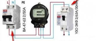
In modern housing, great importance is attached to protecting the electrical network from severe overvoltages. For this purpose, network stabilizers are used, which smooth out sharp fluctuations, but have a number of disadvantages. It is much more profitable to use inexpensive and compact 220V voltage relays for the home, which provide reliable protection for household networks. These devices, abbreviated as RKN, are mounted in the distribution panel and do not require significant space within the apartment.
Operating principle and functionality
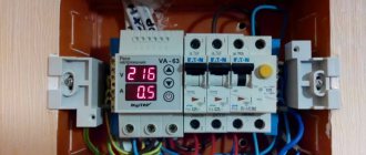
Multifunctional relay DigiTOP VA-32A
The operating principle of the device, known to most amateurs under the name 220V voltage limiter, can be understood after familiarizing yourself with its device. The composition includes the following units:
- electronic control module, adjustable for lower and upper limits;
- control signal generator;
- an electromagnetic relay that turns off the device when the set point is exceeded.
When the network voltage reaches one of the maximum levels, the electronics generates a control signal that supplies power to the control relay. It is triggered and de-energizes the line, protecting household appliances connected to the sockets.
Relay operating principle
The functionality of such products in comparison with the same stabilizer is significantly expanded:
- You can set two response thresholds (upper and lower).
- The devices have LED indicators built into the front panel and provide monitoring of the presence of voltage at the input and output.
- There is a liquid crystal display on which the values of the main mains power parameters are recorded.
The listed possibilities significantly facilitate the operation of protective equipment installed in an apartment or in a country house.
Why do you need a voltage regulating relay?
The proper name for the device in question is “voltage control relay.” But the middle word in conversations between electricians often falls out of this term.
In principle, this is one and the same electrical safety device. Plus, this equipment is often called “zero break protection”. Why will become clear below.
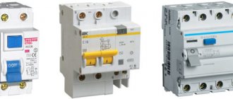
Do not confuse RCD and RKN automatic devices. The former protect the line from overload and short circuit, and the latter from power surges. These are devices with different functional purposes.
The main task of the RKN is to disconnect electrical appliances from the network when the voltages in it are too high or too low, so that the equipment connected to the power supply does not fail
The inscription “~220 V” is familiar to all Russians. Household appliances connected to sockets operate at this alternating voltage in the house. However, in fact, the maximum voltage in the home electrical network only fluctuates around this mark with a spread of +/-10%.
In some cases, the differences reach large values. The voltmeter may well show drops of up to 70 and surges of up to 380 W.
For electrical engineering, both excessively low and high voltages are dangerous. If the refrigerator compressor does not receive enough electricity, it simply will not start. As a result, the equipment will inevitably overheat and break down.
At low voltage, the average person in most cases is not even able to outwardly determine whether the equipment is working properly or not in such a situation. Visually, you can only see dimly glowing incandescent light bulbs, the voltage to which is supplied less than it should be.
With high bursts everything is much simpler. If you apply 300-350 W to the power input of a TV, computer or microwave, then at best the fuse in them will blow. And most often they will “burn out” themselves. And it’s also good if there is no real ignition of the equipment and no fire.
Apartment buildings are usually powered from a three-phase 380 V network, and the apartment already has single-phase 220 V wiring from the electrical panel on the floor
The main problems with voltage drops in high-rise buildings arise due to a break in the working zero. This wire is damaged due to carelessness by electricians during repairs, or it itself simply burns out from old age.
If the house on the access line has a set of the necessary protection of a modern level, then as a result of such a break, the automatic RCD is triggered. Everything ends relatively normally.
However, in old housing stock, where there are no circuit breakers, the loss of zero leads to phase imbalance. And then in some apartments the voltage becomes low (50–100 V), and in others it becomes sharply high (300–350 V).
Who will end up with what comes out of the outlet depends on the load connected to the power grid at that particular moment. It is impossible to accurately calculate and predict this in advance.
As a result, for some, all equipment stops working, while for others it burns out from overvoltage. This is where you need a voltage control relay. If problems arise, it will turn off the network, preventing damage to TVs, refrigerators, etc.
In the private sector, the problem with voltage surges is somewhat different. If the cottage is located at a great distance from the street transformer, then with increased electricity consumption in houses before it, at this extreme point the voltage may drop to critically low levels.
As a result, due to a prolonged lack of “volts”, electric motors in household electrical appliances will inevitably begin to burn and fail.
Classification and types
Extension cord with voltage relay
Known types of RKN differ in the type of power used in the home, according to which they are single-phase or three-phase. 220V supply voltage relays are installed in urban housing, and their three-phase analogues are used in offices or enterprises. They are often found in private houses, to which a branch from the 380 Volt line (three-phase power) is connected.
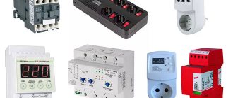
According to the method of connection to the serviced line, well-known models of 220V mains voltage control relays for the home are divided into the following types:
- adapters that plug into a regular outlet;
- extension cords with several sockets (from 1 to 6);
- devices mounted in a panel on a DIN rail.
The first two positions are transition devices that provide protection for individual household consumers. This is how they fundamentally differ from RLVs installed in a distribution cabinet. Entire groups of electrical appliances can be connected to them.
Advantages and disadvantages of products plugged into an outlet
Voltage relay with plug and socket
Before purchasing a voltage control relay for a socket, it is important to evaluate its advantages that justify the purchase.
- Easy to install, compact and portable (can be used anywhere);
- relatively low cost;
- attractive design that does not interfere with the interior of the premises;
- versatility: permissibility of use to protect an individual consumer or several loads at once.
The design of adapters and extensions is well designed. Their appearance satisfies the most demanding needs and does not introduce visible disturbances into the interiors of the rooms. Disadvantages include the lack of a number of options available for devices mounted on a DIN rail.
Summarize
Given the state of electrical networks and transformers at substations, especially in private sectors, the purchase of a voltage control relay and its installation is already becoming a necessity. And for those who think the cost of such protective devices is too high, the Homius.ru editors have prepared advice: calculate how much it might cost to repair all the household appliances in your apartment or private house. After making some simple calculations, you are guaranteed to change your decision. The main thing here is to take the time, namely, before purchasing, familiarize yourself not only with the range of products offered by the manufacturer, but also with real reviews from users who have installed such protection. This is the only way to understand whether it is worth purchasing this or that model.
Table of maximum permissible deviations of voltage indicators, according to GOST
We hope that the information presented in today's article was useful to our dear reader. If you have any questions while reading it, feel free to ask them in the discussions below. The Homius.ru editors will be happy to answer them as quickly as possible. If you have installed such protective equipment, please share your impressions with less experienced home craftsmen planning a similar installation. Write, share, ask. And finally, according to the established good tradition, we bring to your attention one interesting video on today’s topic, from which you will learn a lot of new things.
Watch this video on YouTube
Previous Engineering Electric heat gun 220 V: high-quality heating of residential premises, garages, warehouses Next Engineering Alternative energy sources: saving time
Which type is preferable?
Single-phase voltage relay RN-111M 1F NOVATEK
If the user is concerned about the safety of an expensive model of a refrigerator, for example, and all other devices are already protected by a stabilizer, it is more convenient to purchase a sample of the “socket-plug” type.
In this case, installing a general automatic device will be unnecessary, as it will lead to unjustified costs. This option is more suitable for residents of city apartments who do not want to spend money on installing an RKN in the distribution panel (for this you will have to invite an electrician).
Regardless of the operating conditions of the control relay, it should be understood that installing several devices in an outlet will cost more than one in a panel.
When there is no stabilizer in the house, and its owner wants to reliably protect kitchen and room equipment, it is wiser to choose a device mounted on a DIN rail. By installing several relays - one for each protected line - the possibility of breakdown of expensive equipment is completely eliminated. They are optimally suited for a private home, where they can also control a three-phase network.
Features of the ILV installation
Installation diagram
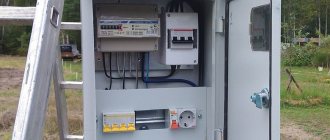
The general procedure for installing a relay in an electrical cabinet is determined by the requirements of current standards (PUE, in particular). Each specific ILV model can be installed in accordance with the functions it performs. The following options for installing a relay in the electrical wiring line are possible:
- placement immediately after the electric meter (this method is considered classic);
- connection together with an RCD and a linear machine, which expands the functionality of the device;
- installation before the electric meter, allowing you to protect the metering device itself from overvoltages.
The latter option is possible only after obtaining permission from Energosbyt representatives.
Depending on the method of connection to the load, various types of RLVs are installed either according to a direct connection to the load, or through the power contacts of a magnetic starter. The second option significantly expands the device’s load current capabilities.
Device and principle of operation
The relay is equipped with a housing made of special plastic; inside there is a measuring block and a contact group. The measurement module measures the voltage in the circuit, the resulting result is compared with a pre-programmed interval. If the numbers match, then the contacts of the executive unit are in a closed state, maintaining the functionality of the external circuit. The contact group does not require a continuous supply of electricity to hold the plates in closed or open states; current is supplied only at the moment of switching.
The meter constantly monitors the voltage; if the parameter deviates from the programmed interval, a control signal is generated. The pulse is transmitted to the contact group, which cuts off power from the equipment in the apartment or residential building. The design of the equipment provides for non-volatile memory in which information about the last emergency operation is stored. Voltage control is carried out by a microprocessor or a comparing device (comparator).
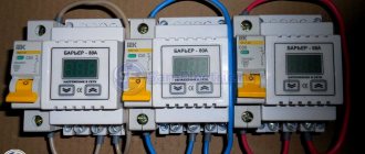
There are simplified relays from which the liquid crystal display has been removed. To change parameters, handles equipped with a measuring scale are used. The circuit provides signal LEDs that allow you to determine the reason for the contact group to operate. The electronic controller and mechanical relay part remain unchanged.
Voltage relay functions.
All protective relays are designed with an adjustable power-on delay timer. The device is necessary for the correct connection of equipment equipped with electric motors. For example, it is recommended to connect the refrigerator compressor to the network 1-2 minutes after an emergency shutdown. Depending on the manufacturer, timers are used that are designed to set a delay for a period of time from 15 seconds to 15 minutes.
Setting modes
Relay settings buttons
Threshold values of the RKN are set using several potentiometers on a graduated scale placed together with knobs on the front panel.
In some samples, buttons are used to set response limits.
The step with which the lower and upper limits are set for most RKN samples is one Volt. The correct setting of the required parameter is controlled by the indicator board located on the front panel of the device.
On some models, there is another regulator that sets the time for the device to return to its original state, the moment when the load is reconnected to the power circuit. It can be set in a wide range of values from several seconds to 10 minutes.
Description of popular models
The connection diagrams and settings of most models offered by domestic manufacturers have much in common; they may differ only in details.
Devices under the Zubr brand
Protective devices of this series are activated in the power supply circuit in two ways:
- simplified internal connection;
- together with RCD and circuit breaker.
In the first case, the load is connected directly to the output of the device, and in the second, the control circuit is closed through an RCD and an AV. This inclusion of the Bison allows you to protect the line not only from voltage surges, but also from current leaks.
The devices have various designs, differing in rated currents (25-63 Amperes). The upper response threshold is from 220 to 280 in steps of 1 Volt, and its lower value is from 120 to 210 Volts. The time to reconnect to the line varies from 3 to 600 seconds. The adjustment step is 3 seconds.
RN series
RN-111
Model RN-113 is switched on after the electric meter and allows manual setting of the values of the lower and upper response thresholds, indicated on the display built into the front panel. The device is capable of automatically connecting the power supply when its parameters are restored after strong power surges.
For normal operation of devices in this series, a power reserve of at least 20% is required.
In addition to the limit values, the indicator displays the network parameters when the consumer is disconnected, as well as the time remaining before switching on. Rated current is 32 Amps; if desired, it can be increased by installing a magnetic starter.
UZM series
Voltage relay UZM-51M
The UZM-51M device, installed immediately after the electric meter, is designed for a rated current of up to 63 Amperes and occupies 2 modules on a DIN rail at once. Its standard width is 35 mm. The maximum setpoint for the upper voltage limit is 290 Volts. The lower threshold for overvoltage is 100 Volts.
The restart time, manually set by the user, can take two fixed values - 10 seconds and 6 minutes. Devices of the UZM series can be installed in networks with any grounding system: TN-C, TN-S or TN-CS.
Devices from
V-protector series VLVs are used only for protection against voltage surges. They are designed for rated currents from 16 to 63 Amps. The upper threshold is set in the range from 210 to 270, and the lower – from 120 to 200 Volts. The time for automatic restoration of the on state is from 5 to 600 seconds. The three-phase V-protector 38 device is designed for a maximum current of no more than 10 Amperes.
Connection diagrams
There are two main ways to connect RKN - direct, when the workload passes through RKN contracts, and indirect - the load is switched through a contactor. The second method is needed when connecting a load above 7 kW. Recommendations for connection:
- the relay should be installed after the electricity meter;
- install a protective device (input machine) in front of the launch vehicle;
- accessibility of the device for maintenance and visual monitoring of operation.
Connecting a single-phase RKN
Single-phase RKNs are connected directly to the network, and the operating current of the network passes through their contacts. As a rule, an RCD or a circuit breaker is installed in front of the relay to protect against current leakage. The connection algorithm is as follows:
- The zero from the input machine is connected to the zero bus, and then to terminal N on the relay.
- The phase wire is directly connected to terminal L.
- The third terminal of the RKN is intended for connecting the load, the ground and zero for which are taken from the busbars.
Connecting a three-phase RKN
To directly connect a three-phase IVR you must:
- Connect the phase wires of the three-pole input circuit breaker.
- Install the RKN by connecting the phases and neutral to the corresponding terminals.
- Connect the phases and neutral to the terminals of the RCD.
- Turn on the load by connecting the ground and phases, as well as zero from the N-bus installed after the RCD.
Connection diagram for RLV for powerful consumers with contactor
When the switched currents are significantly greater than the maximum permissible value of the RKN, the device is used in conjunction with a magnetic starter (contactor). When choosing devices, you should pay attention to the speed - the lower the response speed of both devices, the better.
Advice : it is cheaper to buy a contactor and voltage relay than to choose an RKN for powerful consumers.
The circuit differs from a conventional connection in that a contactor is installed after the circuit breaker, which switches the load. The relay is connected in parallel to the starter and only controls the voltage value. In case of significant deviations, the switch is activated, de-energizing the contactor coil, which leads to disconnection of the load.
