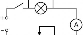
Each home has a certain set of tools with which you can solve urgent problems in repairing household appliances, electrical wiring, lighting fixtures and other objects. Among them, special mention should be made of the voltage indicator, which allows you to accurately determine the presence or absence of electricity in a particular area. This device becomes relevant in the event of a sudden loss of light, since it is the voltage indicator that is used during initial measures.
From neon to LED
The solution was to change the glow mode itself from continuous to pulsed.
If you try to estimate the power consumed by a neon lamp, then at a voltage of 100 V and a capacitive current of 20 μA, it will be 100 x 20 μA = 2 mW. If you supply such power to the LED over a time interval, for example, 10 ms, and not a whole second, then it will light up quite well during this interval. After all, at a voltage of 100 V, the current through it will be 0.002 W x 100/100 V = 0.002 A = 2 mA. If you ensure the accumulation of energy in some circuit (for example, in a relaxation generator) for a fraction of a second, and then sharply release it to the LED in 10 ms, then the latter will periodically flash brightly. You will get an LED voltage indicator without a built-in battery.
Rules for choosing a hidden wiring indicator
Models of hidden wiring indicators, for the most part, guarantee the functionality described in the instructions.
When purchasing a detector, keep the receipt, packaging and warranty card. If the device does not work, you can always exchange it for a more suitable model with an additional payment.
However, there are features of choice that the average person does not think about when purchasing specialized electrical equipment.
They are listed in the form of a list of rules:
- The physical parameters of foreign power grids may differ greatly from domestic ones, so you should not buy power supply systems that are not certified under national legislation.
- It is necessary to take into account the material of the walls in the place where the device is intended to be used and the depth of the wiring.
- When determining the locations of inactive wiring, devices with metal sensors are needed.
- After purchasing the device, it is advisable to check its performance in the store. The detection depth can be assessed by covering the cable with a ceramic tile, wooden board or sheet of foam.
- Due to their simplicity of design, budget models can be more durable than ICPs with complex electronic circuits.
When purchasing a hidden wiring detector, you should definitely consult with the seller, because if you choose on your own, there is a high probability that the purchased equipment will not fully meet the tasks assigned to it.
The following photo selection will introduce you to the detector models that are in demand on the market, allowing you to accurately determine the position of the hidden wiring route:
Working with a 220 V network
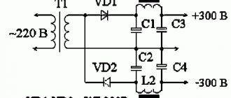
The simplest mains voltage indicator without a power source is made from a resistor, a current limiter (transistor), a rectifier (diode) and any LED. Resistor resistance is 100 - 150 kOhm.
Diode characteristics:
- current 10-100 mA;
- voltage 1-1.1 V;
- reverse voltage 30-75 V.
At 220 V, 3 Hz, the LED lights up. You can adjust the frequency and increase the brightness by changing the capacitance of the capacitor. Such an indicator operates at a minimum voltage of 4.5 V. In addition to the mains current, it can determine the serviceability, on and off state of an electrical appliance.
DC Voltage Check
To check the 12-volt network and the integrity of the connections, you can make another LED indicator (you need 2 multi-colored LED elements). To limit the current, you can use a resistor with a resistance of 50-100 Ohms or an incandescent light bulb with low power. One of the LEDs lights up when a voltage of the appropriate polarity is connected.
This device is suitable for working with alternating and constant voltage networks of 5-600 V.
Indicator for microcircuits - logic probe
Devices for indicating microcircuits are called logic probes. This indicator is three-level (3 LEDs are included in the circuit).
A logic probe allows you to:
- determine phase, short circuit, resistance of the electrical network;
- establish the presence of voltage 12 - 400 V;
- determine the poles for direct current;
- check the condition of diodes, transistors and other parts;
- determine the integrity of the electrical network by ringing;
- diagnose relay and coil breaks;
- ring chokes and motors;
- determine the terminals of transformers.
The power source is a 9 V battery. When the pins are closed, a current of 110 mA is consumed. After opening, no current is consumed; there is no need to install a switch or mode switch.
When checking a network with a resistance of 0 - 150 Ohms, 2 LEDs light up, and when the indicator increases, one LED lights up. At 220-380 volts the third one lights up, the rest flicker. If the circuit is broken, the LEDs will not light up. At zero on the contact 0.5 V, one transistor opens (KT315B), at 2.4 V - the second (KT203B).
It is possible to replace transistors with others having similar parameters.
Voltage indicator on two-color LED
Another simple indicator chip - with a two-color LED. Some home craftsmen use it to determine the operating mode of the lamp. For example, a basement light switch equipped with an indicator is mounted on a staircase. If it is on, the glow is red, after turning it off it is green.
Option for car
The circuit for indicating the battery charge and vehicle network voltage consists of:
- RGB LED;
- 3 zener diodes;
- 3 bipolar transistors (BC847C);
- 9 resistors;
The level is determined by color. Green glow at 12-14 V, blue at 11.5 V, red at 14.4 V).
If no errors were made when assembling the circuit, one of the resistors (2.2 kOhm) and the transistor (8.2 V) determine the minimum voltage limit. When the indicator decreases, the transistor corresponding to the blue glow connects the crystal.
If the voltage does not decrease or increase, the current passes through 2 resistors, a 5.6 V zener diode and an LED, a green glow appears (the transistors corresponding to red and blue turn off). When the voltage increases to 14.4 V, the red light comes on.
What is a logic probe used for?
This device is successfully used when it is necessary to perform a preliminary check of the operability of the elements of a simple electrical circuit, as well as for the initial diagnosis of simple devices - that is, in cases where high measurement accuracy is not required. Using a logic probe you can:
- Determine the presence of a voltage of 12 - 400 V in the electrical circuit.
- Determine the poles in a DC circuit.
- Check the condition of transistors, diodes and other electrical elements.
- Determine the phase conductor in the AC electrical circuit.
- Ring the electrical circuit to check its integrity.
Digital voltage indicator
The glow of a neon light bulb or LED is, of course, a reliable way to indicate the presence of voltage, but it is too uninformative if the circuit has several voltage levels. In this case, measuring electronics, which has rapidly developed in recent decades, comes to the rescue.
The simplest way to make the indicator more informative is to introduce several voltage comparators into its circuit, which operate at different voltage levels. The output of each comparator controls its own indication element on the device body.
A real digital voltage indicator is obtained if the measured voltage is digitized on the built-in ADC, and then, through a special circuit, is supplied to seven-segment display elements capable of displaying numbers from 0 to 9, or to a small-sized matrix digital indicator. Expensive professional voltage indicators are built using this scheme.
Can I get an electric shock through an indicator screwdriver?
Through a working one, no, if you do not touch the metal rod. The sensitive value for humans is 10 mA. In the device it is limited to a few microamps.
The tester is a must-have for any master. It must be in the tool box. This is a quick way to find the voltage in your household electrical network. If you know what an indicator screwdriver is and how to use it, then you can easily test the line, test the circuits for breaks or short circuits, and also check the polarity of the batteries.
Electrician's probe: principle of operation and manufacture
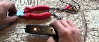
A simple identifier with two LEDs and a neon light bulb, which has received the name “arcashka” among electricians, despite its simple device, allows you to effectively determine the presence of a phase, resistance in an electrical circuit, and also detect a short circuit (short circuit) in the circuit. The universal electrician's tester is mainly used for:
- Diagnostics for broken coils and relays.
- Continuity checks of motors and chokes.
- Checking rectifier diodes.
- Definitions of terminals on transformers with multiple windings.
This is not a complete list of tasks that can be solved using a probe. But the above is enough to understand how useful this device is in the work of an electrician.
A regular battery with a voltage of 9 V is used as a power source for this device. When the tester probes are closed, the current consumption does not exceed 110 mA. If the probes are open, then the device does not consume electricity, so it does not need either a diagnostic mode switch or a power switch.
The probe is capable of performing its full functions until the voltage at the power supply drops below 4 V. After this, it can be used as a voltage indicator in circuits.
During the continuity of electrical circuits, the resistance of which is 0 - 150 Ohms, two light-emitting diodes light up - yellow and red. If the resistance value is 151 Ohm - 50 kOhm, then only the yellow diode lights up. When a network voltage of 220 V to 380 V is applied to the probes of the device, the neon lamp begins to glow, and at the same time a slight flickering of the LED elements is observed.
The diagram of this voltage indicator is available on the Internet, as well as in specialized literature. When making such a probe with your own hands, its elements are installed inside the housing, which is made of insulating material.
Often, for these purposes, the housing from the charger of any mobile phone or tablet computer is used. A probe pin should be removed from the front part of the case, and a high-quality insulated cable, the end of which is equipped with a probe or an alligator clip, should be removed from the end part.
Assembling a simple voltage tester with an LED indicator is shown in the following video:
Where to use and how to use an indicator screwdriver correctly?
When working, you must follow safety precautions. First you need to make sure that the indicator screwdriver is working properly.
The performance of a classic indicator screwdriver is determined by determining the phase in the place where there is 100% voltage.
To do this, do the following:
- Inspect the body. Make sure there is no damage (cracks, chips).
- Touch the spline to the live wire. For example, insert it into the sockets of the socket.
- If the tool is working, in one of two cases the indicator light will turn on.
The absence of a light signal indicates a malfunction of the device.
It is easier to check the functionality of a non-contact screwdriver than a regular one. To do this, simultaneously touch the tip and the end contact on the handle. If the device is working, the light bulb will light up as a result of induction.
Do not use the indicator probe in humid conditions or if the seal of the housing is broken. Do not touch the metal rod when checking a chandelier, socket or switch. A current of 220 V passes through it.
Do not use an indicator screwdriver instead of a regular one. Tightening self-tapping screws, screws or bolts is strictly prohibited. The material is not designed for increased physical activity.
How to check the condition of an extension cord using an indicator screwdriver?
To check that the carrier is turned on, insert the slot alternately into both holes. If the diode lights up in one of them and not in the other, the household extension cord is working.
Checking incandescent lamps
This way you can test the product before purchasing. Touch the end plate on the handle with your finger. With your other hand, grasp the metal base of the lamp and bring the tip to the central contact. The diode lights up - the lamp is working.
How to check the heating element?
Turn off the power to the equipment and disconnect the wires from the heating element. Place your finger on the end cap. Using the sting and your free hand, simultaneously touch the contacts of the heating element. If the LED lights up, the electric heater is in working order.
Terminology
In numerous articles posted on the Internet, you can find the terms “voltage indicator”, “low voltage indicator”, “voltage indicator”. However, often no distinction is made between the areas of their use, and sometimes they are even identified. Let's try to understand this issue.
Numerous rules for the use of electrical protective equipment, which are constantly changing and republished, always use the term “voltage indicator”. In this case, all such devices are divided into bipolar ones, consisting of two bodies connected by a flexible insulated conductor; and single-pole, containing one body. The former operate on active current flowing through both bodies, and the latter operate on capacitive current flowing through the user’s body.
The widely used term “voltage indicator” refers specifically to the second type of indicator. Their early models were produced in the form of a screwdriver with an indicator light in the handle. Modern devices look more like a construction marker (though with a metal contact part at the end).
Design and method of application
The product instructions describe the design features and operating rules. Standard recommendations may have some discrepancy with individual developments. However, the basic requirements are met for all models:
- ferrule;
- dielectric housing;
- display device.
Voltage tester
When working, it is necessary to touch the area under test, taking into account what voltage may be there and whether it falls within the operating range of the indicator.
Important! If there is no assumption at what voltage the de-energized section may be under, the lack of potential is checked first by the UVN, then by the UNN.
Where is the voltage indicator?
Understanding how the line voltage is divided between two capacitors in series is critical to figuring out how a capacitance indicator works.
Let's return to the theory of electrical circuits. In a series circuit, the voltage will be distributed according to the resistance value (Ohm's law). For a capacitor, the smaller its capacitance, the greater the so-called capacitive resistance to alternating current. Thus, when two capacitors are connected in series, the largest fraction of the voltage applied to them will be dropped across the smaller device.
In the example above, only a few volts are between your feet and the floor (at the larger capacitance), and the rest of the 220V is applied between your head and the light bulb filament (at the smaller capacitance). Now, if you hold your thumb on the contact pad at the end of the capacitive indicator handle and touch it to the bare section of the wire powering the lamp, then instead of a small capacitance, a voltage indicator circuit that is sensitive to low currents is included in the capacitive current flow circuit. This current, of course, increases, but a high-resistance resistor inside the indicator limits it to a non-hazardous value. As a result of the flow of current, a neon lamp or LED lights up in the indicator or a buzzer sounds.
Double pole design
A high voltage indicator with two measuring contacts works on the principle of detecting the passage of current through a section of the circuit. An internal circuit compares the potential difference between the measuring point and ground (or neutral contact). If the response threshold exceeds the set value, an indication is triggered.
The design may be different, depending on the purpose: indication only, search for breakdown, measurement of the exact voltage value, setting the range (220 V, 380 V). As an example, the illustration shows an electrical circuit of a device that determines the presence of a phase in the measured area and an approximate voltage threshold.
There are no complex integral elements, so this indicator is reliable and trouble-free under any operating conditions. If measurements are taken outdoors, in bright light - parallel to the light indicator (in this case, an LED element), a sound is added.
By adding a voltage measurement module to the measuring circuit, we get a single-mode multimeter designed for safe high voltage measurements.
Using such a device is not difficult: the passive contact on the connecting wire is applied to the ground (zero) bus of the electrical installation. Then the measuring contact must touch the potential measurement point.
Advantages:
- high measurement accuracy, functionality can be expanded if necessary;
- ability to work with high voltage without additional operator protection equipment;
- operator protection is ensured: there is no direct contact with open areas of the body.
Flaws:
- higher cost;
- The meter is quite bulky.
Other connection options
In previous circuits, the protective diode was connected back-to-back, but it can be placed like this:
This is the second circuit for switching on 220 volt LEDs without a driver. In this circuit, the current through the resistor will be 2 times less than in the first option. And, therefore, it will release 4 times less power. This is a definite plus.
But there is also a minus: the full (amplitude) mains voltage is applied to the protective diode, so any diode will not work here. You'll have to find something with a reverse voltage of 400 V or higher. But these days this is not a problem at all. The ubiquitous 1000 volt diode, 1N4007 (KD258), is perfect, for example.
Despite the common misconception, during negative half-cycles of the mains voltage, the LED will still be in a state of electrical breakdown. But due to the fact that the resistance of the reverse-biased pn junction of the protective diode is very high, the breakdown current will not be sufficient to damage the LED.
Attention! All the simplest circuits for connecting 220 volt LEDs have a direct galvanic connection to the network, so touching ANY point of the circuit is EXTREMELY DANGEROUS!
To reduce the value of the touch current, you need to halve the resistor into two parts so that it turns out as shown in the pictures:
Thanks to this solution, even if the phase and zero are reversed, the current through a person to the ground (if accidentally touched) cannot exceed 220/12000 = 0.018A. And this is no longer so dangerous.
Single-pole voltage indicators
Just like they require touching only one live part. “Earth” in this case will be provided through the body of a person, who, by touching a special contact of the voltage indicator, closes the current flow circuit. As a result, an electric current flows through a person, which does not exceed 30 mA and is safe for his life and health.
Such voltage indicators are usually made in the form of automatic pens. Their body has an inspection hole and is made of insulating materials.
The housing, as you probably already guessed, contains a resistor and a signal lamp. A metal flat contact is attached to the upper end of the housing for touching with the operator’s finger, and a metal probe is placed at the lower end of the housing, which touches live parts.
Such voltage indicators require touching not one, but two parts of the electrical installation. The principle of operation is the glow of a neon lamp or incandescent lamp (power no more than 10 W) when current flows through it, which arises due to the presence of a potential difference between the parts of the electrical installation to which the indicator is currently connected. In this case, the lamp consumes very little current (several milliamps), but at the same time provides a fairly stable and clear signal.
To limit the current flowing through the lamp, a resistor is placed in the circuit in series with the lamp.
Two-pole voltage indicators are suitable for AC and DC installations. However, when using this device in an alternating current circuit, the metal parts of the indicator (probe, lamp base, wire) can create a capacitance relative to the phase or ground sufficient for the lamp to light up when touching just one phase of the electrical installation. Therefore, this circuit is supplemented with a shunt resistor, which bypasses the neon lamp.
Instead of a voltage indicator, it is prohibited to use a regular incandescent lamp screwed into a socket (it is called a test lamp) charged with two wires. This is due to the fact that when the lamp is turned on at a voltage greater than it is designed for, its protective bulb may rupture, which can lead to injury to the operator or operators checking the presence of mains voltage.
Checking the presence of voltage with a single-pole voltage indicator:
Checking the presence of voltage with a two-pole voltage indicator:
Even for the simplest work in electrical circuits on the farm, a voltage indicator is useful - a device that shows the presence or absence of electric current and voltage in networks from 220 to 1000 V (depending on the device). The expediency of its use is dictated primarily by the fact that the electric current cannot be seen with the eyes - its presence can only be judged by whether the device plugged into the outlet is working or not.
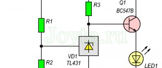
Simple indicator circuit
A circuit using transistor elements and resistances is used in indicators operating with direct and alternating voltages up to 600 volts. This design is somewhat more complicated than an indicator screwdriver, but the addition of parts makes the LED voltage indicator a universal tool. It can be used completely safely to test voltages ranging from 5 to 600 volts.
In the presented diagram, field-effect transistor VT2 is clearly visible, which serves as the basis for the entire design of the indicator. The operation of the device depends on the threshold voltage value fixed by the potential difference in the gate-source position.
The value of the maximum possible network voltages depends on the potential drop in the drain-source position. At its core, this transistor is a kind of current stabilizer. Transistor VT1 is bipolar, used for feedback and support of specified parameters.
A homemade indicator functions as follows. When voltage is applied to the input, an electric current appears in the circuit. Its value depends on the resistance R2 and the voltage of the bipolar transistor VT1 in the base-emitter junction. Lighting of a low-power LED is quite possible with a stabilizing current of 100 µA. When the base-emitter voltage is about 0.5 volts, the resistance of R2 should be in the range from 500 to 600 ohms. The LED is protected from possible current surges by a non-polar capacitor C, the capacitance of which is 0.1 µF.
The power of resistor R1 is 1 Mohm, which is quite enough to use it as a load for transistor VT1. When operating with constant voltage, the VD diode performs a protective function and checks the poles. When AC voltage is tested, this diode becomes a rectifier and serves to cut off the negative half-wave. The magnitude of its reverse voltage is at least 600 volts. The HL LED itself should be selected with the highest brightness so that the signal is noticeable even with minimal current.
Why do you need a speed controller?
An engine speed controller, a frequency converter, is a device with a powerful transistor, which is necessary to invert the voltage, as well as to ensure smooth stopping and starting of an asynchronous motor using PWM. PWM – wide-pulse control of electrical devices. It is used to create a specific sinusoid of alternating and direct current.
Photo - a powerful regulator for an asynchronous motor
The simplest example of a converter is a conventional voltage stabilizer. But the device under discussion has a much wider range of operation and power.
Frequency converters are used in any device that is powered by electrical energy. Governors provide extremely precise electrical motor control so that engine speed can be adjusted up or down, maintaining revs at the desired level, and protecting instruments from sudden revving. In this case, the electric motor uses only the energy needed to operate, instead of running it at full power.
Photo – DC motor speed controller
Why do you need a speed controller for an asynchronous electric motor:
- To save energy. By controlling the speed of the motor, the smoothness of its start and stop, strength and speed, you can achieve significant savings in personal funds. As an example, reducing speed by 20% can result in energy savings of 50%.
- The frequency converter can be used to control process temperature, pressure or without the use of a separate controller;
- No additional controller required for soft start;
- Maintenance costs are significantly reduced.
The device is often used for a welding machine (mainly for semi-automatic machines), an electric stove, a number of household appliances (vacuum cleaner, sewing machine, radio, washing machine), home heater, various ship models, etc.
Photo – PWM speed controller
General structure and principle of operation
Light indicators are signs that operate on the basis of a light source. LED devices operate by emitting light from a pn junction when current passes through it.
In everyday life, portable indicating devices are used, including multimeters. The main purpose is to determine the presence/absence of current and the difference in voltage values. The voltage depends on the type of device; by design, the indicators are single- and double-pole. In the first option there is one current-carrying part, in the second – two.
Stores sell simple testers in the form of pens and screwdrivers. The structure is housed in a dielectric housing with a viewing window. Main elements: LED and resistor. There is a probe on the bottom and a metal contact on top for touching by hand.
These devices allow:
- determine zero and phase;
- voltage on safety equipment.
Single-pole screwdriver testers are divided into:
- passive;
- with additional functions;
- with extended functionality.
A passive tester is used to determine the presence of voltage in electrical equipment and wiring. A flathead screwdriver is used to make contact; resistance is created by a circuit in the handle. The LED lights up when you touch a part through which current flows.
Advantages of a passive screwdriver:
- simple design;
- no power supply required;
- no special knowledge required.
There are two drawbacks: the dim glow of the LED and the need to remove gloves during testing.
The device with additional functionality can be used in two modes: contactless and contact. The presence of voltage is determined, and wires, cables, and fuses can be checked. This tester is powered by batteries. Zero and phase are determined in the same way as with a passive screwdriver. When testing using the non-contact method, the device is held without touching the bottom. The upper part is brought to the conductor.
Digital indicators with advanced functionality. It is impossible to do something like this on your own.
Most two-pin indicators are professional. In terms of functionality, they are almost no different from single-contact ones. These devices are equipped with two probes with sharp pins at the ends. During testing, you can find out the voltage value (the parameter is displayed on the screen).
What it is
An electrical tester is a device that is used to measure and determine the voltage in an electrical circuit. The main difference from a multimeter is the simplicity of the design and use of this unit; it operates quickly and can be used in any conditions.
Photo - resistance tester
There are also more compact probe testers that can be used to measure the voltage level in an outlet or any other electrical device, for example, generators in a car. They differ from standard indicators in their small size, and they also have simpler operating instructions.
Previously, a pointer tester, such as ASKOM, was mainly used. It has a reliable operating circuit, is powered by batteries and provides fairly reliable and accurate operation.
A few words about the containers around us
How does a capacitive voltage indicator work? To understand this, let's go back for a moment to electrical circuit theory and remember how a capacitor functions. It has two conductors, or plates, separated by a dielectric. Many people think that capacitors are separate elements of electronic circuits, but in reality the world is filled with capacitors whose presence we usually simply do not notice. Here's an example. Suppose you are standing on a carpet covering a concrete floor directly under a 220-volt light fixture. Although you may not feel it, your body is conducting very little (on the order of a microampere) alternating current because it is part of a circuit consisting of two series connected capacitors. The two plates of the first capacitor are the filament in the light bulb and your body. The dielectric is the air (and possibly your hat) between them. The plates of the second capacitor are your body and the concrete floor (it is a fairly good conductor).
The dielectric of the second capacitor is the carpet plus your shoes and socks. Since the concrete floor is well grounded, as is the neutral wire of the power supply network, a voltage of 220 V is applied to the circuit of these two series capacitors.
Terms of use
When starting to work with a voltage indicator, you need to make sure that it is intact and operational. The potential difference for which it is intended must be higher than the operating voltage of the electrical equipment being tested. The indicator's next laboratory test date must not be past due.
Before working with a low voltage indicator (LVI), it must be checked for functionality. To check, you can use a connected socket with a voltage of 220 V. A single-pole indicator should determine the phase, and a two-pole indicator should determine the presence of 220 V.
To check the high voltage indicator (HVI), its probe is brought closer to parts of the electrical installation to which high voltage is applied. The alarm should sound. All operations with UNN must be done with dielectric gloves.
Some work in the house can be performed by people without special training, without resorting to the services of professional electricians. Replacing sockets, switches, and repairing table and ceiling lamps do not require high qualifications.
But when performing this work, you must follow safety rules, which require checking that there is no voltage at the contacts of electrical appliances before starting work.
Single-pole voltage indicator
- the simplest and most accessible device for everyone, indicating the presence or absence of a “phase”. Some models are also used to search for breaks in wires, cords and cables. Since some single-pole indicators combine the function of a simple screwdriver, they are called “indicator screwdrivers”, and sometimes simply “indicators”.
The advantage of indicators is that they do not require a second wire to operate. They use current passing from "phase" to "ground" through the pointer and the human body, connected in series. This current does not pose a danger to humans. It is not hampered by the resistance of shoes or the floor material, but you cannot use the pointer while wearing dielectric gloves; it will not work. In practice, there were isolated cases when the indicator screwdriver did not detect the presence of a “phase” in the lamp if the electrician was standing on a dry wooden stepladder.
Manufacturing Guide
You can assemble a circuit using a light or sound indicator for your car at home. If you have experience in electrical engineering, this task will not take much time. But even if you have never done such work before, there is nothing difficult about it. The main thing is to correctly connect all the elements of the circuit and connect them to the on-board network.
Let's look at an example of assembling an indicator to determine the voltage of a car battery. Instead of the ten individual diode elements that are marked in the diagram, we will use a solid indicator since it does not take up much space.
What will you need?
What to prepare before starting the process:
- the circuit itself, in our example we use LM 3914;
- diode strip designed for 10 segments, you can use Kingbright DC-763HWA;
- power supply adjustable from 10 to 15 volts;
- resistors.
Stages
Let's briefly look at the instructions for making the device:
- First of all, the printed circuit board must be cleaned of dust. Make sure that this component is clean and there should be no signs of burning, otherwise this may lead to the device not working in the future.
- On a ready-to-use board, all components must be assembled in accordance with the diagram shown. To solder elements, use a soldering iron with consumables. Without exception, all components of the device must be fixed as firmly as possible. If the fastening of the resistors and diode strip is weak, then the structure may become loose over time as a result of vibrations, and accordingly, the performance of the device will be impaired.
- For greater convenience and to ensure a more compact assembly of the device, the right resistor element must be cut off.
- After all components on the board are installed, the system is configured. To do this, you need to apply a voltage of 10.5 volts to the board and adjust the right trimmer. You need to ensure that the first diode strip on the device turns on.
- Then you need to apply 15-volt voltage to the device and adjust the device so that the last strip on the board starts to light. Remember that not all strips should light up, but only one of them.
- Next, all you have to do is install the manufactured device in any place convenient for you and connect it to the on-board network. In particular, if you were making a device to determine the battery charge, then it would be better to connect it to a section of the circuit that is connected directly to the battery.
- To make sure that the device is functioning correctly, you need to use a multimeter to check the charge of the battery itself. Then compare these numbers with the division on the scale of the 10-segment indicator. If the battery charge is full, then the last bar should light up, if it’s medium, then the diode light in the middle of the indicator, and if the charge is minimal, then the first light.
Board for assembling the device
Price issue
If you want to install a voltage indicator in your car, you can buy a ready-made digital device. The cost of a more or less high-quality device will start from 250 rubles. On the market you can find options whose price is 1,500 thousand rubles, but such digital devices are additionally equipped with various regulators, for example, temperature in the cabin.
How to determine the phase
The question is very simple, however, many simply do not know the answer to it. If you have any voltage indicator, even the simplest one, after reading the instructions for it you can easily figure out what’s what. In the case of a simple indicator screwdriver, you just need to insert it into the socket and touch the contact - if the light comes on, you have found the phase, if not, you have determined zero.
For a screwdriver to work correctly, it must contain a resistor with a resistance of one megaohm. If the screwdriver is from the Middle Kingdom, this part of it will be made in the shape of a grayish cylinder.
Despite its simplicity, a screwdriver with a voltage indicator helps out in the simplest and most banal situations, and is especially indispensable in everyday life.
If you are working with a liquid crystal modification, you need to know that when checking the system voltage with a load below 50 volts, you need to touch a special touch panel.
If the voltage is much higher, but does not exceed 500 volts, then you should not touch the sensor. Such indicators do not have a special LED, therefore, to check the indicators, you need to bend over to it, and sometimes highlight it with something.
Simple homemade products for a car, tips for car enthusiasts and do-it-yourself diagrams
This mode allows you to measure the voltage in wires plastered in the wall, as well as identify their route.
3 thoughts on “Battery indicator on LEDs circuit for beginners”
When the input voltage is 0, this indicator is considered one of the essential tools of an electrician.
Having gouged the wall, I pulled out the old wire and was about to install a new one, but I decided to check it again. Let's connect one probe to one socket of the socket, and the second to the second. Or assemble a simple “blinker” yourself using two bipolar transistors. Which is better to choose? All devices have their pros and cons, which must be taken into account when purchasing them. When a screwdriver is connected unipolarly to a current-carrying phase conductor and a finger touches the touch pad, the neon lamp will light up, signaling the presence of mains voltage. The LED is connected in series with the battery through a field-effect transistor channel.
Logical level indicator probe on four transistors To indicate fine tuning, radio receivers often use simple devices containing one, and sometimes several, LEDs of different colors. For such purposes, it is better to use a multimeter in dialing mode. This turns out to be sufficient for the human eye to normally perceive light from the LED as continuous radiation. Methods for controlling the state of an LED using transistor switches Fig. sxematube - circuit of a simple voltage indicator more or less, simple circuit of a voltage indicator
Instructions for operating the indicator UVNU-10SZ IP
The high voltage indicator UVNU - 10SZ IP and the phasing tube consist of 2 main parts: a working part and an insulating part with a handle. The links are connected to each other by screwing. Safety when working with the pointer and phasing tube is ensured by a ring-shaped stop on the body.
Before use you should:
Carry out an external inspection of the pointer and phasing tube, during which you should pay attention to the absence of cracks, peeling and other defects.
If there is moisture or dirt, remove it with a cloth. If the indicator fogs up in a warm room after storage or operation in the cold, it is necessary to keep it in this room for 15 minutes and wipe it dry with a napkin.
Before using the pointer, you must ensure that it is in good working order.
To do this, touch the probe (hook) with one hand (without gloves) and press the button on the end of the working part of the pointer with the other. Intermittent lighting and sound of the indicator indicate its serviceability.
If the skin resistance is high and the self-test does not work, you need to moisturize your fingers.
At low temperatures (below -25°C), if the self-test does not work, it is recommended to check the indicator as a voltage indicator on an installation that is known to be energized or using a special device for testing voltage indicators (UPUN).
When using the pointer as a voltage indicator from 100 to 1000 V, it is necessary to touch the metal parts of the tail of the working part with your hand and bring the probe (hook) to the current-carrying wire. The appearance of intermittent light and sound signals indicates that the current-carrying part is energized.
Phase-by-phase determination of the presence of voltage is carried out by contact method.
The operator needs to climb onto the support, or determine the presence of voltage by touching the current-carrying part from the ground, if there is an operational insulating rod ШО - 10 - 4 - 6.6, 6.6 m long; in this case, the working part of the pointer is fixed to the thread of the operating head of the rod.
When the probe (hook) touches the pointer to a live part that is energized, bright red flashes simultaneously appear with a frequent intermittent powerful sound signal.
To determine the presence of induced voltage on a de-energized and grounded electrical circuit. installation, you must first check the presence of voltage with a pointer.
After making sure that there is no voltage, it is necessary to re-check the presence of an induced voltage below the threshold (1.5 kV). To do this, it is necessary to separate the working part of the indicator from the insulating part, touching the metal parts of the tail of the working part with your hand (without gloves), and bring the probe (hook) to the current-carrying wire.
The presence of an indication and a sound signal indicates that the current-carrying part is under induced voltage.
When using an indicator with a phasing tube, it is necessary to connect the indicator to the phasing tube with the wire included in the delivery set, and insert the pin of the shunt wire into the hole made on the side of the working part of the indicator.
To avoid damage, the pointer should not be subjected to impacts or shocks.
DC Voltage Check
The indicator circuit we considered can be used not only in AC circuits, but also in DC circuits. If we touch the “plus” with a probe attached to the anode of the LED, and with another probe we touch the “minus” of the electrical installation, the indicator will light up. If the indicator is connected in the opposite direction, the LED will not light up. Thus, we will not only be able to check the presence of voltage, but also determine the polarity of the source.
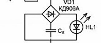
The simplest LED voltage indicator circuit can be improved. To do this, you need to make one change to it: replace the silicon diode with an LED. After this replacement, both LEDs of the indicator connected to alternating voltage will light up simultaneously. When checking for constant voltage, one of the LEDs will light up. Which LED will light depends on the polarity of the indicator connection.
If the indicator can glow in different colors, then by default green LEDs indicate normal operation, such as correct polarity.
Checking the grounding of household appliances
Washing machines, microwave ovens, refrigeration units - for safe operation they must be grounded. To verify this, touch the probe to the body of switched household appliance. There is no grounding if the LED lights up.
The light is on - there is no grounding
How to find wiring under plaster?
There is a separate article about this on Domovushkin.ru, where all possible methods are discussed. Here I’ll just note that a simple screwdriver is not suitable for searching. Need a universal or active one. The one that lights up when you press it at both ends. And success is not guaranteed if the wires are hidden deep or there are fittings in the wall.
How to proceed:
- Grasp the dipstick.
- Direct the opposite part towards the wall.
- Drive to the location where the cable is supposed to be located.
A glowing diode will indicate the presence of a live cable if it is not buried too deeply.
How to detect current leakage?
If the insulation is broken or a breakdown occurs, a leak occurs on the metal casing of household appliances. To protect yourself from damage, use an indicator screwdriver.
Carefully touch the surface of the unit when it is turned on. If the LED lights up even a little, this is a clear sign of a leak. You need to find insulation damage and check the grounding.
Types of voltage indicators
Voltage indicators are:
- with neon lamp;
- with LEDs, battery operated;
- with liquid crystal display;
- contactless;
- multifunctional.
Signs with neon lamps are the cheapest
. Their disadvantages are low ignition voltage and insufficient brightness. In bright light, you have to cover them with your hand to see if the lamp is glowing.
LED indicators have a lower ignition threshold.
The presence of a battery allows you to use them to “test” circuits and use the pointer as a contactless one. If you take the tip of an indicator screwdriver and bring its end to a live wire, the light will light up. But if it does not light up, this will not be evidence of a lack of voltage.
The disadvantage of LED indicators is that they glow due to interference in the circuit being tested, showing a “phase” where there is none.
A common drawback of neon and LED signs is the presence of a spring, which weakens over time. The contact inside the indicator is broken and it stops working.
Indicators with displays and non-contact voltage indicators do not have this drawback. For indicators with displays
Same sensitivity as LED. But they recognize interference in circuits, indicating on the display a voltage value lower than 220V. But their readings are not visible in the dark.
Contactless signs are battery operated.
If you turn them on and bring them to a phase conductor, they emit light and sound signals. This is convenient when checking the complete absence of voltage, but is not applicable in cases of determining the “phase” on conductors located close to each other. For this you need a contact pointer.
Multifunctional indicators
are a multimeter that combines the functions of an ohmmeter, voltmeter and non-contact pointer.
Each of the pointers has advantages and disadvantages. When choosing a voltage indicator for your own needs, remember: a good indicator is the one you use. The main thing is to learn to correctly understand the pointer signals.
Two-pole voltage indicator
This type of pointer has two parts, separate from each other. They are made using a dielectric material and an insulated flexible copper conductor that connects two separate parts.
The operating principle of a two-pole indicator is completely simple; you just need to lightly touch the conductive parts with the poles and the device will show whether there is voltage or not.
The current flowing through the lamp is only a few milliamps, but this is quite enough for a stable light signal. To prevent an increase in voltage in the lamp, you need to connect a regular resistor to it.
In addition to the manufactured indicators, you can use similar devices - indicators, which also serve to determine the voltage in the electrical network and are equipped with a special scale backlit by LEDs on the body and calibration of certain voltage readings from 12 to 750 V.
