Discipline: Operation of electrical network equipment
Lecture No. 13. “Maintenance of capacitor units from 0.22 to 10 kV and coupling capacitors 35-220 kV”
13.1 Purpose of capacitor units. 1
13.2 Operating modes, voltage levels. 2
13.3 Features for implementing safety measures when servicing the KU.. 3
13.4 Technical documentation. 5
13.5 Inspections, major and current repairs.. 5
13.6 Operation and ensuring reliable operation of coupling capacitors 35-110 kV 6
13.7 Preventive tests of capacitors. 6
Purpose of capacitor units
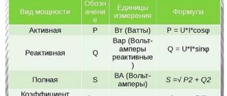
The cheapest and at the same time the most effective means of increasing the technical and economic performance of electrical systems is reactive power compensation. The concept of reactive power sources (RPS) usually refers to any devices capable of purposefully influencing the balance of reactive power in the electrical power system. In power supply systems (PSS) of industrial enterprises, IRM is used to compensate for the reactive power consumed by a powerful, abruptly variable load, and to balance the load. The second group of IRMs includes static reactive power compensators - capacitor banks (CB). Capacitor banks can only regulate the power they generate in steps. For their switching (switching on, switching off), ordinary contactors are used in networks up to 1 kV, and switches are used in networks 6 - 10 kV and above. The main role of capacitor units in industrial networks is to reduce electricity losses in networks and regulate voltage within acceptable limits. The power generated by the KB, for a given capacity C, is proportional to the square of the applied voltage and its frequency QKB = U 2 wC. Therefore, unregulated CBs have a negative regulatory effect. This means that the power of the CB decreases with a decrease in the applied voltage, whereas under the conditions of the regime this power must be increased.
Modern capacitor installations allow long-term operation when the effective value of the voltage between the terminals increases to 1.1 U nom, network. They ensure long-term operation without reducing service life when the effective current value increases to 1.3 I rated, both due to an increase in voltage, and due to higher harmonics, or due to both, regardless of the harmonic composition of the current. Taking into account the maximum deviation of the capacitance, the maximum permissible current can be up to 1.43 I rated capacitor. The use of capacitor units, which are the most common means of reactive power compensation in industrial networks, makes it possible:
— increasing the power factor to the required value;
— reducing electricity losses in elements of the power supply network;
— voltage regulation at various points of the network;
— improving the quality of electricity.
Their use allows:
— ensure high accuracy of the specified power factor;
— maintain optimal reactive power compensation mode depending on the load;
— reduce heat losses in distribution networks and electricity costs;
— reduce the influence of higher harmonic current components on electrical equipment;
— unload equipment of substations and distribution networks, increase its service life.
The requirements below apply to capacitor units with a voltage from 0.22 to 10 kV and a frequency of 50 Hz, intended for reactive power compensation and voltage regulation and connected in parallel to the inductive elements of the electrical network. The capacitor installation must be in a technical condition that ensures its long-term and reliable operation. Control of a capacitor installation and regulation of the operating mode of capacitor banks should, as a rule, be automatic. The control of a capacitor unit, which has a common switching device with an individual electrical energy receiver, can be carried out manually simultaneously with turning on or off the electrical energy receiver. In addition to power capacitors used to compensate for reactive power, coupling capacitors, power take-off capacitors, and capacitors for voltage dividers are used in the electric power industry , capacitors for improving power factor, capacitors for longitudinal compensation units and capacitors used for surge protection.
Operating principle
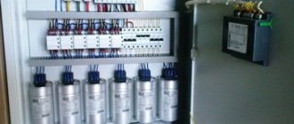
The design of the capacitor unit is made in the form of an electrical appliance consisting of a capacitor and additional electrical equipment. This installation is designed to compensate for the reactive power of equipment, which creates electromagnetic fields and additional load on electrical appliances.
Various devices are used to regulate the load, including capacitors, contactors, controllers and protective equipment. With their help, each capacitor installation can easily compensate for reactive power. They are quite simple to install and operate, operate almost silently, and help reduce losses in cable lines.
The operating principle of capacitor units is based on the effect of dynamic or switched reactive power compensation. For this purpose, a special system of capacitors arranged in a certain sequence is used. Direct switching is carried out using contactors or thyristors. The first option is used in most capacitor installations with electromechanical relays. They have a universal design, are easy to use, and are relatively inexpensive.
The second option using thyristor systems is considered more expensive, but it has proven itself well in networks with sharply changing loads. Any device can be connected to any part of the electrical network, regardless of the principle of operation.
Typical connection diagrams for UKRM
To increase the power factor in electrical networks, reactive power compensation devices are used. UKRM is an excellent tool for implementing energy saving programs and reducing reactive power consumption.
Reactive power compensation is relevant mainly for industrial facilities where a huge number of electric motors are used.
There are both automatic and unregulated condenser units. Preference should be given to ACU.
By the way, I have a program for calculating the capacitance of a capacitor unit.
A prerequisite for automatic reactive power compensation is the presence of an external measuring current transformer that measures the phase current consumption of the load that is supposed to be compensated. In some cases, a summing current transformer is used to sum current signals from several external ICTs for one PFC. With this method of connection, external ITTs must be installed in the same phase at the inputs, and their transformation ratios must be the same.
Let's consider the main connection diagrams for UKRM in a conditionally symmetrical 0.4 kV network. In such a network, it is enough to control the current in one phase.
1 Individual reactive power compensation.
Individual reactive power compensation
In this scheme, the power part of the PFC is connected directly to the terminals of a large RM consumer (or in close proximity). External ITT (TA1) is installed on one of the consumer input phases.
2 Group reactive power compensation.
Group reactive power compensation
With group compensation, the power part of the control gear is connected to the buses of the group assembly (ShR, ShchS, etc.). External ITT (TA1) is installed on one of the input phases of the group board.
3 Group reactive power compensation when powered from 2 inputs.
Group reactive power compensation when powered from 2 inputs
To implement this circuit, two measuring current transformers and a summing current transformer are used. External ICTs (TA1 and TA2) are installed on one of the input phases of the group board. To summarize current readings from external ICTs, a summing CT (TA3) is used. The transformation coefficients of external ITTs (TA1, TA2) must be the same.
4 Centralized reactive power compensation.
Centralized reactive power compensation
Perhaps one of the most common reactive power compensation schemes. External ITT (TA1) are installed on one of the input phases of the 0.4 kV bus section.
5 Centralized reactive power compensation with two supply transformers.
Centralized reactive power compensation with two supply transformers
Supply transformers can operate either individually or in parallel. External ICTs (TA1, TA2) are installed on one of the input phases of the 0.4 kV bus section. To match the current signals, a summing CT (TA3) is used; the transformation ratios of the ICT TA1 and TA2 must be the same.
6 Centralized sectional reactive power compensation with two supply transformers.
Centralized sectional reactive power compensation with two supply transformers
In this scheme, two bus sections are implemented with two supply transformers (T1, T2) and an active sectional switch (QS3). External ICTs (TA1, TA2) are installed on one of the input phases of the 0.4 kV bus section, as well as on the intersectional connection (TA3, TA4). To match the current signals, summing CTs (TA5, TA6) are used; the transformation ratios of the ICTs TA1 - TA4 must be the same.
I think now you will have fewer questions when designing objects that require reactive power compensation.
I recommend reading:
How to connect an electric energy meter?
Connection diagram of a single-phase generator to a three-phase network
Installing a switch at the input of the supply line
Control circuit for outdoor lighting, advertising, backlighting
Purpose of KRM settings
Capacitor installations are also known as KRM installations - that is, reactive power compensators. They are widely used in power generation, transformers, induction motors and other equipment with emerging reactive power. This phenomenon causes certain troubles for connected equipment due to the creation of additional voltage in the network. Installations that compensate for reactive power are designed to reduce negative consequences.
Very often the question arises: why is a capacitor unit needed? What is this device used for? The main function of these systems is to maintain a given level of consumer power factor. For this purpose, load changes are monitored in real time, after which the required number of capacitor banks is turned on or off at the right moment.
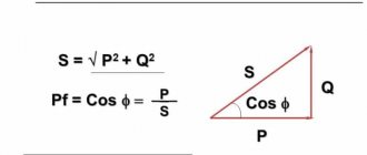
Most of the load on modern electrical networks is generated in industrial enterprises by electric motors, transformers and other equipment with electromagnetic systems. For their operation, reactive energy is used, under the influence of which a phase shift appears between current and voltage. When the load is turned on, not only active but also reactive energy is consumed. In this regard, the total power increases by an average of 20-25% relative to the active power. This ratio will be the power factor.
In order to prevent reactive power from entering the network, various types of capacitor units are used. Due to this, it is produced and remains in place, where it is consumed by electrical loads.
There are several types of reactive power compensation units: automatic high-voltage and low-voltage, thyristor, filter-compensating units, as well as thyristor units with filtering of higher harmonics. Separately, it should be noted that capacitor units are unregulated, compensating the reactive power of constant loads. Typical examples of such equipment are various types of pumps, especially used in heat and water supply systems. In this case, the power factor is improved by applying constant capacitor power directly to the reactive load.
Purpose of the reactive power compensation device
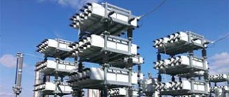
Rice. Appearance of UKRM 6(10) kV
The main purpose of the device is to reduce the effect of reactive power and serves to increase and maintain at a certain standard level the value of the power factor in three-phase distribution networks. The main purpose of UKRM is the accumulation of reactive power in capacitors. This action helps to relieve the electrical network from reactive power flows, voltage stabilization occurs, and the share of active power increases.
Advantages of using capacitor units
The main positive qualities of compensation systems are the absence of any rotating parts, small specific active power losses, the ability to select any practically necessary compensation power, the ability to connect to any point in the network, simple operation and installation, absence of noise during operation, and relatively low capital investments.
Capacitor units come in two versions:
- Modular - used to compensate reactive power in group networks and power supply networks at large and medium-sized enterprises.
- Monoblock - are widely used for reactive power compensation in group networks at small enterprises.
If the enterprise operates around the clock and the generation of reactive energy occurs constantly, then it is beneficial for the capacitor units to operate around the clock. But if in production, the work is distributed unevenly, let’s say the load decreases significantly at night, it is necessary to ensure that they are turned off, since continuous operation can lead to an unnecessary increase in voltage in the electrical networks.
Installations with automatic adjustment are more suitable for such production. They have an automatic regulator, it constantly monitors the power factor value, and regulates the number of connected batteries, which allows for maximum compensation of its volume.
Energy efficiency of industrial electrical networks
Relatively recently, there was no need for such equipment. However, now there are practically no specialists left who think about what capacitor units are needed for. The problem of shortage of high-quality electricity is too obvious.
The number of consumers is growing exponentially, industrial equipment is becoming more and more sensitive to electricity parameters, but obsolete networks cannot cope with the load either in terms of qualitative or quantitative characteristics. During the transportation of electricity and the operation of many installations, not only active but also reactive power is generated. Part of the system's power is wasted, increasing the cost of transporting the resource, increasing its consumption and overloading the system. Electrical networks with reactive power are characterized by heating of individual elements, breakdowns and overloads.
To avoid negative consequences, it is necessary to invest heavily in upgrading networks: increasing the cross-section of cables, installing transformers and other equipment of increased power. However, there is a simpler and more effective solution.
Capacitor units have a number of advantages:
- Provide a noticeable effect at low start-up costs. With the right approach, each installation pays for itself within a year.
- Extremely easy to install and operate.
- Connect exactly where you need it.
- There are solutions for low, medium and high voltage power networks.
Purpose of capacitor units
Depending on the customer’s requirements, control units solve the following problems:
- Reduce consumption and cost of electricity consumed.
- They guarantee the transfer of resources through wires of a smaller cross-section, without expensive modernization of the entire electrical network.
- Stabilize current parameters during transportation over long distances. Prevent voltage surges on electrical networks of various sizes.
- Protect equipment from overloads.
- Increase the quality of the supplied resource.
The most effective HRSGs are in industries with a high content of asynchronous motors, power plants with cos φ = 0.7 and below, etc.
Operating principle of a capacitor unit
The operation of the KU is based on the effect of switched or dynamic compensation of reactive power by a system of capacitors located in a certain sequence. For switching in a capacitor installation (the principle of operation is slightly different in each of the indicated subtypes), contactors or thyristors are used. In the first case, switching occurs due to an electromechanical relay, which is typical for the vast majority of control units. Their advantages include low cost, versatility of design and ease of use. Thyristor systems are somewhat more complex, but in electrical networks with sharply variable loads they have a number of advantages.
However, whatever the principle of operation of the capacitor installation, they can be connected at any part of the network (at the input of enterprises, for a group of similar installations, near a single consumer, or in a mixed scheme).
Main functions of UKRM
- Reducing the consumed load current by 30-50%.
- Reducing the components of the distribution network, increasing their service life.
- Increasing the reliability and capacity of the electrical network.
- Reducing thermal losses of electric current.
- Reducing the impact of higher harmonics.
- Reducing phase unbalance, smoothing network noise.
- Minimize the cost of inductive power.
The UKRM reactive power compensation installation has a number of advantages due to the use of capacitors, supplemented by a third level of safety in the form of a segmented polypropylene film impregnated with a special liquid, ensuring reliable use, durability, and low cost when performing maintenance and repair work.
The presence in the UKRM capacitor installation of specialized thyristor high-speed starters, operating with a time advance for switching phase capacitors that are triggered when cosφ changes, extends their trouble-free operation.
Rice. Appearance of a thyristor for switching capacitor units.
To ensure regulation of cosj in automatic mode with transmission of information to a PC with control of higher harmonics of current and voltage in the network, controllers with contactor switching are used.
To improve the quality of operation of the UKRM, the installation contains an odd harmonic filter and thermal regulation devices, and an indication system has been designed to detect faults.
All equipment is placed in a block container equipped with ventilation and heating with automatic control. The devices provide comfortable and convenient maintenance at low temperatures down to -60o C.
The modular type of construction contributes to the gradual increase in the capacity of the UKRM.