4 / 5 ( 3 voices)
A voltage relay is necessary to protect the electrical network from voltage surges. Currently, the issue of stable voltage in the electrical network is quite acute.
Instagram https://instagram.com/elektroschyt VKontakte https://vk.com/elektrika46
Network organizations are in no hurry to reconstruct and modernize power lines, substations and transformers. Meanwhile, the situation is only getting worse, so voltage fluctuations in our networks are quite common.
For those who still doubt the installation of a relay to protect their home or believe in the quality of construction and installation work in modern new buildings. Below is a screenshot of one of the latest comments, where the author writes that he had a “zero burnt out” in his new building.
According to GOST 29322-92, the voltage in the electrical network of our country should be within 230 V in one phase and 400 V between phases. But if you live in a rural area or near a city, then problems with constant voltage levels are very high, and in the city itself this cannot be ruled out, especially in older housing stock. Voltage surges have a very detrimental effect on electrical appliances in the house. For example, due to low voltage, a refrigerator or air conditioner may burn out (the compressor will not start and overheat), the power of the microwave is greatly reduced, and incandescent lamps glow dimly. Well, high voltage will simply “kill” your household appliances. I am sure that many have heard about “zero burnout” in high-rise buildings, and how entire hallways are taken to workshops to repair household appliances.
The reasons for voltage fluctuations in the network are different:
- Shorting one of the phases to neutral, the result will be 380 Volts in the outlet.
- Burnout (break) of zero, if you have a low load at this time, then the voltage will also tend to 380 V.
- Uneven distribution of load across phases (misalignment), as a result, the voltage decreases in the most loaded phase, and if a refrigerator and air conditioners are connected to it, there is a high probability that they will “burn out.”
Example video showing the operation of a voltage relay
Special devices - voltage control relays - help solve the problem of voltage surges in networks. The principle of operation of such relays is quite simple, there is an “electronic unit” that monitors that the voltage is within the limits specified by the settings and if there are deviations, it signals the release (power section), which turns off the network. All household voltage control relays turn on automatically after a certain time. For ordinary consumers, a delay of a few seconds is sufficient, but for refrigerators and air conditioners with compressors a delay of several minutes is needed.
Here is the link for a detailed article about the RN-260t voltage relay from Novatek-Electro.
Voltage control relays are available in single-phase and three-phase types. Single-phase voltage relays disconnect one phase, while three-phase voltage relays disconnect all three phases at the same time. When using a three-phase connection at home, single-phase voltage relays should be used so that voltage fluctuations on one phase do not lead to the shutdown of other phases. Three-phase ones are used to protect motors and other three-phase consumers.
I divide surge protection devices into three types: UZM-51M from Meander, Zubr from Electronics and all the others. I am not imposing anything on anyone - this is my personal opinion.
Voltage relay Zubr (Rbuz)
This device is designed to protect against voltage surges (zero burnout). BISON is produced in Donetsk.
I will note the features of this voltage relay.
Voltage indication on the device – shows the voltage value in real time. This is quite convenient and necessary for assessing the voltage situation in the network. The reading error is low, the difference relative to the Fluke 87 high-precision multimeter is only 1-2 Volts.
Zubr voltage relays are produced for various rated currents: 25, 32, 40, 50 and 63A. The device, with a rated current of 63A, can withstand a current of 80A for 10 minutes.
The upper voltage value is set from 220 to 280 V in steps of 1 Volt, the lower - from 120 to 210 V. The restart time is from 3 to 600 seconds, in steps of 3 seconds.
I set the Zubr relay, the maximum (upper) voltage value is 250 Volts, and the lower value is 190 Volts.
Devices with the index t in the name, for example Zubr D63 t , have thermal protection against internal overheating. Those. when the temperature of the device itself increases to 80 degrees (for example, due to heating of the contacts), it turns off.
Zubr relays occupy 3 modules or 53 mm on a DIN rail and are only single-phase.
The passport and the Zubr connection diagrams provided do not say about current limitations, but in the old documentation it was previously indicated that no more than 0.75 of the nominal.
Entry 1
The customer has 4 inputs for two buildings, they all have differences, I will draw the attention of readers throughout the article.
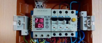
First input. In the electrical room I saw this picture:
1 – electrical panel
At the top left is a panel with an input switch, a three-pole D80 circuit breaker.
More details about the inside of the shield:
1 – electrical panel interior
Above – Three-phase meter Energomera, digital voltmeter Digitop VM-3, street-generator switch.
Read about different ways to connect a generator in my article How to properly connect a generator. It tells you how to make manual and automatic transfer of reserve (ATR).
Here's a closer look at the first row, it will be very important for us, since all the connections will take place there:
1 – Counter outputs to switch
On the switch, at the top left, there are wires (white, blue, brown), into the gap of which we will need to connect our protection relay circuit. This place is even closer:
1 – Counter-generator switch
The flexible wires on the right side of the switch are from the generator, which is installed on the roof of the building.
Despite the fact that this electrical panel was assembled by a reputable company, a gross mistake is immediately visible - pay attention to the 25 Ampere machines:
1 – Gross mistake in choosing circuit breakers
And if on the right side of the photo a wire with a cross-section of 2.5 mm² can be understood and forgiven, then six wires of 1.5 mm² will no longer fit into any gate. Here I would lower the rating to 13 or 10A, but I need to deal with the load, and that’s not what I came to this facility for. For those who are interested, I discuss this problem in detail in an article about choosing machines for an apartment panel. There are also many links to relevant articles.
Okay, let's start assembling our circuit, which I put in a separate panel:
Electrical panel assembly process 1
The wire for installation was PV1, single-core, with a cross-section of 4 mm². Or rather, VVG4x4 dissolved into sinews. I connected it into the gap through a terminal connection with a screw, I couldn’t take a photo, there will be more examples below.
Here's what we ended up with:
1 – Final view of the three-phase voltage control relay
I printed operating and setup instructions for users on the back of the cover. I will give the text below.
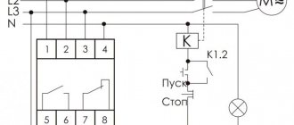
Zubr voltage relay wiring diagram
Currently, manufacturers claim that the relay can be connected at its nominal value. If the rating of the Bison is less than the rating of the input circuit breaker, then you need to use a voltage relay - a contactor - in the connection diagram.
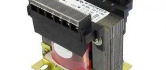
Technical data sheet Zubr D63t
The manufacturer provides 5-year warranty on the Zubr voltage ! Has very good reviews from fellow forum members. And just like Meander on the MasterCity forum there is a Zubra representative who is not afraid to communicate publicly. And by the way, it is indicative from the example of UZM and Zubr that representatives of manufacturers of quality products are not afraid to communicate on forums.
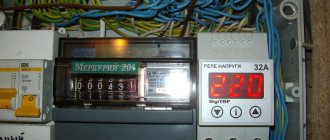
Input 4
4 – Appearance of the shield. A three-phase Barrier is connected to the gap through the screw terminal block
Closer. I think everyone understands why I use a terminal strip and do not connect directly to the meter terminals?
4 – Counter output – to terminal block
In previous versions, the panels were external, installed in electrical panels (utility rooms) and there were no installation problems. Immediately I had to make a built-in installation; I needed a drywall hacksaw.
4 – Inserting the shield into a plasterboard wall
4 – Final look
Voltage relay RN-111, RN-111M, RN-113 from Novatek
These voltage relays are manufactured here in Russia. As you can see from the title, Novatek offers three types of voltage relays.
RN-111 and RN-111M are practically the same device in terms of parameters; their main difference is that the RN-111M relay has a voltage indication, while RN-111 does not.
The upper voltage limit is from 230 to 280 V, the lower limit is from 160 to 220 V. The automatic restart time is from 5 to 900 seconds. These relays have a 3 year warranty.
How to adjust phase imbalance?
To set the interval between voltage readings on different phase conductors, press the upper and lower buttons simultaneously. The factory setting value will appear on the screen; as a rule, it is 50V. This means that the relay will stop supplying power if the voltage difference between the phases is 50V.
You can change this value by pressing both buttons at the same time, and then setting the upper or lower number to the desired number.
More details about the settings using the example of one of the models in the video:
Connection diagram for voltage relay with contactor
This significantly increases the cost, since a good contactor will now cost about 4-5 thousand rubles, you will need a larger number of modules in the panel, as well as a circuit breaker to protect the contactor coil. The above diagram for connecting a relay with a contactor for RN-111 is valid for any other relay, taking into account the features of its circuit.
Operating manual for voltage relay RN-111
Operating manual for voltage relay RN-111M
The RN-113 relay is already more improved relative to the RN-111, the voltage ranges and AR time are the same as those of the RN-111, but the maximum current for which the RN-113 can be turned on is up to 32A or if the power is up to 7 kW.
Principle of operation
The relay circuit is equipped with a special microcontroller that directly performs the tracking function and makes it possible to control the potential difference in each phase. In case of any changes on one of the conductors, this microcontroller turns on the electromagnetic relay. This operation is performed automatically. As a result, the contacts of the device open and the flow of electric current stops. When the voltage readings return to normal, the contacts close and power begins to flow into the circuit.
Connection diagram for voltage relay RN-113
But I would not do this, since the contacts on the RN-113 are weak enough for a wire with a cross-section of 6 mm2, and this is precisely the cross-section required for a 32A connection.
It is also more reliable to connect the RN-113 with contactors, without contactors for a maximum of 25A. I don’t use voltage relays from Novatek in my switchboards, so I borrowed the photo from one of the electricians from the Avs1753 forum.
It looks, of course, beautiful, but such a connection takes 3-4 more modules and is twice as expensive in cost as if UZM-51M or Zubr were used.
But what happens with the RN-113 if you connect it without 32A contactors.
Operating manual for voltage relay RN-113
Unfortunately, I did not find any information about tests like the UZM-51M and Zubr on the forums.
Relay DigiTop
Just like Zubr, these relays are produced in Donetsk. The manufacturer produces several series of devices with protection against power surges.
The V-protector series voltage relay is intended only for protection against voltage surges. Available for rated currents of 16, 20, 32, 40, 50, 63 A in a single-phase version, it has built-in thermal protection against overheating, triggered at 100 degrees. The upper threshold is from 210 to 270 V, the lower threshold is from 120 to 200 V. The automatic switching time is from 5 to 600 seconds. There is also a three-phase relay V-protector 380, quite compact 35 mm (two modules), but the maximum current in a phase is no more than 10A.
The Protektor single-phase voltage relay has a 5-year warranty, and the three-phase relay only 2 years.
Why do you need a priority relay?
The life of a modern person is surrounded by many electrical appliances. These are washing machines, boilers, air conditioners, televisions and other household radio equipment. In the kitchen alone you can find an electric stove, microwave oven, grill, toaster, electric kettle and other appliances.
In old housing stock with wiring from the last century, electricity supply to each apartment is carried out through an electric meter and a single circuit breaker. The fuse of this machine, as a rule, can withstand a current of 25 A. If you connect many electrical devices to the mains at the same time, the protection will turn off the current. Homeowners will have to constantly go to the site to the floor panel and return the machine to operating mode, since its thermal overload protection will be triggered. To avoid frequent power outages, at the entrance to the apartment’s electrical network, in addition to other standard means of protection, an additional device is built in - a priority direction selection relay.
Scope of application
The on-load tap-changer is necessary for the comfortable operation of all electrical consumers connected to one input of the power supply network with a limited power limit. This applies to apartment buildings, old mansions and housing. This problem is especially relevant for village electrical networks remote from centralized sources of electricity.
Often regional networks have limited capabilities. With high power consumption, the voltage drops catastrophically and the probability of the input circuit breaker triggering increases. In those days, when the device had not yet been invented, residents had to decide for themselves what should be manually turned off for the functioning of the necessary electrical appliances. The RPN solved this problem. Installing such a relay is advisable when the input circuit breaker is frequently turned off. An unexpected power outage can create unpleasant and sometimes even dangerous situations.
The priority relay is indispensable in those enterprises whose managers strive for maximum energy savings while maintaining the existing network power. So, for example, if a strict power limit is introduced for a certain group of consumers, then the device will turn off this particular group in critical situations.
Main settings
| Rated current, A: | |
| RT 40/P1 | 1 |
| RT 40/P5 | 5 |
| Limits of relay operation current settings, mA: | |
| Clamps 2-4, 6-8 | |
| RT 40/P1 | from 130 to 260 |
| RT 40/P5 | from 650 to 1300 |
| Clamps 5-7: | |
| RT 40/P1 | from 65 to 130 |
| RT 40/P5 | from 325 to 650 |
| Thermal stability during long-term flow of current, A, equal to | 6,93 |
| Rated frequency of alternating current, Hz | 50 or 60 |