To protect electrical equipment from interference and other electromagnetic influences, shielding is a fairly effective measure. According to GOST 30372-95, shielding is a method of attenuating electromagnetic interference using a shield having high electrical and (or) magnetic conductivity.
Physics of shielding
In the electrical power industry, frequencies of 50 or 60 Hz are used. Harmonics from them can be taken into account in the range of up to approximately 1.5 kHz when it comes to the impact on power equipment (communications will be discussed separately). The spectrum of lightning is very wide, interference to radio communications is observed up to a frequency of 30 MHz. However, the peak of the lightning strike spectrum is around 500 Hz.
At low frequencies, the model proposed by Faraday is suitable. An external electric field causes polarization within the thickness of the screen. As a result, on the surface inside the screen there are electric charges that are opposite in sign to the charges on the outer surface. As a result, the field from these charges compensates for the external electric field.
Shielding from a low-frequency magnetic field is due to the fact that, when the magnetic permeability coefficient of the screen material is much greater than 1 and the structure is sufficiently thick, the magnetic field lines pass along the screen without entering the space enclosed inside it.
It is not at all necessary that the screen be made of a solid sheet without holes. There may be holes in the screen. Moreover, it can be a cage made of electrically conductive material. This type of screen is called a “Faraday cage”. But in this case, the condition must be met: the linear dimensions of the holes or the step between the mesh rods in linear dimensions is less (ideally, much less) than the wavelength of the radiation from which the shielding is performed. Good electrical contact (ideally welding) between the cage bars is also important.
According to GOST R 51317.1.2-2007 (IEC 61000-1-2:2001) “Electromagnetic compatibility of technical equipment. Methodology for ensuring the functional safety of technical equipment in relation to electromagnetic interference”, low frequencies in relation to shielding mean frequencies below 9 kHz.
At frequencies above 9 kHz, a different model is used when considering the shielding phenomenon. If we simplify the processes extremely to make it easier to understand, the screen at high frequencies works as follows. Under the influence of external radiation, eddy currents arise in the screen. These currents create an electromagnetic field that compensates for external influences.
Insulation check
To test insulation with a megohmmeter or multimeter, the principle of continuity is the same as when searching for an electrical connection between the cable cores.
The testing algorithm is as follows:
- set the maximum range on the device - 2000 kOhm;
- connect the probes to the wires and see what the device display shows. Considering that the wires have a certain capacitance until it is charged, the readings may vary. After a few seconds, the device display can display the following values:
- one, this indicates that the insulation between the wires is normal;
- zero – there is a short circuit between the cores;
- some average readings, this can be caused either by a “leak” in the insulation or by electromagnetic interference. To determine the cause, switch the device to the maximum range of 200 kOhm. If the insulation is faulty, the display will display stable readings; if they change, then we can confidently talk about electromagnetic interference.
Attention! Before checking the insulation of the electrical wiring, it must be de-energized. The second important point is that when taking measurements, do not touch the probes with your hands, this can introduce errors.
Video: Wire continuity check - integrity check.
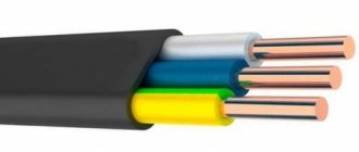
Shielded cables
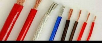
Some types of power cables have a shield. Most often, this screen is a metal tape with which the insulation of current-carrying conductors is wrapped. There are also screen options made of thick wire and a combination of thick wire and metal tape. There are known designs of cables with screens made of conductive paper and conductive rubber. It is very rare to find power cables with a screen consisting of a thin wire braid, although this design is very common for signal cables.
Section of shielded power cable for laying underground in a trench
Cable shielding is used in the following main cases:
- Cables for voltages over 2 kV, laid in the ground or in water, as well as passing in close proximity to metal structures. The presence of a screen prevents the occurrence of corona discharges between current-carrying conductors and soil (water, metal structures). Such discharges lead to destruction of the cable insulation.
- Signal cables that are sensitive to interference run near the power cable. This requirement is enshrined in PUE-7, clause 3.4.11
- Cables connecting the VFD to the motor. This is due to the fact that energy is transmitted through such a cable at frequencies of the order of tens of kHz.
Power cables laid in the ground and in water are also often metal armored. This armor is intended for mechanical protection of the cable, however, it has shielding properties. According to PUE-7, clause 3.4.11, the presence of armor or a metal sheath is mandatory for the cable connecting the secondary winding of a transformer for voltages of 110 kV and higher to the switchboard.
Methods
Testing methods depend on the purpose for which it is performed. To check the integrity of the cable for a break or electrical connection between its wires (short circuit), the continuity test can be done with a tester based on a battery and a light bulb, or you can use a multimeter for this purpose. The latter is preferable.
Despite the fact that the price of a multimeter is higher than a primitive device, we recommend buying it; this device will always be useful in the household.
The simplest device for testing an electrical cable
To check the cable, the multimeter must be turned on in the appropriate mode (diode or buzzer image).
Multimeter set to dialing mode
The testing methodology is as follows:
When checking a wire for a break, the tester is connected to its ends as shown in the figure. If the cable is intact, the light will glow (when testing with a multimeter, a characteristic sound signal will be heard).
Checking for a break
Explanations for the picture:
- A – electrical cable;
- B – cable cores;
- C – power source (battery);
- D – light bulb.
If the cable has already been laid, then on one side it is necessary to connect the wires together and ring the wires at the other end;
Second option for checking the power cable
when checking the presence of an electrical connection between the cable cores, the tester probes are connected to different wires. Unlike the previous example, there is no need to twist the wires on the other side. If there is no short circuit between the wires, the light will not light (when testing with a multimeter, no beep will sound).
Shielded conductors
At generation facilities and high-voltage substations, complete phase-shielded conductors have found their application. In them, the current conductor of each phase is enclosed in a closed continuous screen. In this case, the screen can be sealed; at high voltages, SF6 gas is pumped into it. The screens are connected at one point to the grounding circuit of the facility.
The main functions that phase-shielded down conductors perform are reducing the interaction between conductors during external short circuits, as well as eliminating heating by induced currents of nearby metal and reinforced concrete structures. Other important functions of the screen are protecting the conductor from dust and moisture, increasing the safety of operation and maintenance.
Checking cables for thermal value - an example of the work performed
Our company provides a full range of electrical measurements. Among them, short circuit testing can be noted. At the same time, the prices of the electrical laboratory are minimal - they allow you to save a huge amount of money compared to similar offers from other specialists.
Testing the cable for thermal resistance, an example of which is presented above, is carried out with the maximum level of safety. Our employees regularly undergo safety training to prevent damage to people and valuable equipment.
Below you can use the online calculator to calculate the cost of electrical laboratory services.
Requirements SO 153-34.21.122-2003
Issues of shielding for the purpose of protection from the secondary effects of lightning are considered in SO 153-34.21.122-2003 “Instructions for the installation of lightning protection of buildings, structures and industrial communications.” This document recommends the use of metal building reinforcement as a screen, if possible.
The reinforcement of a reinforced concrete building has shielding properties
When electrically connecting the reinforcement elements of an object to each other, a “Faraday cage” is obtained. It protects equipment inside the building from the electromagnetic effects of lightning strikes. The fittings, according to the instructions, must be connected to the lightning protection system of the building.
In the case where there are shielded cables inside the protected space, their shields are connected to the lightning protection system at both ends and at the zone boundaries. When laying cables between buildings, if the cable shield can withstand lightning current, additional external shielding is not required. Otherwise, to protect the cable, it is recommended to place it in a metal pipe or shielded box. The outer shield or the cable's own shield at both ends is electrically connected to the common grounding busbars of the buildings.
Single-phase power cables 6-500 kV. Calculation of grounding of screens
Recently, medium and high voltage power cables of modern designs have been widely used for the transmission and distribution of electricity, especially in large cities and industrial enterprises, where the level of power consumption and load density are very significant. The most common are single-phase power cables with cross-linked polyethylene insulation.
Georgy Evdokunin, Doctor of Technical Sciences, Professor of the Department of Electrical Systems and Networks, St. Petersburg State Polytechnic University, St. Petersburg
Mikhail Dmitriev, Ph.D., Head of the Scientific and Technical Research Department of ZAO Plant of Energy Protective Devices
The high voltage level of the cable conductor leads to the need to use a metal screen. The main purpose of the metal screen is to eliminate the electric field on the surface of the cable. To reduce the voltage on the screen, it is grounded at one or more points. About the features of grounding screens - in the material of our St. Petersburg authors Mikhail Viktorovich Dmitriev and Georgy Anatolyevich Evdokunin. Note that the given method for calculating parameters and modes can be applied both in calculations for single-phase cables of 110–500 kV, and for cables of voltages of 6–35 kV.
The method of grounding the cable shield affects:
- on electrical losses in the cable (in the screen), and therefore on its thermal conditions and throughput;
— by the voltage value on the screen in normal and emergency modes, i.e. on the reliability of the cable and the safety of its maintenance;
- on the main electrical parameters of the cable (active and inductive resistance).
The screens of cables with cross-linked polyethylene insulation are made of a highly conductive material (aluminum or copper); their grounding at more than one point leads to the appearance of significant currents comparable to the current of the cable core. If, according to the conditions for limiting the voltage on the screen, it is necessary to ground it at several points, then to reduce the currents in the screens of a three-phase group of single-phase cables, transposition of the screens can be used.
There are fairly accurate formulas for calculating the linear parameters of cables, the design of which is shown in Fig. 1, including taking into account the mutual phase-by-phase influence when they are three-phase and when installed in the ground, as well as taking into account the frequency dependencies of these parameters. The exact formulas were first given in a foreign publication [1] (in addition, they can be found in the domestic monograph [2]). The formulas are quite complex and, without special computer programs for calculating them, are inconvenient to use.
The article provides formulas for the linear parameters of cables with their simplified definition, and also provides a method for calculating currents and voltages in steady-state and quasi-steady-state modes. Analytical calculations using the proposed simplifications give good agreement with the results using exact parameters.
In addition, they are confirmed by calculations obtained from detailed computer modeling of processes in the well-known Canadian-American software package EMTP-ATP (Electromagnetic Transients Program [3]).
An important issue is to ensure protection of cable insulation from lightning and other overvoltages. To protect the “core-to-screen” insulation, standard arresters of the corresponding network voltage class are used, and to protect the “screen-to-ground” insulation, special types of surge arresters are used, installed in the ungrounded ends of the screens and in transposition nodes.
The choice of characteristics of the listed surge arresters, in particular, is based on the results of calculations of power frequency voltages on the shield insulation, which can be performed using the method proposed in the article or using EMTP. However, the issues of determining the characteristics of surge arresters are not considered here in full; they are supposed to be discussed in a special article.
SIMPLIFIED CALCULATION METHOD
Let us obtain calculated expressions for the cable parameters based on the known formulas for the intrinsic and mutual linear active-inductive resistances of a multi-wire “wire-to-ground” system located above the surface of the earth. In this case, the distance to the ground does not matter, because for calculations of modes at an industrial frequency of 50 Hz, the “return wires” are located in the ground at a depth DZ of hundreds of meters. The distance DЗ, as well as the active resistance of the earth RЗ, can be determined in a simplified manner (for example, according to Ryudenberg, Table 2, see [4]). When calculating the capacitive parameters of cables, it is assumed that they are underground, as is the case (depth does not matter here). The main notations used are given in table. 1.
When determining the cable parameters (Table 2–3), the following assumptions were made:
— the geometry of the spatial arrangement of the three-phase cable system is such that s >> r3;
- if the cable phases are located at the vertices of an equilateral triangle, i.e. in the form of a “trefoil”, then s = dAB = dBC = dAC; if the cable phases are located at the same level (“flat arrangement” dAC = 2dAB = 2dBC), then when transposing the cable cores s = dAB · dBC · dAC = 1.26 · dAB;
— we simply assume that the cable screen is such that r3 >> (r3 – r2), this allows us to neglect the finite thickness of the screen and use only its inner radius in calculations;
— we neglect displacement currents in the ground;
— we neglect the proximity effect at industrial frequency, considering the active resistance of the cores and screens as for direct current.
Voltage drops along the cable cores and screens are related to the currents in them by the following system of equations:
The system has only 6 equations for six voltages and six currents; therefore, it is necessary to specify an additional 6 quantities: voltage drops (or currents) and (or) boundary conditions. On the right side of the system (1), the factors of the currents are the cable impedances, determined by the product of the corresponding linear resistances (according to Table 3) and the cable length l.
To determine the linear longitudinal active-inductive resistance of a three-phase system of single-phase cables to direct and zero sequence currents, which are used in calculations of normal and emergency modes of network operation, it is necessary to indicate the state of the cable shield (boundary conditions) on which these parameters depend (Table 4):
After setting the boundary conditions, the required parameters from (1) are found by specifying some additional conditions that characterize the problem being solved. So, for example, if a three-phase system of voltage drops applied to the conductors forms a positive sequence system, then under the specified conditions we have every reason to believe that the currents in the conductors and screens also form a positive sequence system, and then the additional conditions will look as shown in the first row of the table. 5.
Since the desired positive sequence resistance is found by dividing the voltage drop in phase A by the current in this phase, the two specified conditions are sufficient. Similar reasoning leads to the formulation of additional conditions in lines 2–3 of Table. 5.
The final formulas for calculating the longitudinal active-inductive parameters of a three-phase cable in direct and zero sequences are given in Table. 6.
Voltages (Table 7) and currents (Table in the cable shields are determined in two design cases: in normal symmetrical steady-state operation (Table 7a) and in emergency quasi-steady mode of a single-phase short circuit in the network outside the cable (Table 7b).
Using the table 7, you can calculate the voltage on the cable screen relative to ground, for which:
— the coefficient in line 1 must be multiplied by the phase value of the voltage of the network supplying the cable (UZh);
— the coefficients in lines 2–4 must be multiplied by the length of the cable and the current flowing in its core (in normal mode this is the load current, and in emergency mode this is the single-phase short circuit current of the network).
Rice. 2. Connection diagram for the screens of a group of three single-phase 110 kV cables, 8.1 km long, with XLPE insulation
CALCULATION RESULTS
As an example, consider determining the required number of screen transposition cycles for a system of three single-phase 110 kV cables with cross-linked polyethylene insulation grade 2 x S(FL)2Y1 x 1000 RMS/185 + FO64/110/123 kV with a length of 8.1 km.
Cable parameters:
If the screen is not grounded, then according to the formulas in Table. 7 on it relative to the ground there will be 20% of the phase voltage of the network, which is unacceptable.
If the screen is grounded at only one end of the cable, then:
- in normal mode (according to the formulas in Table 7a) at the open end we obtain a voltage of 0.88 V per one Ampere of current in the core; with a current in the core of 1000 A, we obtain a voltage on the screen of 880 V, which is acceptable for insulating the screen (but unacceptable for personnel in case of the possibility of touching the screen);
— in emergency mode (according to the formulas in Table 7b) at the open end we obtain a voltage of 5.8 V per one Ampere of current in the core; even with a short circuit current of only 10 kA, we have a voltage of about 58 kV, which is unacceptable for screen insulation, i.e., obviously, the screen must be grounded at both ends of the cable.
If the cable screen is grounded at both ends, then (using the formulas in the table we obtain the current in the cable screen | iEA| = 0.8 · | iZА|, i.e. a current flows in the cable screen comparable to the current of the core, which is unacceptable, taking into account the small cross-section of the screen (185 mm2) compared to the cross-section of the core (1000 mm2).
Therefore, the cable in question requires transposition of the screens.
According to table. 8 in the case of transposition of the screens in normal operation there is no current in the screen (there is a capacitive current of several amperes). In case of an external single-phase short circuit (according to the table, equal currents flow in the shields of the three phases of the cable, each of which is approximately a third of the short circuit current flowing in the cable core of the emergency phase of the network.
From the table 7 a, b it follows that the voltage on the screen relative to the ground at the transposition node:
- in normal mode it is 0.292 V per one Ampere of core current; at a current of 1000 A we get a voltage of 292 V, which is acceptable for shield insulation;
— in emergency mode it is 0.195 V per one Ampere of core current; with a short circuit current of 20 kA, we obtain a voltage of 3.8 kV, which is permissible for screen insulation and permissible for surge arresters installed between the screen and ground in transposition nodes to protect the screen-to-ground insulation from overvoltages.
The results obtained are in good agreement with calculations performed during detailed modeling of processes in the EMTP software package. Taking into account the results of analytical and computer calculations, the required connection diagram for the screens of the considered cable with a length of 8.1 km is shown in Fig. 2.
If the short circuit current were, for example, 40 kA, the voltage in the transposition unit in emergency mode would be 7.6 kV, which is unacceptable for an arrester, the characteristics of which are consistent with the insulation strength of the screen and cannot be changed. Therefore, not one, but two cycles of transposition would be required.
CONCLUSIONS
The results of calculations of the positive and zero sequence resistances of a three-phase group of single-phase cables, as well as currents and voltages in their screens at industrial frequencies do not differ from each other by more than 10% when using simplified formulas for linear parameters compared to more accurate ones. Calculations carried out in the EMTP software package with detailed modeling of cable laying conditions and design and using cable equations with frequency-dependent parameters also confirmed the possibility of carrying out similar calculations using simplified formulas for the primary parameters of single-phase cables.
LITERATURE
1. Wedepohl LM, Welcox DJ Transient analysis of underground power transmission systems. Proc. Inst. El. Eng., 1973, vol.120, N2, pp.253–260.
2. Kostenko M.V., Kadomskaya K.P., Levinshtein M.L., Efremov N.A. Overvoltages and protection against them in overhead and cable high voltage power transmissions. – L.: Nauka, 1988. – 302 p.
3. EMTP Rule book. Bonneville Power Administration, Branch of System Engineering. Portland, Oregon 97208-3621, USA, 1986 (www.emtp.org).
4. Evdokunin G.A. Electrical systems and networks. – St. Petersburg: M.P. Sizov Publishing House, 2004. – 304 p.
5. Power cables and their application/ ed.: Lothar Heinhold. – Berlin; Munchen: Siemens-Aktienges./ Part 1, 3rd revised edition, 1990.
Shielding to protect equipment and personnel
At step-down stations and open switchgears under voltage of 300 kV and above, the level of electromagnetic radiation from the equipment is dangerous for operating personnel. In this regard, protective measures are used in the form of metal meshes, magnetic screens made of materials with high magnetic permeability, etc. The corresponding recommendations are given in clause 4.2 of PUE-7.
In modern electric power industry, a variety of communication devices are widely used. In particular, digitalization of the energy sector is impossible without them.
Electric power equipment and power lines are a source of broadband interference. For normal operation of communication systems installed at substations, it is necessary to ensure reliable shielding of low-current equipment. For this purpose, communication equipment is installed in metal cabinets connected to the general grounding circuit of the facility. Since the operation of communications equipment can be affected by interference even with a wavelength of a few centimeters, the cabinet design should not have large openings. If it is necessary to monitor the operation of communication equipment through a viewing window, the window is shielded with a conductive mesh, or conductive glass is installed in the window. These elements must have an electrical connection to the cabinet.
Shielding of communications equipment in the electric power industry is regulated by the GOST IEC 6100 family of standards, as well as by organizational standards. This shielding must protect communication equipment from spectrum components above 9 kHz, i.e. it belongs to the category of high-frequency shielding. For high frequencies the metal screen can be thin, but its high conductivity is important.
Frequency of testing during operation.
Cables with voltage 2-35kV:
a) once a year - for cable lines during the first 2 years after commissioning, and thereafter:
- Once every 2 years - for cable lines for which during the first 2 years there were no emergency breakdowns or breakdowns during preventive tests, 1 time per year for cable lines on the routes of which construction and repair work was carried out and on which emergency breakdowns systematically occur isolation;
- 1 time every 3 years - for cable lines in closed areas (substations, factories, etc.); during major repairs of equipment for cable lines connected to units, 6-10 kV cable jumpers between busbars and transformers in TP and RP ;
b) It is permissible not to carry out the test:
- For cable lines up to 100 meters long, which are outputs from switchgear and transformer substations to overhead lines and consisting of two parallel cables;
- For cable lines with a service life of more than 15 years, on which the specific number of failures due to electrical breakdown is 30 or more failures per 100 kilometers per year;
- For cable lines subject to reconstruction or decommissioning in the next 5 years;
c) It is allowed by order of the technical manager of the enterprise to establish
other values of test frequency and test voltages:
- For supply cable lines for voltage 6-10 kV with a service life of more than 15 years with a number of connecting couplings of more than 10 per 1 kilometer of length;
- For supply cable lines with a voltage of 6-10 kV with a service life of more than 15 years, on which only KVV and KVB types of terminations and locally manufactured couplings are installed, with a test voltage value of at least 4 Un and a frequency of at least 1 time in 5 years.
- For cable lines with a voltage of 20-35 kV, during the first 15 years the test voltage should be 5 Un, and then 4 Un.
6.3.8 Cables for voltage 3-10 kV with rubber insulation:
- in stationary installations – once a year;
- in seasonal settings - before the onset of the season;
- after a major overhaul of the unit to which the cable is connected.
conclusions
As we see, shielding in relation to the electric power industry is a diverse phenomenon. Its application requires highly qualified designers. For example, improperly designed shield grounding can lead not to an increase, but, on the contrary, to a decrease in the resistance of the power system to lightning strikes. That is why it is better to entrust the use of screens in a project to experienced professionals, for example, specialists from the ZANDZ.com technical center.
See also: ZANDZ SMS newsletter
5. Guide to the main parameters and types of limited...