Sections of the article:
Grounding wire - cable cross-section and grade
Grounding your home has a number of benefits. Firstly, residents will be at least somehow protected from electric shock in the event of a leak. Secondly, the operation of some electrical appliances will be safer.
As a rule, there are no problems with materials for installing the simplest grounding. This is a metal corner or fitting, as well as a ready-made modular grounding kit.
Most often, those who decide to do their own grounding in the house are wondering which wire to use. Let's say the ground electrodes are buried in the ground and connected by a metal strip.
Further, from the strip that is supplied to the house, the grounding wire extends. So, you should know what cross-section of the wire should be, and what cable can be used for these purposes. This article on the site will discuss this most important issue.
What is a ground wire
The main purpose of such a cable is to protect against indirect contact with live parts of an electrical installation. Indirect contact is indirect human contact with parts of equipment that are not normally energized, such as motor housings, transformers, or the handle of a hair dryer.
Ground wire
But due to a violation of the insulation of live parts (wires), they may become energized. It is to protect against such accidents that emergency grounding is intended.
The grounding switch must reduce the potential on the protected device to zero. As a rule, with the help of this element in electrical systems, a current is passed equal to the short circuit current. This element must be able to pass current.
At first glance, we can say that the cross-section of such a cable should be no less than that of the main working conductor, but this opinion is erroneous. Each phase cable, unlike the ground electrode, must provide long-term passage of high-rated currents. The selection of cross-section is carried out according to an elementary principle - power cables with conductor dimensions from 16 to 35 mm2 must have a protective grounding conductor thickness of 16 mm2.
Designation of conductors in electrical installations up to 1000 V
In accordance with generally accepted rules at the state level, the marking of the cross-section of conductors is determined in accordance with the standards laid down in the current GOST.
In practice, such options are considered when, to achieve optimal accuracy, a separate calculation of the cable cross-section is carried out. To determine the numerical value of the area, it is necessary to use a special formula that will take into account the short circuit current indicator, the remaining time when the protection is triggered, the type of insulation and the type of conductor laying. However, in practice this formula is not always applied.
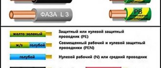
When carrying out electrical installation work, you should pay attention to the cable designation. In addition to the letter abbreviation, there is also a color designation. The neutral wire is indicated by the letter N, in blue. Combined neutral protective and neutral working conductors must have the letter designation PEN and a color designation: blue along the entire length and yellow-green stripes at the ends.
The quality of grounding plays an equally important role. To determine this characteristic, you need to measure its resistance. As a rule, the voltage in a three-phase network with a linear connection is 380V.
You might be interested Features of decorative cable
Protective conductors - their color coding
When carrying out installation work, the question of color identification of power cable cores often arises. When it is required to install a PVZ for a PE conductor in the grounding circuit, the color scheme of the insulation itself should be yellow-green. Options are being considered when the PVZ is installed as a neutral conductor, and blue insulation is selected.
Frequently asked typical questions from readers
- The electrical plug on the old Soviet water pump has been cut off. All wires are the same color. How to determine where the protective conductor is?
In principle, there is nothing complicated here; to determine the protective conductor you will need the pump itself and a multimeter (tester); if you have neither a multimeter nor a tester, but have a megohmmeter, then you can use that.To check, follow these steps:
— Strip the ends of the three conductors that come out of the pump in such a way that you can clearly touch them with the probe in turn, excluding contact of the probe with adjacent conductors.
— Then set the tester to continuity testing mode, connect the probes to the corresponding terminals of the multimeter.
— Fix one dipstick on the pump body. It is important that the installation location makes good contact, so if there is paint, a thick layer of dirt and other obstacles to the flow of electric current into the housing, they need to be cleaned or a different location chosen.
— Using the second probe, as shown in the figure below, touch each of the cores of the pump power cord one by one.
— The core that shows the circuit with the body is the protective conductor. Accordingly, the other two are the phase conductor and the neutral conductor.
This method is relevant for checking a working pump; if the insulation of the windings of an electrical machine has a breakdown to the housing, then not only the PE conductor will contact the ground.
Wire Specifications
The main indicators of PVZ can be classified into mechanical, thermal and electrical. Using the presented characteristics, you can easily determine the operability of the conductor, in particular:
- The main indicator is the flexibility of the product. The permissible radius (size) of a cable determines the amount at which a given conductor can be bent without risk of damage. The specified parameter is checked immediately after the product is manufactured.
- Temperature has a strong influence on the performance of the conductor, so when laying the product you need to pay attention to this characteristic. For example, the question often arises at what temperature a conductor of the PVZ type cannot be laid. Electrical installation work can be carried out at temperatures from -50 to +50 degrees.
The smallest dimensions of grounding conductors laid in the ground
- An emergency situation may cause short-term overheating. If problems occur, this indicator can reach +150 degrees. In addition, good insulation helps maintain dielectric and mechanical parameters.
- How many single impacts can the insulating layer withstand? This indicator is important for communication lines, as well as when working with specific equipment.
- The main property of a conductor is its insulation resistance. This parameter depends on the cross-section and temperature conditions. To check the indicator, the wire is immersed in water for 2-3 minutes. Subsequent voltage supply is 2.5 kV.
Crimping
Connecting wires by crimping is the simplest and most technologically advanced method. The wires are inserted from both sides into the sleeve and crimped with a special device called a crimper. However, this method is not suitable for connecting a wire to a ground pin. In addition, if the crimp connection is located underground, the sleeve and wires are covered with a layer of oxide, which increases the contact resistance. Sealing of such a connection is used, but in the end such sealing is a complex and unreliable solution. In fact, the rules of the PUE cannot be fully complied with. This is why crimping cannot be used for connections located underground.
Purpose and structure of the ground wire
The premises of residential, public and industrial buildings must be equipped with a protective grounding system. Before drawing up a report on the condition of the electrical wiring, the inspecting person is obliged to check the operability and safety of operation of each device.
Element structure
The grounding switch is designed to fully protect a person from electric shock. For example, if electrical contact occurs between live parts and the body of the device, there is a possibility of serious injury. Sometimes the slightest touch to such a device can lead to death or serious health consequences.
Note! To eliminate the danger described above, it is recommended that each electrical appliance be equipped with a grounding device.
How does a ground wire work?
Many people often wonder how a ground wire works. For example, if the slightest malfunction occurs during the operation of household appliances, this may be due to damage to the phase cable or the occurrence of an electric current leak. As for residents of the private sector, these areas are mainly electrified by installing overhead power lines. As a rule, these are two-wire lines that consist of phase and neutral wires.
You may be interested in Description of wire PV-1
Checking the functionality of the ground loop
Important! Gusts of wind, falling branches and precipitation can break the power cable at any time, and if the building does not have a protection system in the form of grounding and an RCD device, then not only the owner of the house, but also his household appliances may suffer.
Potential equalization system
The main potential equalization system connects the main utilities at the entrance to the building and other conductive parts of the equipment.
The system must meet the requirements of two regulatory documents:
- PUE Chapter 1.7 “Grounding and protective safety measures”
- Technical Circular No. 6/2004 “On the implementation of the main potential equalization system at the entrance to the building” -
The circular was issued to clarify some of the provisions and recommendations of the PUE in order to harmonize these recommendations with the requirements of GOST R51321.1-2000 and GOST R51732-2001. Some PUE recommendations really require clarification, since for some reason most of them are interpreted differently.
Marking of ground wires
Any electrical connection diagram contains generally accepted symbols, each of which must be deciphered for easy reading:
- A - conductor core made of aluminum. If there is no letter A on the marking, then copper was used to make the core.
- AA - designation of a stranded conductor. The core is made of aluminum material. Typically, additional aluminum braiding is used to ensure reliability.
- AC - the cable is equipped with an additional lead braid.
- B - the conductor has an increased degree of moisture resistance. Two-component steel is used to make the braid.
- BN - a distinctive feature of the braid is its resistance to fire and extreme temperatures.
- B - the outer part is made of polyvinyl chloride.
- G - conductor without sheath.
- r - the conductor cable has a moisture-proof effect.
- K - control cord, which has a wire winding.
- R - rubber is used to make the shell.
- NP - insulation includes a non-flammable polymer shell.
Protective grounding system
NYM cable
NYM category cord is in great demand among consumers. It can be used to efficiently transport electricity under standard conditions. The purpose of the cable is to transmit alternating voltage with a frequency of up to 50 Hz. Any electrical equipment can be connected to this type of cable. The cable must have the first security class. Features of NYM brand cable:
- The presence of a copper core;
- Intermediate shell;
- Color compliance with PUE standards;
- Easy to use.
NYM conductor
VVG cable
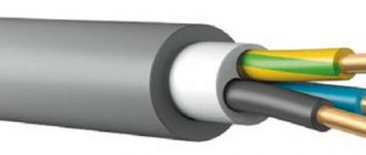
This type of VVG cable has copper conductors, categories 1 and 2 twist classes. Today you can find stranded or polyvinyl chloride conductor models. For example, a three-wire, 4 or 5 cord has a neutral and a ground. Many people often wonder what color ground wire is used in a three-wire wire? Green-yellow polyvinyl chloride plastic is always used to insulate the core.
Wire brand VVG
Cable PV-3
As a rule, a PV-3 cable consists of one core with a twisted copper wire inside. To highlight the outer shell with color, you can use different colors.
Cable brand PV-3
Cable PV-6
The PV-6 brand cord contains a conductive copper core. To create the insulating layer, high quality polyvinyl chloride transparent plastic is used. A distinctive feature of this material is its increased resistance to mechanical stress. If necessary, you can monitor accidental damage to a transparent product. In this case, it is not necessary to adhere to certain standards for the color of the external surface.
You might be interested in this: Checking phasing
Description of conductor of category PV-6
Note! In order to carry out electrical installation work in compliance with all norms and regulations, the conductor is marked with the appropriate color according to international standards.
ESUY cable
A cord of this category can be used to protect the network from short circuits. Power systems with significant currents often resort to using cables of this brand. The main feature of power cable products is resistance to temperature influences. This low-mass conductor is easy to use for electrical work. The voltage rating for ESUY is not specified. This indicator must be set to transport current through the wires. When laying the cable yourself, it is imperative to apply color markings.
Ground wire size
To determine the efficiency, as well as the response speed of the RCD, the most important indicator is calculated - the active resistance of the grounding conductor. By obtaining the correct results, maximum safety from electric shock can be ensured.
Designation of the ground loop on the diagram
Important! The grounding conductor is not subjected to the full load that the phase and neutral conductors must produce. Based on this, the cross-section of the grounding conductor is adopted with reduced parameters.
How to choose the right wire
Before choosing a grounding wire, you need to familiarize yourself with the basic technical and operational characteristics.
Those owners who live in private houses or in old apartments have to ground household equipment with their own hands. It is important to note that most modern apartment buildings have a ready-made grounding system. Before making the right choice, the owner of a residential premises must clarify which system is installed on a particular site. Considering this indicator, it is necessary to select a conductor of the appropriate type.
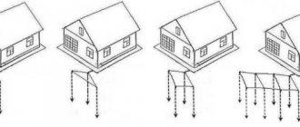
Grounding diagram
When determining the type of installed system, you should take into account the basic rules of electrical devices:
- TN-S - the device can be grounded using a separate wire in the AC system;
- TN-C - “zero” and “ground” cables, they are included in a continuous electrical circuit;
- TT - serves for direct protective grounding, which is installed on electrical equipment;
- IT - is responsible for the operation of the device through increased resistance.
You can also determine the correct conductor cross-section by the type of grounding. Among them, stationary or portable ones stand out. For ordinary household grounding, you can use a stationary option, which allows the use of both stranded and single-wire cables.
In conclusion, it should be noted that grounding the neutral wire plays a very important role not only in creating safe operating conditions for devices, but also for the performance of the entire electrical system. Therefore, such measures for the safe use of electrical installations should not be neglected.
GZSh - copper, steel or aluminum
The basis of the OSUP is the main grounding bus - GZSh. What should it be like and what material should it be made of?
PUE 1.7.119 states that the function of the main switch can be performed by a PE bus inside the switchgear. This is often done.
And if the GZSh is taken outside the panel room, separately from the ASU and mounted on the wall, what rules should be followed when choosing and making calculations?
First, let's decide on the material of manufacture. Paragraph 8 of the circular states that it is recommended that a separately installed main frame be made of steel.
At the same time, the PUE states the opposite, that the GZSh should first of all be copper.
Aluminum is strictly prohibited!
Who to believe in this situation and what to ultimately choose, steel or copper?
The choice is always yours, but experienced professional electricians still prefer copper. This is explained by the fact that energy inspection inspectors, during inspections, are more willing to sign all the papers if there is a copper gas shield.
There are no unnecessary questions or heated debates.
The main grounding bus must connect such elements as:
- neutral protective conductor of the supply line
- conductor connected to a re-grounding device
A metal corner or strip that is buried in the ground on the street or in the basement of a house.
- steel pipes of all communications at the entrance to the building (water supply, sewerage)
- metal building frame elements
- pipes, casings, air ducts of ventilation and air conditioning systems
- working ground conductor
Here is a visual diagram of what should be connected to the main switch by conductors of the potential equalization system.
And now the main question is - what cross-section should the grounding bus be? What does it depend on, where to install it and how to connect it?
