The KG cable is designed for connecting mobile mechanisms to electrical networks at an alternating voltage of 660V with a frequency of up to 400Hz or a constant voltage of 1000V. The flexibility of the cable is ensured by the use of multi-wire conductors and a small pitch of twisting them into the cable.
KG cables are intended for use on land, rivers and lakes in macroclimatic regions with a temperate climate, outdoors and indoors. The cable is resistant to sunlight and repeated bending.
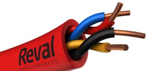
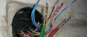
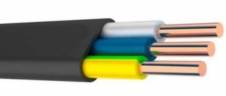
Insulated cores have a distinctive color, solid or in the form of a longitudinal stripe. The insulation of the neutral core is blue; if there is no neutral conductor, blue color is used to color any conductor except the grounding conductor. The grounding conductor has a green-yellow color or is designated by the number 0. The colors of single-core and two-core cables are not standardized.
In the designation of cables with a zero core, the letter “n” is added to the brand; for cables with two and three main cores and one or two auxiliary cores, the letter “c” is added.
conductor
- round made of soft copper wire.
separating layer
- synthetic polyethylene terephthalate film, PET-E grade.
insulation
- special insulating rubber, based on natural and butadiene rubbers.
shell
- hose rubber, type RShT, based on natural and butadiene rubbers.
twisting
- insulated cores are twisted with a twist pitch of no more than 16 twist diameters.
electrical insulation resistance per 1 km length
- at +20°C not less than: 50 mOhm.
number of cores
- 1, 2, 3, 4, 5.
core cross-section, mm²
- 1, 1.5, 2.5, 4, 6, 10, 16, 25, 35, 50, 70, 95, 120, 150, 185, 240, 300, 400.
Additional marking of the KG cable:
T
- tropical cable KG;
HL
- KG cable in cold-resistant design;
type of climatic modification
- U1-U3, HL1-HL3, T.
operating temperature of the KG cable
- - 40°C to + 50°C.
resistance to temperature effects on the core
- up to 75°C.
The tensile force of the cable per 1 mm² of the total cross-section of all cores
is no more than 19.6 N.
The bending radius of the cable
is not less than 8 outer diameters.
service life
- 4 years.
OKP
- 35 4441 01.
GOST
- 22483, 15150-69.
Permissible current loads of the KG cable.
| Number of cores and cross-section, mm² | Current loads, A |
| 1x16 | 189 |
| 1x25 | 240 |
| 1x35 | 298 |
| 1x50 | 362 |
| 1x70 | 437 |
| 1x95 | 522 |
| 1x120 | 632 |
| 2x0.75 | 24 |
| 2x1 | 28 |
| 2x1.5 | 35 |
| 2x4 | 60 |
| 3x1 | 24 |
| 3x1.5 | 31 |
| 3x2.5 | 42 |
| 3x4 | 55 |
| 3x1+1x1 | >24 |
| 3x1.5+1x1.5 | 31 |
| 3x2.5+1x1.5 | 42 |
| 3x4+1x2.5 | 55 |
| 3x6+1x4 | 69 |
| 3x10+1x6 | 88 |
| 3x16+1x6 | 116 |
| 3x25+1x10 | 150 |
| 3x35+1x10 | 180 |
| 3x50+1x16 | 226 |
| 3x70+1x25 | 272 |
| 3x95+1x35 | 327 |
| 3x120+1x50 | 386 |
| 5x2.5 | 42 |
Current loads on cables and wires
The current loads established in the current regulatory documents for the use of cables and wires in electrical networks are indicated in Tables 1 - 11. The specified current values are given for ambient air temperatures of +25 °C and ground temperatures of +15 °C for average installation conditions. If it is necessary to select a specific current load for a specific type of cable or wire and specific installation conditions, you must be guided by the methods specified in the standards and rules.
Table 1. Permissible long-term current for rubber and polyvinyl chloride insulated wires with copper conductors, A
| Conductor cross-section, mm2 | For wires laid | |||||
| open | in one pipe | |||||
| two single-core | three single-core | four single-core | one two-wire | one three-wire | ||
| 0,5 | 11 | — | — | — | — | — |
| 0,75 | 15 | — | — | — | — | — |
| 1 | 17 | 16 | 15 | 14 | 15 | 14 |
| 1,5 | 23 | 19 | 17 | 16 | 18 | 15 |
| 2,5 | 30 | 27 | 25 | 25 | 25 | 21 |
| 4 | 41 | 38 | 35 | 30 | 32 | 27 |
| 6 | 50 | 46 | 42 | 40 | 40 | 34 |
| 10 | 80 | 70 | 60 | 50 | 55 | 50 |
| 16 | 100 | 85 | 80 | 75 | 80 | 70 |
| 25 | 140 | 115 | 100 | 90 | 100 | 85 |
| 35 | 170 | 135 | 125 | 115 | 125 | 100 |
| 50 | 215 | 185 | 170 | 150 | 160 | 135 |
| 70 | 270 | 225 | 210 | 185 | 195 | 175 |
| 95 | 330 | 275 | 255 | 225 | 245 | 215 |
| 120 | 385 | 315 | 290 | 260 | 295 | 250 |
Table 2. Permissible long-term current for wires with rubber and polyvinyl chloride insulation with aluminum conductors, A
| Conductor cross-section, mm2 | For wires laid | |||||
| open | in one pipe | |||||
| two single-core | three single-core | four single-core | one two-wire | one three-wire | ||
| 2,5 | 24 | 20 | 19 | 19 | 19 | 16 |
| 4 | 32 | 28 | 28 | 23 | 25 | 21 |
| 10 | 60 | 50 | 47 | 39 | 42 | 38 |
| 16 | 75 | 60 | 60 | 55 | 60 | 55 |
| 25 | 105 | 85 | 80 | 70 | 75 | 65 |
| 35 | 130 | 100 | 95 | 85 | 95 | 75 |
| 50 | 165 | 140 | 130 | 120 | 125 | 105 |
| 70 | 210 | 175 | 165 | 140 | 150 | 135 |
| 95 | 255 | 215 | 200 | 175 | 190 | 165 |
| 120 | 295 | 245 | 220 | 200 | 230 | 190 |
Table 3. Continuous permissible current for flexible cables and rubber-insulated wires, A
| Conductor cross-section, mm2 | Single-core | Two-core | Three-core |
| 0,5 | — | 12 | — |
| 0,75 | — | 16 | 14 |
| 1,0 | — | 18 | 16 |
| 1,5 | — | 23 | 20 |
| 2,5 | 40 | 33 | 28 |
| 4 | 50 | 43 | 36 |
| 6 | 65 | 55 | 45 |
| 10 | 90 | 75 | 60 |
| 16 | 120 | 95 | 80 |
| 25 | 160 | 125 | 105 |
| 35 | 190 | 150 | 130 |
| 50 | 235 | 185 | 160 |
| 70 | 290 | 235 | 200 |
Table 4. Permissible continuous current for wires with copper conductors with rubber insulation for electrified transport 1, 3 and 4 kV, A
| Conductor cross-section, mm2 | Current | Conductor cross-section, mm2 | Current | Conductor cross-section, mm2 | Current |
| 1 | 20 | 16 | 115 | 120 | 390 |
| 1,5 | 25 | 25 | 150 | 150 | 445 |
| 2,5 | 40 | 35 | 185 | 185 | 505 |
| 4 | 50 | 50 | 230 | 240 | 590 |
| 6 | 65 | 70 | 285 | 300 | 670 |
| 10 | 90 | 95 | 340 | 350 | 745 |
Table 5. Permissible long-term current for cables with copper conductors with impregnated paper insulation for low voltage in a lead sheath, laid in the ground, A
| Conductor cross-section, mm2 | For cables | |||||
| single-core up to 1 kV | two-wire up to 1 kV | three-wire voltage, kV | four-wire up to 1 kV | |||
| doZ | 6 | 10 | ||||
| 6 | — | 80 | 70 | — | — | — |
| 10 | 140 | 105 | 95 | 80 | — | 85 |
| 16 | 175 | 140 | 120 | 105 | 95 | 115 |
| 25 | 235 | 185 | 160 | 135 | 120 | 150 |
| 35 | 285 | 225 | 190 | 160 | 150 | 175 |
| 50 | 360 | 270 | 235 | 200 | 180 | 215 |
| 70 | 440 | 325 | 285 | 245 | 215 | 265 |
| 95 | 520 | 380 | 340 | 295 | 265 | 310 |
| 120 | 595 | 435 | 390 | 340 | 310 | 350 |
| 150 | 675 | 500 | 435 | 390 | 355 | 395 |
| 185 | 755 | — | 490 | 440 | 400 | 450 |
| 240 | 880 | — | 570 | 510 | 460 | — |
| 300 | 1000 | — | — | — | — | — |
| 400 | 1220 | — | — | — | — | — |
| 500 | 1400 | — | — | — | — | — |
| 625 | 1520 | — | — | — | — | — |
| 800 | 1700 | — | — | — | — | — |
Table 6. Permissible long-term current for cables with copper conductors with impregnated paper insulation for low voltage in a lead sheath laid in air, A
| Conductor cross-section, mm2 | For cables | |||||
| single-core up to 1 kV | two-wire up to 1 kV | three-wire voltage, kV | four-wire up to 1 kV | |||
| until 3 | 6 | 10 | ||||
| 6 | — | 55 | 45 | — | — | — |
| 10 | 95 | 75 | 60 | 55 | — | 60 |
| 16 | 120 | 95 | 80 | 65 | 60 | 80 |
| 25 | 160 | 130 | 105 | 90 | 85 | 100 |
| 35 | 200 | 150 | 125 | 110 | 105 | 120 |
| 50 | 245 | 185 | 155 | 145 | 135 | 145 |
| 70 | 305 | 225 | 200 | 175 | 165 | 185 |
| 95 | 360 | 275 | 245 | 215 | 200 | 215 |
| 120 | 415 | 320 | 285 | 250 | 240 | 260 |
| 150 | 470 | 375 | 330 | 290 | 270 | 300 |
| 185 | 525 | — | 375 | 325 | 305 | 340 |
| 240 | 610 | — | 430 | 375 | 350 | — |
| 300 | 720 | — | — | — | — | — |
| 400 | 880 | — | — | — | — | — |
| 500 | 1020 | — | — | — | — | — |
| 625 | 1180 | — | — | — | — | — |
| 800 | 1400 | — | — | — | — | — |
Table 7. Permissible long-term current for cables with aluminum conductors with impregnated paper insulation for low voltage in a lead sheath, laid in the ground, A
| Conductor cross-section, mm2 | For cables | |||||
| single-core up to 1 kV | two-wire up to 1 kV | three-wire voltage, kV | four-wire up to 1 kV | |||
| until 3 | 6 | 10 | ||||
| 6 | — | 60 | 55 | — | — | — |
| 10 | 110 | 80 | 75 | 60 | — | 65 |
| 16 | 135 | 110 | 90 | 80 | 75 | 90 |
| 25 | 180 | 140 | 125 | 105 | 90 | 115 |
| 35 | 220 | 175 | 145 | 125 | 115 | 135 |
| 50 | 275 | 210 | 180 | 155 | 140 | 165 |
| 70 | 340 | 250 | 220 | 190 | 165 | 200 |
| 95 | 400 | 290 | 260 | 225 | 205 | 240 |
| 120 | 460 | 335 | 300 | 260 | 240 | 270 |
| 150 | 520 | 385 | 335 | 300 | 275 | 305 |
| 185 | 580 | — | 380 | 340 | 310 | 345 |
| 240 | 675 | — | 440 | 390 | 355 | — |
| 300 | 770 | — | — | — | — | — |
| 400 | 940 | — | — | — | — | — |
| 500 | 1080 | — | — | — | — | — |
| 625 | 1170 | — | — | — | — | — |
| 800 | 1310 | — | — | — | — | — |
Table 8. Permissible long-term current for cables with aluminum conductors with impregnated paper insulation for low voltage in a lead sheath laid in air, A
| Cross-section of current-carrying conductor, mm2 | For cables | |||||
| single-core up to 1 kV | two-wire up to 1 kV | three-wire voltage, kV | four-wire up to 1 kV | |||
| to W | 6 | 10 | ||||
| 6 | — | 42 | 35 | — | — | — |
| 10 | 75 | 55 | 46 | 42 | — | 45 |
| 16 | 90 | 75 | 60 | 50 | 46 | 60 |
| 25 | 125 | 100 | 80 | 70 | 65 | 75 |
| 35 | 155 | 115 | 95 | 85 | 80 | 95 |
| 50 | 190 | 140 | 120 | 110 | 105 | 110 |
| 70 | 235 | 175 | 155 | 135 | 130 | 140 |
| 95 | 275 | 210 | 190 | 165 | 155 | 165 |
| 120 | 320 | 245 | 220 | 190 | 185 | 200 |
| 150 | 360 | 290 | 255 | 225 | 210 | 230 |
| 185 | 405 | — | 290 | 250 | 235 | 260 |
| 240 | 470 | — | 330 | 290 | 270 | — |
| 300 | 555 | — | — | — | — | — |
| 400 | 675 | — | — | — | — | — |
| 500 | 785 | — | — | — | — | — |
| 625 | 910 | — | — | — | — | — |
| 800 | 1080 | — | — | — | — | — |
Table 9. Permissible long-term current for cables with copper conductors with plastic insulation for voltages up to 3 kV, A
| Nominal core cross-section, mm2 | Single-core | Double-core | Three-core | |||
| on air | in the ground | on air | in the ground | on air | in the ground | |
| 1,5 | 29 | 32 | 24 | 33 | 21 | 28 |
| 2,5 | 40 | 42 | 33 | 44 | 28 | 37 |
| 4 | 53 | 54 | 44 | 56 | 37 | 48 |
| 6 | 67 | 67 | 56 | 71 | 49 | 58 |
| 10 | 91 | 89 | 75 | 94 | 66 | 77 |
| 16 | 121 | 116 | 101 | 123 | 87 | 100 |
| 25 | 160 | 148 | 134 | 157 | 115 | 130 |
| 35 | 197 | 178 | 166 | 190 | 141 | 158 |
| 50 | 247 | 217 | 208 | 230 | 177 | 192 |
| 70 | 318 | 265 | — | — | 226 | 237 |
| 95 | 386 | 314 | — | — | 274 | 280 |
| 120 | 450 | 358 | — | — | 321 | 321 |
| 150 | 521 | 406 | — | — | 370 | 363 |
| 185 | 594 | 455 | — | — | 421 | 406 |
| 240 | 704 | 525 | — | — | 499 | 468 |
Table 10. Permissible continuous current for cables with aluminum conductors with plastic insulation for voltages up to 3 kV, A
| Nominal core cross-section, mm2 | Single-core | Double-core | Three-core | |||
| on air | in the ground | on air | in the ground | on air | in the ground | |
| 2,5 | 30 | 32 | 25 | 33 | 21 | 28 |
| 4 | 40 | 41 | 34 | 43 | 29 | 37 |
| 6 | 51 | 52 | 43 | 54 | 37 | 44 |
| 10 | 69 | 68 | 58 | 72 | 50 | 59 |
| 16 | 93 | 83 | 77 | 94 | 67 | 77 |
| 25 | 122 | 113 | 103 | 120 | 88 | 100 |
| 35 | 151 | 136 | 127 | 145 | 109 | 121 |
| 50 | 189 | 166 | 159 | 176 | 136 | 147 |
| 70 | 233 | 200 | — | — | 167 | 178 |
| 95 | 284 | 237 | — | — | 204 | 212 |
| 120 | 330 | 269 | — | — | 236 | 241 |
| 150 | 380 | 305 | — | — | 273 | 274 |
| 185 | 436 | 343 | — | — | 313 | 308 |
| 240 | 515 | 396 | — | — | 369 | 355 |
Table 11. Permissible continuous current for cables with plastic insulation for a voltage of 6 kV, A
| Nominal core cross-section, mm2 | With aluminum core | With copper core | ||
| on air | in the ground | on air | in the ground | |
| 10 | 50 | 55 | 65 | 70 |
| 16 | 65 | 70 | 85 | 92 |
| 25 | 85 | 90 | 110 | 122 |
| 5 | 105 | 110 | 135 | 147 |
| 50 | 125 | 130 | 165 | 175 |
| 70 | 155 | 160 | 210 | 215 |
| 95 | 190 | 195 | 255 | 260 |
| 120 | 220 | 220 | 300 | 295 |
| 150 | 250 | 250 | 335 | 335 |
| 185 | 290 | 285 | 285 | 380 |
| 240 | 345 | 335 | 460 | 445 |
Main design parameters of the cable - KG
| Number and nominal cross-section of cable cores KG, mm² | Nominal outer diameter of cable KG, mm | Estimated cable weight KG kg/km |
| 1x2.5 | 6,7 | 80 |
| 1x4 | 8,0 | 110 |
| 1x6 | 9,0 | 150 |
| 1x10 | 11,1 | 230 |
| 1x16 | 12,4 | 310 |
| 1x25 | 14,6 | 450 |
| 1x35 | 16,4 | 590 |
| 1x50 | 19,0 | 820 |
| 1x70 | 21,5 | 1090 |
| 1x95 | 24,3 | 1400 |
| 1x120 | 27,7 | 1730 |
| 1x150 | 30,1 | 2070 |
| 1x185 | 32,7 | 2490 |
| 1x240 | 36,8 | 3190 |
| 1x300 | 40,1 | 3910 |
| 1x400 | 43,4 | 4980 |
| 2x0.75 | 8,2 | 90 |
| 2x1.0 | 8,5 | 100 |
| 2x1.5 | 9,4 | 130 |
| 2x2.5 | 11,2 | 190 |
| 2x4 | 13,5 | 280 |
| 2x6 | 15,5 | 380 |
| 2x10 | 21,1 | 680 |
| 2x16 | 23,7 | 920 |
| 2x25 | 28,4 | 1340 |
| 2x35 | 31,2 | 1680 |
| 2x50 | 38,0 | 2450 |
| 2x70 | 42,2 | 3170 |
| 2x95 | 47,4 | 4040 |
| 2x120 | 50,7 | 4800 |
| 2x150 | 57,5 | 6050 |
| 3x0.75 | 8,9 | 110 |
| 3x1.0 | 9,1 | 120 |
| 3x1.5 | 10,1 | 160 |
| 3x2.5 | 12,0 | 230 |
| 3x4 | 14,5 | 350 |
| 3x6 | 16,6 | 460 |
| 3x10 | 22,3 | 840 |
| 3x16 | 25,4 | 1130 |
| 3x25 | 30,4 | 1660 |
| 3x35 | 34,0 | 2150 |
| 3x50 | 39,5 | 2970 |
| 3x70 | 44,7 | 3930 |
| 3x95 | 50,9 | 5100 |
| 3x120 | 54,4 | 6150 |
| 3x150 | 63,0 | 7870 |
| 4x1.0 | 10,1 | 150 |
| 4x1.5 | 11,1 | 200 |
| 4x2.5 | 13,3 | 290 |
| 4x4 | 16,0 | 420 |
| 4x6 | 18,5 | 590 |
| 4x10 | 24,4 | 1000 |
| 4x16 | 27,8 | 1400 |
| 4x25 | 33,7 | 2100 |
| 4x35 | 37,7 | 2730 |
| 4x50 | 43,8 | 3700 |
| 4x70 | 49,7 | 5000 |
| 4x95 | 56,6 | 6500 |
| 4x120 | 62,0 | 8120 |
| 4x150 | 69,2 | 9880 |
| 5x1.0 | 11,1 | 190 |
| 5x1.5 | 12,2 | 240 |
| 5x2.5 | 14,6 | 350 |
| 5x4 | 17,8 | 530 |
| 5x6 | 20,2 | 720 |
| 5x10 | 26,8 | 1250 |
| 5x16 | 30,9 | 1700 |
| 5x25 | 37,4 | 2600 |
| 5x35 | 44,5 | 3440 |
| 5x50 | 50,1 | 4580 |
| 5x70 | 54,9 | 5920 |
| 5x95 | 63,3 | 7820 |
| 5x120 | 67,0 | 9360 |
| 2x0.75+1x0.75 | 8,9 | 110 |
| 2x1+1x1 | 9,1 | 100 |
| 2x1.5+1x1.5 | 10,1 | 160 |
| 2x2.5+1x1.5 | 11,8 | 220 |
| 2x4+1x2.5 | 13,9 | 310 |
| 2x6+1x4 | 16,3 | 440 |
| 2x10+1x6 | 21,0 | 740 |
| 2x16+1x6 | 25,0 | 1070 |
| 2x25+1x10 | 30,0 | 1550 |
| 2x35+1x10 | 32,4 | 1890 |
| 2x50+1x16 | 37,9 | 2600 |
| 2x70+1x25 | 42,7 | 3400 |
| 2x95+1x35 | 48,6 | 4500 |
| 2x120+1x35 | 54,4 | 5880 |
| 2x150+1x50 | 58,1 | 6590 |
| 3x2.5+1x1.5 | 13,2 | 280 |
| 3x4+1x2.5 | 15,5 | 400 |
| 3x6+1x4 | 18,0 | 560 |
| 3x10+1x6 | 23,5 | 950 |
| 3x16+1x6 | 27,6 | 1300 |
| 3x25+1x10 | 33,1 | 1950 |
| 3x35+1x10 | 36,5 | 2400 |
| 3x50+1x16 | 42,4 | 3400 |
| 3x70+1x25 | 47,7 | 4500 |
| 3x95+1x35 | 54,5 | 5890 |
| 3x120+1x35 | 60,9 | 7280 |
| 3x150+1x50 | 64,9 | 8630 |
The KG cable is a multi-core flexible power cable with rubber insulation. The KG marking just stands for: the cable is flexible. The flexibility of this type of cable is ensured on the one hand by a fairly soft rubber insulation, and on the other by internal conductors, which are a multi-core structure of many copper wires. Moreover, depending on the conductivity of the cable, it can also be composite. That is, the cable consists of several thick strands. In the latter case, each twist is separately insulated with a rubber casing. This cable is usually black.
According to its purpose, the KG cable is intended for connecting various electrical appliances and electrical consumers to an electrical network with a voltage of up to 660 V and a frequency of up to 400 Hz. If we consider this type of cable in terms of prevalence, then it is one of the most popular. The fact is that it is most advisable to use it for the manufacture of various types of carriers and extension cords for power tools. Powerful power cables are indispensable for welding machines, both for wires under the holder and ground.
This prevalence is due to the fact that even at low temperatures the rubber sheath does not lose its flexibility, unlike the PVC sheath, as well as the fairly high load that the cable can support.
KG cable design
As mentioned above, the design of this type of cable differs from other types of cables and wires in the presence of a stranded copper conductor and a soft rubber sheath. The conductor is made from soft copper wires by twisting in increments of no more than 16 diameters. The conductor is produced according to GOST 22483-77.
Rubber of the RTISHM brand is used as a material for the sheath of a single cable. If there are several twists in the cable, then the cores are insulated with RTI-1 rubber, and the sheath is made of RShT-2 rubber.
The rubber used is either natural or artificial rubber. The peculiarity of the materials for the sheath and cores is that they are practically not destroyed in the open air and under the influence of sunlight.
To increase the tensile strength of the cable, yarn can be inserted into the conductors. Also, in multi-core products there may be additional insulation between the twists in the form of a film based on PET-E polyethylene terephthalate.
Technical characteristics of the KG cable
Operating temperature: from - 40 to + 50 degrees C
Temperature on the surface of the core: no more than 75 degrees C
Cable bending radius: at least 8 outer diameters
Sunlight resistance: Yes
Moisture resistance: 100%
Service life: at least 4 years
Insulation resistance (1 km length and temperature - 20 degrees C): no less than 50 MOhm
Number of kinks before failure: no less than 30,000
Advantages of the KG cable
We will repeat ourselves a little in relation to the information previously presented in the article, but we believe that a separate coverage of the advantages of the KG cable will be useful.
1. Moisture resistance. This type of cable has a very high resistance to moisture - up to 100%. If the shell is intact, problems will not arise even if it is immersed in water under voltage. This is very convenient when there is a need to work with a power tool, for example in light rain.
2. Increased flexibility. Other similar PVC cables do not have this flexibility. The elasticity of the sheath allows it to be twisted and bent many times without harm to the cable. The rubber shell can withstand a long period of time without cracking over time.
3. Possibility of use in vibration conditions. The cable can be used in various equipment where multiple dynamic loads and vibration are present without problems. In this regard, most power cables of various stationary machines and industrial equipment are equipped with a KG cable.
4. Small voltage loss. This positive characteristic makes it possible to effectively use the KG cable in the form of a welding cable for various welding machines, ranging from small household ones to powerful industrial ones.
Dimensions of cables brand KG
Depending on the cross-section and number of cores of the KG cable, it is produced by industry in coils of various sizes:
from 1 mm2 to 35 mm2 – 150 m; from 35 mm2 to 120 mm2 – 125 m; 150 mm2 – 100 m.
If you buy a KG cable at retail, then they will cut off exactly as much as you need from the coil.
Table of cable diameters KG
(the table shows the core cross-section/cable cross-sectional area - outer diameter in mm)
| One vein | Two wires | Three cores | Four wires | Five veins |
| 2.5 / 6.7 | 0.75 / 8.2 | 0.75 / 8.9 | 1.0 / 10.1 | 1.0 / 11.1 |
| 4 / 8.0 | 1.0 / 8.5 | 1.0 / 9.1 | 1.5 / 11.1 | 1.5 / 12.2 |
| 6 / 9.0 | 1.5 / 9.4 | 1.5 / 10.1 | 2.5 / 13.2 | 2.5 / 14.5 |
| 10 / 11.1 | 2.5 / 11.2 | 2.5 / 12.0 | 4 / 16.0 | 4 / 17.8 |
| 16 / 12.4 | 4 / 13.5 | 4 / 14.5 | 6 / 18.4 | 6 / 20.5 |
| 25 / 14.6 | 6 / 15.5 | 6 / 16.6 | 10 / 24.3 | 10 / 26.8 |
| 35 / 16.4 | 10 / 21.2 | 10 / 22.3 | 16 / 27.8 | 16 / 30.9 |
| 50 / 19.0 | 16 / 23.7 | 16 / 25.4 | 25 / 33.7 | 25 / 37.4 |
| 70 / 21.5 | 25 / 28.4 | 25 / 30.4 | 35 / 37.7 | 35 / 44.5 |
| 95 / 24.3 | 35 / 31.2 | 35 / 34.0 | 50 / 43.8 | 50 / 50.1 |
| 120 / 27.7 | 50 / 38.0 | 50 / 39.5 | 70 /49.7 | 70 / 54.5 |
| 150 / 30.1 | 70 / 42.2 | 70 / 44.7 | 95 /56.6 | 95 / 63.3 |
| 185 / 32.7 | 95 / 47.2 | 95 / 50.6 | 120 / 62.0 | 120 / 67.0 |
| 240 / 35.3 | 120 / 50.7 | 120 / 54.4 | 150 / 69.2 | |
| 300 / 40.1 | 150 / 57.5 | 150 / 63.0 | ||
| 400 / 43.4 |
