How to read car electrical diagrams?
In order to understand the contents of the circuit, you need to know the correspondence between the circuit symbols and the real elements of the device. What functions do these devices perform and how do they interact with each other?
Let's define the terms:
- A circuit element is a component of a circuit that performs a specific function in a product and cannot be divided into parts that have an independent purpose.
- A device is a collection of elements representing a single structure (block, board, etc.).
- Schematic diagram (complete) - a diagram that defines the complete composition of elements and connections between them, and, as a rule, gives a detailed understanding of the principles of operation of the product. Schematic diagrams are used to study the principles of operation of products, as well as for their adjustment, control and repair. They serve as the basis for the development of other design documents, for example, connection diagrams (installation diagrams) and drawings.
- Connection diagram (installation) - a diagram showing the connections of the component parts of the product and defining the wires, harnesses, cables that make these connections, as well as the places of their connections and input (connectors, boards, etc.).
- Layout diagram - a diagram that determines the relative location of the component parts of the product, and, if necessary, also harnesses, wires, cables, etc.
- A harness is a set of wires packaged in a certain way into a single whole.
In the electrical equipment diagrams of cars, the schematic, installation, and layout diagrams are combined into one in a simplified form; the simplification concerns the wiring and layout diagrams. In the diagrams, the devices have a design that to some extent corresponds to their appearance, and they are located according to the diagram in the same way (top view) as in reality physically, with a certain simplification. This combination applies mainly to the circuits of cars of early releases. The circuits of modern cars are designed differently, due to the significant complexity of electrical equipment, the layout is carried out separately.
When reading diagrams, you need to know the fundamental principles:
- All connection wires are color coded, which can consist of one color or two (main and additional). Transverse or longitudinal strokes are applied with additional color.
- Within one harness, wires of the same marking have a galvanic connection (physically connected to each other).
- In the diagrams, the wire at the entrance to the harness is inclined in the direction where it is laid.
- Black color, as a rule, indicates a wire that is connected to the car body (ground).
- The positions of the relay contacts are indicated in the state when no current flows through their winding. According to the initial state, the relay contacts differ - normally closed and normally open.
- Some wires have a digital designation at the point of connection to the device, which allows you to determine where it comes from without tracing the circuit. See table.
According to DIN 72552 (commonly used values):
| Contact | Meaning |
| 15 | Battery positive after the ignition key contacts. |
| 30 | Plus the battery directly. |
| 31 | Minus the battery directly or the housing. |
| 50 | Starter control. |
| 53 | Wiper. |
| 56 | Headlight. |
| 56a | High beam. |
| 56b | Low beam. |
| 58 | Parking lights. |
| 85 | Relay winding (-). |
| 86 | Relay coil (+). |
| 87 | Common relay contact). |
| 87a | Normally closed relay contact. |
| 87b | Normally open relay contact. |
| 88 | Common contact 2 relays. |
| 88a | Normally closed relay contact 2. |
| 88b | Normally open relay contact 2. |
List of the most used symbolic drawings:
Also often with a circuit element there is a symbolic drawing explaining which device this element belongs to.
- Alarm.
- Battery.
- Fan.
- Air damper.
- Oil pressure.
- High beam
- Pad wear sensor.
- Egnition lock.
- Sound signal.
- Turn indicator.
- Outdoor Lighting.
- Heated rear window.
- Windshield washer.
- Rear window washer.
- Headlight washer.
- Interior lighting.
- Windshield cleaner.
- Rear window cleaner.
- Headlight cleaner.
- Cigarette lighter.
- Anti-fog equipment.
- Instrument lighting brightness control.
- Reversing light.
- Glass door lifts
- Coolant temperature.
- Brakes.
- Fuel level and reserve indicator.
- Washer fluid level.
- Coolant level.
Designations of circuit elements.
- Switch.
- Diode.
- Lamp with two filaments.
- Lamp.
- Variable resistor.
- Fuse.
- Resistor.
- Relay.
- Zener diode.
- 1.Off (contacts 1 and 6 are closed);
- 2. Switched on “slowly” (contacts 2 and 4, as well as 5 and 6 are closed);
- 3. “Fast” switched on (contacts 3 and 4 are closed).
» /> Three lever switch. This switch consists of several types of contacts. Non-fixed ones are contacts for turning on the washer, a sound signal and a short-term high beam signal (contacts 2 and 6 are closed), fixed ones are low beam (contacts 4 and 5 are closed), high beam (contacts 2 and 5 are closed), turning on the turn signal and turning on the windshield wiper which has 3 modes:
- 1.Off (contacts 1 and 6 are closed);
- 2. Switched on “slowly” (contacts 2 and 4, as well as 5 and 6 are closed);
- 3. “Fast” switched on (contacts 3 and 4 are closed).
How to read electrical circuit diagrams of foreign cars?
Let's look at an example of reading Nissan car diagrams. To do this, we need to familiarize ourselves with the designation system for elements of electrical equipment on the diagrams. Let's start with the designation of connector contacts. As shown in Fig.1.
Next to the connector picture there is a designation on which side of the connector it is viewed from, the contact side (Terminal Side) (TS) or the harness side (Harness Side) (HS). Please note that the connector outline, where the contacts are viewed from the wire side, is outlined with a line.
Figure 2 and Figure 3 show the designations of the circuit elements, the meaning of which is explained in Table 1.
| Number | Name | Description |
| 1 | Battery | Battery |
| 2 | Fusible link | Fuse installed in the wire |
| 3 | Number fusible link or fuse | Serial number of fused line or fuse |
| 4 | Fuse | Fuse |
| 5 | Current rating | Fuse rating in amperes |
| 6 | Optional splice | The circle indicates that the connection depends on the vehicle version |
| 7 | Connector number | Connector number |
| 8 | Splice | The black circle indicates the connection of conductors |
| 9 | Page crossing | This chain continues on the next page |
| 10 | Option abbreviation | The chain between these marks is present only for all-wheel drive |
| 11 | Relay | Shows internal relay connections |
| 12 | Option description | Shows a variant of the circuit depending on the vehicle |
| 13 | Switch | State of contacts depending on switch position (closed or open) |
| 14 | Circuit | Chain |
| 15 | System branch | Indicates that the connection is going to another system (head lighting) |
| 16 | Shielded line | The line is shielded |
| 17 | Component name | Schematic element name |
| 18 | Ground(GND) | Grounding |
| 19 | Connector | The numbering order of the contacts when viewed from the harness side is indicated. |
| 20 | Connectors | Indicates that the wire has 2 connectors |
| 21 | Wire color | Abbreviation for wire color |
| 22 | Terminal number | Describes the pin number, wire color and signal name |
Table 1.
Color abbreviations
| B=Black | LA = Lavender |
| W=White | OR or O = Orange |
| R = Red | P=Pink |
| G = Green | PU or V (Violet) = Purple |
| L = Blue | GY or GR = Gray |
| Y=Yellow | SB = Sky Blue |
| LG = Light Green | CH = Dark Brown |
| BG = Beige | DG = Dark Green |
| BR = Brown |
In Fig. Figure 4 shows a diagram of normally open and normally closed contacts, this is the state when no current flows through the relay coil.
In Fig.5. The windshield wiper switch is shown in the form of a graphical drawing and two tables. The figure shows a schematic diagram of the internal connections of the switch. The tables describe to us the operation of the switch as a “black box”; it is unknown how the circuit is implemented inside, but at the output the state of the contacts corresponds to those indicated in the table, for the modes:
- OFF - disabled;
- INT - interval;
- LO - low speed;
- HI - high speed;
- WASH - plus turning on the washer.
Connection diagram by wire colors on the radio
High-quality sound makes car trips much more enjoyable, but before you can enjoy your favorite music, you need to connect the radio correctly. This procedure is not very complicated, but due to the fact that each car and radio manufacturer uses its own connectors, some installation difficulties may arise. Connecting the radio according to the color of the wires will come to the rescue.
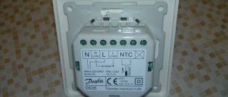
ISO connector
Application of non-standard pressing methods
Considering that purchasing a special tool (the same crimper) requires money, some craftsmen practice a non-standard method of crimping wires. Use a regular electrician's screwdriver with a flat blade of suitable width and thickness.
Using such a screwdriver, the contact rods are pressed, sequentially pressing one at a time into the body of the plug.
The method with a screwdriver is “barbaric”, I must say, but it works. True, the quality of pressing is not always good, resulting in unstable operation of the network cable
Precautionary measures
You need to understand that incorrectly connecting the car radio can lead to unpleasant consequences:
- Breakdown of the radio;
- Deterioration in sound quality;
- Wiring short circuit;
- In rare cases, if you connect the radio to the battery incorrectly, you can quickly discharge it. Sometimes this can cause a fire.
In order not to waste your time, you can use the services of a car repair shop, but you need to be prepared to spend a certain amount that the service will charge for connection. In addition, it is worth considering that the cost of connecting a car radio to a foreign car (for example, Toyota) will be higher. The brand of the car radio is also taken into account. Thus, a Pioneer radio (which is the most common and beloved among motorists) will cost less than a Sony or Kenwood radio.
But if a car enthusiast has a desire to understand the device, the ability to spend a couple of hours and, no less important, the desire to save a decent amount of money, then the rest of the article will describe in detail how to connect a car radio according to the colors of the wires.
Step-by-step instructions for crimping a network cable
Considering that cable connections are used quite often in a variety of conditions, including domestic ones, the question of how to crimp a twisted pair cable onto 8 cores is quite relevant.
Moreover, if not specialists are taken into account, but ordinary users - owners of personal computers.
Let's look at this simple process to make things easier for potential home network circuit builders.
To perform crimping work you will need a special tool:
The first two tools with exotic names are a special press, reminiscent in design of ordinary electrician's pliers and a cutter for removing cable insulation.
In essence, the cutter is an ordinary knife, with the only difference being that it is additionally equipped with recesses for removing the insulating coating.
Car radio device options
All radios are manufactured according to the standards of the company that owns them. The aforementioned Pioneer, Kenwood and Sony are manufactured in accordance with the standards of their companies. However, each of them has a standard ISO adapter. Likewise, every machine has a standard plug for this adapter.
Based on this, one of three situations may arise:
- The first option is ideal. All wires in the car have been removed. Everything is connected according to standards and output to an ISO connector. There will be no difficulties in this case. You just need to connect this connector to the radio.
- The second case is when all the wires are routed correctly, but the connector does not fit. In this case, you can purchase a conductor, of which there are a great many sold in specialized stores, connect the radio through the conductor and enjoy high-quality sound.
- The last option: the wires are not brought out into one connector or there are none at all.
The third option is the most problematic, and therefore it is necessary to consider it further.
What causes danger in an energy-saving lamp?
Many people ask this question and, due to their own safety, continue to ignore these lighting sources, even neglecting the quality that ensures energy savings.
It is known that the internal mechanism of the lamp contains a portion of mercury, and if the integrity of the bulb is damaged, poisoning by chemical vapors can occur. In this regard, people try not to purchase fluorescent light sources. However, there are a number of safety rules when working with this device, which we discussed in previous articles.
Watch a short video on how to connect a fluorescent lamp without a choke:
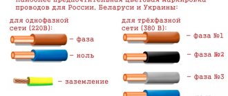
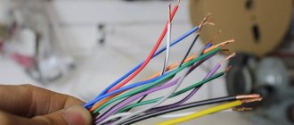
Wire color identification
For the correct connection to work, it is imperative to know the colors of the wires and their designation. The diagram of the radio wires by color is shown in the photo. On all cars and radios (Pioneer, Sony and Kenwood and others) it is customary to use a certain color to indicate the identity of the wire. It is worth noting that the radio wires differ in color and in the presence or absence of a strip. So, all wires with a stripe are a minus, and those without a stripe are a plus.
- Battery negative – black;
- Battery plus – yellow;
- Ignition plus – red;
- Left front speaker – white and white with stripe;
- Right front speaker – gray and gray with stripe;
- Left rear speaker – green and green with stripe;
- Right rear speaker – purple with a purple stripe;
- Antenna – blue;
- Amplifier – blue with a stripe.
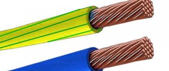
Ground wire color
From 01/01/2011 the color of the grounding (or grounding) conductor can only be yellow-green. This color marking of wires is also observed when drawing up diagrams on which such conductors are signed with the Latin letters PE. The coloring of one of the conductors on cables is not always intended for grounding - usually it is done if there are three, five or more conductors in the cable.
PEN wires with combined “ground” and “zero” deserve special attention. Connections of this type are still often found in old buildings, in which the electrification was carried out according to outdated standards and has not yet been updated. If the cable was laid according to the rules, then blue insulation was used, and yellow-green cambrics were put on the ends and joints. Although, you can also find the color of the grounding (grounding) wire exactly the opposite - yellow-green with blue tips.
Protective grounding is mandatory when laying lines in residential and industrial premises and is regulated by PUE standards and GOST 18714-81. The neutral grounding wire should have as little resistance as possible, the same applies to the grounding loop. If all installation work is carried out correctly, then grounding will be a reliable protector of human life and health in the event of a fault in the power line. As a result, correctly marking cables for grounding is critical, and grounding should not be used at all. In all new houses, wiring is done according to the new rules, and old ones are put in line for replacement.
Connecting a car radio
When connecting the radio, you must strictly follow the diagram. To power the car radio, you need to connect the yellow wire to the battery positive. The black wire goes to ground, this is grounding. The red wire is powered from the ignition switch. Ideally, it should be connected so that it is powered only when the key is in the ACC position.
Since installation difficulties arise precisely in the absence of an ISO adapter, all wires must be stripped and then insulated. Stranded copper wires with silicone insulation are ideal. Once the wiring is complete, they can be combined into a standard adapter, but you can also insulate them with the radio wires. The main thing is that the color of the wires of the radio and the car match each other.
There are several other undesirable options for connecting a car radio to a car. Most motorists, not wanting to bother with connecting the yellow wire to the battery, connect it together with the red wire to the ignition switch. This deprives the radio of more power and does not allow you to get high-quality and powerful sound. The same thing happens when the radio is powered from the cigarette lighter.
It happens that the yellow and red wires are connected to the battery. The advantages of this connection are that the radio is always in standby mode and ready for use. However, this method quickly lands him. Therefore, it is worth thinking about what is more important: the operation of the radio independent of the ignition switch or the long-term operation of the battery?
Connecting speakers
The colors of the radio speaker wires have already been described above. Therefore, in accordance with them, you can safely connect any speakers.
Today, almost all car radios are oriented towards 4 speakers: two in front and two in back. It is worth noting that a powerful audio system has a plus and minus output to each speaker. A weak audio system has only a positive output. Therefore, the minus from the column is displayed on the total mass. To get better sound, it is best to observe the plus and minus contacts.
If poor sound quality occurs after installation, there is a simple and effective way to make the connection correctly. You need to transfer the sound to the front speakers, then transfer the sound to one speaker, for example, the left one. Turn on the music at full volume until wheezing or distortion appears. After that, transfer the sound to the 2 front speakers.
If the sound becomes louder and remains of high quality, then the connection is made correctly. If there is no change in volume, or distortion appears, then you need to check whether the plus and minus are connected correctly.
As you can see, connecting a car radio based on the color of the wires is not difficult and, with a careful approach, will take no more than 2-3 hours.
I mixed up the wires once when I connected the speakers. I don’t know how this happened, most likely just carelessness. As a result, the speakers worked out of phase and jammed each other, causing the sound to deteriorate greatly.
In my car, the left speaker of the radio is very wheezing. Maybe this is due to the fact that I connected the radio itself incorrectly? I'm not sure if it's connected correctly, since this was my first time doing this, and I could have messed something up.
Oh, and a puzzle - these wires. About 6 years ago I bought a Pioneer from a friend with protruding wires. He assured me that I would quickly figure it out and everything would connect fine. I struggled all day, but finally did it. I wouldn’t do such an experiment now.
Tell me, why does my car radio turn off when I turn on the headlights?
The drawdown is big. Try putting a thicker wire on the “+” or installing a more powerful capacitor (larger capacity) in the radio.
I connected the radio for the first time in a 1988 Toyota Corolla. The radio was Pioner DEH-X3500UI. The wires in the car were of the old type, you had to buy an adapter and solder the wires from the car to it, the problem with the car was that the wires were not the same color, not according to the instructions, there were pink, blue and all solid colors. I found an old manual on the Internet and found which wire was responsible for it, soldered everything, connected the radio and everything worked, I had no experience in connecting at all, since it was my first car and the first radio I bought, as they say, the eyes are afraid - the hands do!
How many amperes is the fuse in the FUSIOL radio?
Usually they cost either 10 or 15 amps
Guys, hello everyone. I recently bought an Epic 10 year old. It already had a Chinese radio on it, I want to install the original one, but the chips were cut off by some deb......m, who wouldn't mind if you could send me a diagram of how to connect it. by wire color
Well, why is there no mention in the diagrams and texts of the wire (steering wheel cont...), which is intended for connection to possible steering wheel radio control buttons.
Manual color marking
It is used in cases where during installation it is necessary to use wires with cores of the same color. This also often happens when working in old houses, in which electrical wiring was installed long before the advent of standards.
To avoid confusion during further maintenance of the electrical circuit, experienced electricians used kits that allow them to mark phase wires. This is also allowed by modern rules, because some cables are manufactured without color and letter designations. The place where manual marking is used is regulated by the rules of the PUE, GOST and generally accepted recommendations. It is attached to the ends of the conductor, where it connects to the bus.
Marking of two-core wires
If the cable is already connected to the network, then to search for phase wires, electricians use a special indicator screwdriver - its body has an LED that lights up when the tip of the device touches a phase.
Next, you will need a set of special tubes with a heat-shrinkable effect or insulation tape to mark the phase and zero.
The standards do not require such markings to be made on electrical conductors along their entire length. It is allowed to mark it only at the places of joints and connections of the necessary contacts. Therefore, if there is a need to apply marks on electrical cables without markings, you need to purchase materials in advance to mark them manually.
The number of colors used depends on the scheme used, but there is still a main recommendation - it is advisable to use colors that eliminate the possibility of confusion. Those. Do not use blue, yellow or green marks for phase wires. In a single-phase network, for example, the phase is usually indicated in red.
Marking three-wire wires
If you need to determine phase, zero and grounding in three-wire wires, you can try to do this with a multimeter. The device is set to measure alternating voltage, and then carefully touch the phase with probes (you can also find it with an indicator screwdriver) and the two remaining wires in series. Next, you should remember the indicators and compare them with each other - the phase-zero combination usually shows a higher voltage than phase-ground.
When phase, zero and ground are determined, markings can be applied. According to the rules, a yellow-green colored wire is used for grounding, or rather a core with this color, so it is marked with electrical tape of suitable colors. Zero is marked, respectively, with blue electrical tape, and the phase is any other.
Designation of car radio wires by color
- Orange wire
- Yellow wire
- Yellow and red wire
- Blue wire
- Blue-white wire
- Pink wire
For switching head acoustic equipment, cable bundles covered with insulation of various shades are used. The color coding of the radio wires allows you to correctly connect the player and additional devices. The color range of the protective layer is standardized in accordance with ISO requirements, which ensures compatibility of connectors on radios and car harnesses.
Variety of colors of electrical cable insulation
The color marking of wires is varied and varies greatly for grounding, phase and neutral conductors. To avoid confusion, the PUE requirements regulate what color ground wire to use in the power supply panel, and what colors must be used for zero and phase.
If the installation work was carried out by a highly qualified electrician who knows modern standards for working with electrical wires, you will not have to resort to using an indicator screwdriver or a multimeter. The purpose of each cable core is deciphered by knowing its color designation.
Orange wire
The orange wire is designed to change the intensity of the display backlight together with the lamps of the elements located on the instrument panel. The cable is connected to the positive terminal of the adjustment potentiometer or to the backlight socket of a standard socket or cigarette lighter. On some vehicles, the brightness is automatically reduced when the side lights or headlights are activated. If the user does not plan to use the function, then the cable coming from the radio is twisted and neatly fixed to the harness or plug.
On some radios, the cord is designated ill or lamp; the color of the insulation in this case is arbitrary. It is possible to use 2 separate cables providing negative and positive power. In this case, the negative cord is not connected to the car body.
Letter clues
In electrical wiring diagrams, not only color, but also letter markings are used. The main thing is to remember three designations. This is l, n, pe in electrics. These letter designations are also excellent tips for craftsmen.
Colors and symbols will help you understand the wires
The designation l and n in electrical engineering is applied near the connection terminals. These are the first letters of English words or phrases that indicate the function of a particular wire. These simple symbols will show you how to properly connect the device to the network.
It should be noted that l and n in electrical engineering are universal designations. They are accepted everywhere. This means that there will be no problems with connecting equipment, devices, and devices from foreign manufacturers. And the designations l, n in electrics will tell you which wire needs to be connected to which.
Yellow wire
The yellow wire has an increased cross-section of the core and thicker insulation; it is intended for connecting the head unit with the battery; power is supplied in a constant mode. Thanks to the increased diameter, current is supplied without the risk of overheating the element. To protect the equipment from short circuits in the circuit there is a standard blade-type fuse. The device is placed in a socket on the rear wall of the radio, the rating depends on the power of the built-in amplifier.
When using a separate wire connected to the positive terminal of the battery, it is recommended to additionally protect the circuit. The fuse is mounted in a separate housing at a distance of 300-400 mm from the battery terminal. The cable is laid along standard wiring harnesses; plastic clamps are used to connect the cords into a single trunk. For entry into the cabin, standard holes available in the engine panel of the car are used.
Yellow and red wire
The yellow and red wires are responsible for supplying positive power. The difference between the red wire (which has a larger cross-section) is the method of switching through the ignition switch. Turning the key to the ACC position provides a positive 12V signal to ensure operation of the device. A direct connection of the cable to the positive pole of the battery is allowed, but in this case the radio remains in the active state and contributes to accelerated battery discharge.
The cable with red insulation ensures that the head unit settings are saved when the ignition is turned off. If the connection is incorrect, the player's parameters are reset, which have to be configured again after each start of the car's power unit. To connect to the negative pole of the battery (body), a conductor covered with black insulation is used. The cable is routed to the nearest ground bolt welded to the body. Fastening is done using a clamp, which is tightened with a 6-sided nut.
Wiring insulation colors
Certain regulations also apply to wires used in electrical wiring. Color designation is important for electricians and everyone else who has to work with live networks.
Let's take transformers as an example. As a rule, a three-phase network is used there. Moreover, each phase has its own color designation. It is in relation to three phases that electricians use the abbreviation ZhZK, because this is the easiest way to remember the location of the wires in it.
In a three-phase network, each phase has its own insulation color - yellow, green and red.
The first color is assigned to phase A, the second to phase B, and the third to phase C.
This rule applies to alternating voltage networks with a power of 220 V.
For operation of 380 V networks, a different color designation is used.
Typically the wire markings are as follows:
- A - white;
- B - black;
- C - red.
For the ground wire and the neutral wire, the color designation remains the same - yellow-green and blue.
It is worth remembering that the color of phase-type wires may change and have a different shade, but with regard to wires, zero and ground always comply with the established requirements.
Blue wire
The blue wire provides a control signal to the antenna amplifier or electric drive, which extends the signal receiver pin out of the wing cavity. If the car is not equipped with such equipment, the cable is carefully twisted and insulated. The colors of the wires located on the antenna electric drive unit depend on the vehicle modification.
Blue insulation is also used to protect the cord, which is needed to control an external amplifier. A similar color scheme is used on Sony head units. When the player is activated, a control pulse is sent through the “remote” cable, which ensures the start of operation of the external amplifier and acoustics. After the engine is turned off and the radio stops working, the amplifier is automatically de-energized, ensuring that the vehicle’s battery remains charged.
Blue-white wire
Blue and white insulation colors are used to mark cables used to control low-current external equipment. A positive signal appears on the cable only after the head speaker is turned on. The permissible current transmitted through the cord does not exceed 200 mA. Under increased load, overheating and irreversible destruction of the electronic controllers located inside the player occurs. If the user intends to switch powerful equipment, then it is necessary to introduce a unloading relay into the circuit.
Pink wire
A set of wires for a car radio may contain a cable covered with a pink protective layer. The element is used on head units capable of playing video. Used to switch an external rear view camera, providing signal broadcast. When using this type of equipment, signal compatibility must be ensured, otherwise the display image will be upside down.
To provide power to the camera, a Reverse wire is used, which allows you to enable signal transmission when using reverse gear. The cord is connected to the power supply circuits for the reversing lamps. When using standard parking sensors, it is possible to connect the cable to the controller connector.
An additional harness can be used in the design of the head unit to reduce the sound volume when reverse gear is engaged. The same cable, covered with a yellow-black insulator, is responsible for turning off the broadcast when a phone call arrives. If the car is not equipped with a cell phone connection unit, the cord is not used.
The harness also includes 8 cables intended for connecting rear and front speakers. When using component acoustics, it is necessary to connect the elements to a common channel, while controlling the resistance and power. All negative outputs from the speaker coils must be fed to the appropriate connectors on the amplifier.
It is not allowed to combine the poles into a single line and short circuit the nodes to the car body.
To install the low-frequency speakers, a separate wire is used, laid independently. On some cars, the subwoofer is a standard device, located in the niche for the spare wheel or the internal cavity of its disk. Separate cables are used for switching; the color of the insulation depends on the vehicle model.
On standard radios there is a flat cable designed to transmit information to the display, located in a separate pocket on the instrument panel. The harness consists of a large number of wires covered with white and gray insulation. The protective layer ensures the solidity of the product. The cable is secured with special clamps that ensure reliable contact and protection from moisture.
Some Pioneer head units have an additional cable designed to connect a security system. The cord is connected to the plug, the commutation point is designated Alarm. Using a digital CAN or K-Line bus on a car requires connecting the radio to the circuit. For this purpose, separate cords are used, connected to a common connection connector.
The concept of phase and zero in electrics
Before you begin to consider color marking , you must first understand the concepts of phase and zero in electrical wiring.
- The phase wire (phase) is the part of the wiring through which current is transmitted to the device. It is incorrect to say that if you touch a phase, then with one hundred percent probability this will lead to electric shock. To receive an electric shock, you must become part of the circuit, that is, be a conductor. Therefore, you cannot touch the phase and zero at the same time, and you must also follow safety rules when working: use insulated tools, use dielectric shoes or mats (since the ground can play the role of zero) and special rubberized gloves. The symbolic designation is accepted by the letters A, B, C or L 1, L 2, L 3.
- Zero is a wire through which the electric current returns, but the ions have already changed their charge; its main task is to equalize the phase voltage. The letter designation N is accepted.
- Ground - A non-voltage grounding wire intended to protect against electric shock is designated PE (protective conductor).
Letter designations are used on electrical circuits.
What kind of lighting do you prefer?
Built-in Chandelier
To carry out electrical installation work correctly, it is necessary to strictly follow the rules for connecting live parts; accordingly, all wires in the circuit must be noticeably different from each other. The question becomes reasonable about what color indicates phase and zero in electricity. Below are descriptions of each case separately .
Designations, decoding of contacts and wires of car radios.
Acoustic group:
R = Speaker right. L = Speaker left. FR+, FR- or RF+, RF- = Front speaker - right (plus or minus, respectively). FL+, FL- or LF+, LF- = Front speaker - left (plus or minus, respectively). RR+, RR- = Rear speaker - right (plus or minus, respectively). LR+, LR- or RL+, RL- = Rear speaker - left (plus or minus, respectively). GND SP = Speaker ground.
Power connector for radio:
B+ or BAT or K30 or Bup+ or B/Up or B-UP or MEM +12 = Battery powered (plus)
GND or GROUND or K31 or just a minus = Common wire (Ground), battery minus.
A+ or ACC or KL 15 or SK or S-kont or SAFE or SWA = +12 from the ignition switch.
N/C or n/c or N/A = No contact. (Physically the output is there but not connected anywhere).
ILL or LAMP or sun symbol or 15b or Lume or iLLUM or K1.58b = Panel illumination. +12 volts are supplied to the contact when the side lights are turned on. Some radios have two wires, -iLL+ and iLL-. The negative wire is galvanically isolated from ground.
Ant or ANT+ or AutoAnt or P.ANT = After turning on the radio, +12 volts are supplied from this contact to control the retractable antenna, if one is present, of course.
MUTE or Mut or mu or the image of a crossed out speaker or TEL or TEL MUTE = Input to turn off or mute the sound when receiving a phone call or other actions (for example, reversing).
Other possible contacts in radios:
Power Control = this is the control for turning on the amplifier P.CONT/ANT.CONT = this is the control for the antenna, power is supplied after turning on the radio ILL + and ILL - = these are the wires for adjusting the brightness of the radio backlight Amp = Control contact for turning on the power of the external amplifier DATA IN = Data input DATA OUT = Data output Line Out = Line output REM or REMOTE CONTROL = Control voltage (Amplifier) ACP+, ACP- = Bus lines (Ford) CAN-L = CAN bus line CAN-H = CAN bus line K-BUS = Bidirectional serial bus (K-line) SHIELD = Shielded wire braid connection. AUDIO COM or R COM, L COM = Common wire (ground) of the input or output of preamplifiers CD-IN L+, CD-IN L-, CD-IN R+, CD-IN R- = Balanced line inputs of the audio signal from the SW+ changer B = Power switch +B battery. SEC IN = Second input DIMMER = Changing the brightness of the display ALARM = Connecting alarm contacts for the radio to perform car security functions (PIONEER radios) SDA, SCL, MRQ = Communication buses with the car display. LINE OUT, LINE IN = Line output and input, respectively. D2B+, D2B- = Optical audio link
Marking and color coding of wires
Let's look at the color code for car radio wires:
- Black (indicated by GROUND or GND) is the negative of the battery;
- Red (ACC or A+ marking) is the plus of the ignition switch;
- Yellow (indicated by BAT or B+) is the positive from the battery;
- White with a stripe (marked FL-) is the minus of the front left speaker;
- White without a stripe (indicated by FL+) is a plus of the front left speaker;
- Gray with a stripe (marked FR-) is the minus of the right front speaker;
- Gray without a stripe (indicated by FR+) is a plus for the right front speaker;
- Green with a stripe (marked RL-) is the minus of the left rear speaker;
- Green without a stripe (designation RL+) is a plus for the left rear speaker;
- Purple with a stripe (marked RR-) is the minus of the right rear speaker;
- Purple without a stripe (designation RR+) is a plus for the right rear speaker.
Marking of aluminum cables
APPV 2x6-380 - aluminum wire, PVC coated, flat, has a separator (about the definition a little below), 2 cores with a cross-section of 6 mm. It should be noted that the letter designation is used mainly for high-voltage options.
Color coding helps determine the purpose of the cable. It is used for telephone cords, household appliances (fan, video camera), vehicles (VAZ and others), etc. It is this data that is most important when installing cables or electrical wiring in a new home.
- How to determine the purpose and types of wires by color marking, according to PUE 7:
- Blue – working zero;
- Green is zero protective;
- Black – grounding or “earth”;
- White is the color marking of the phase zero wires.
By the way, different manufacturers may have different types of designations. For example, the phase cable may be white, pink, yellow, orange, gray, red, so be careful when installing or removing the cords. When connecting phase cables to a chandelier or socket, make sure that the colors of the cables being connected match.