Economic Current Density for Busbars
electrical measurements
design
electrical installation
Electrolaboratory
These people trust us
Electrical laboratory » Questions and answers » PUE 7th edition » 1.3.25 - 1.3.32.
SELECTION OF CONDUCTOR SECTION BY ECONOMIC CURRENT DENSITY SELECTION OF CONDUCTOR SECTION BY ECONOMIC CURRENT DENSITY
1.3.25. Conductor cross-sections must be checked for economic current density. Economically feasible section
, mm 2, is determined from the relation
where is the calculated current per hour of maximum power system, A; — normalized value of economic current density, A/mm, for given operating conditions, selected according to table. 1.3.36. The section obtained as a result of the specified calculation is rounded to the nearest standard section. The calculated current is taken for normal operation, i.e. the increase in current in post-emergency and repair modes of the network is not taken into account.
1.3.26. The selection of wire cross-sections for direct and alternating current power lines with voltages of 330 kV and higher, as well as interconnection lines and powerful rigid and flexible conductors operating with a large number of hours of maximum use, is made on the basis of technical and economic calculations.
1.3.27. An increase in the number of lines or circuits beyond what is required under the conditions of reliability of power supply in order to satisfy the economic current density is carried out on the basis of a technical and economic calculation. In this case, in order to avoid increasing the number of lines or circuits, it is allowed to exceed the normalized values given in table two times. 1.3.36.
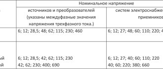
Table 1.3.36. Economic current density
Economic current density, A/mm 2, with the number of hours of maximum load use per year
Bare wires and buses:
Cables with paper and wires with rubber and polyvinyl chloride insulation with conductors:
Cables with rubber and plastic insulation with cores:
Feasibility calculations should take into account all investments in an additional line, including equipment and switchgear chambers at both ends of the lines. The feasibility of increasing the line voltage should also be checked.
These guidelines should also be followed when replacing existing wires with wires of larger cross-section or when laying additional lines to ensure economical current density as the load increases. In these cases, the full cost of all work on dismantling and installing line equipment, including the cost of apparatus and materials, should also be taken into account.
1.3.28. The following are not subject to verification for economic current density: networks of industrial enterprises and structures with voltages up to 1 kV with the number of hours of use of the maximum load of enterprises up to 4000-5000; branches to individual electrical receivers with voltages up to 1 kV, as well as lighting networks of industrial enterprises, residential and public buildings; busbars of electrical installations and busbars within open and closed switchgears of all voltages; conductors going to resistors, starting rheostats, etc.; networks of temporary structures, as well as devices with a service life of 3-5 years.
1.3.29. When using the table. 1.3.36 it is necessary to be guided by the following (see also 1.3.27): 1. At maximum load at night, the economic current density increases by 40%. 2. For insulated conductors with a cross-section of 16 mm or less, the economic current density increases by 40%. 3. For lines of the same section with
branching loads, the economic current density at the beginning of the line can be increased by a factor, and is determined from the expression
Where
— loads of individual sections of the line; — lengths of individual sections of the line; — total length of the line.
4. When choosing conductor cross-sections for power supply
of the same type, mutually redundant electrical receivers (for example, water supply pumps, converting units, etc.), of which they are simultaneously in operation, the economic current density can be increased against the values given in table. 1.3.36, times, where equals:
1.3.30. The cross-section of wires of 35 kV overhead lines in rural areas feeding step-down substations 35/6 - 10 kV with transformers with voltage regulation under load should be selected according to the economic current density. It is recommended to take the design load when choosing wire sections for a 5-year perspective, counting from the year the overhead line was put into operation. For 35 kV overhead lines intended for redundancy in 35 kV networks in rural areas, the minimum long-term permissible current wire cross-sections should be used, based on the provision of power to electricity consumers in post-emergency and repair modes.
1.3.31. The choice of economic cross-sections of overhead wires and cores of cable lines with intermediate power take-offs should be made for each section, based on the corresponding calculated currents of the sections. In this case, for neighboring sections it is allowed to take the same wire cross-section corresponding to the economic cross-section for the longest section, if the difference between the values of the economic cross-section for these sections is within one step on the scale of standard sections. The cross-sections of wires on branches up to 1 km in length are taken to be the same as on the overhead line from which the branch is made. With a longer branch length, the economic cross-section is determined by the design load of this branch.
1.3.32. For power lines with voltage 6-20 kV given in table. 1.3.36 current density values may be used only when they do not cause voltage deviations at electricity receivers beyond permissible limits, taking into account the applied means of voltage regulation and reactive power compensation.
Source
Copper Bus Bandwidth
| Tire section, mm | Direct current, A | Alternating current, A |
| Permissible current copper bus 15×3 | 210 | 210 |
| Permissible current copper bus 20×3 | 275 | 275 |
| Permissible current copper bus 25×3 | 340 | 340 |
| Permissible current copper bus 30×4 | 475 | 475 |
| Permissible current copper bus 40×4 | 625 | 625 |
| Permissible current copper bus 40×5 | 705 | 700 |
| Permissible current copper bus 50×5 | 870 | 860 |
| Permissible current copper bus 50×6 | 960 | 955 |
| Permissible current copper bus 60×6 | 1145 | 1125 |
| Permissible current copper bus 60×8 | 1345 | 1320 |
| Permissible current copper bus 60×10 | 1525 | 1475 |
| Permissible current copper bus 80×6 | 1510 | 1480 |
| Permissible current copper bus 80×8 | 1755 | 1690 |
| Permissible current copper bus 80×10 | 1990 | 1900 |
| Permissible current copper bus 100×6 | 1875 | 1810 |
| Permissible current copper bus 100×8 | 2180 | 2080 |
| Permissible current copper bus 100×10 | 2470 | 2310 |
| Permissible current copper bus 120×8 | 2600 | 2400 |
| Permissible current copper bus 120×10 | 2950 | 2650 |
You can buy electrical copper and aluminum busbars from our company from the warehouse and on order:
Calculation of the theoretical weight of electrical busbars:
At Nevskaya Aluminum Company you can buy aluminum from a warehouse in St. Petersburg or order delivery throughout Russia.
The warehouse of the Nevskaya Aluminum Company is located at 266 Ligovsky Prospect, not far from the Moskovskie Vorota metro station, next to the freight highway - Vitebsky Prospekt, exits to the WHSD and the Ring Road. Loading documents are issued on site.
Source
Economic current density
As the cross-section of the wires decreases, losses during the transmission of electrical energy increase, and as the cross-section increases, the opposite is true - losses decrease, but capital costs for the construction of the electrical network increase.
Thus, the desire to reduce losses leads to an increase in the cross-section of conductors, and the desire to reduce costs leads to its reduction. It turns out to be a vicious circle.
Therefore, from an economic point of view, the best option will be the one in which the sum of the reduced costs is reduced to a minimum, which will correspond to a certain cross-section of the line wires, called the economic cross-section Se.
To determine the economic cross-section of a wire, it is necessary to make complex and time-consuming calculations, as well as compare several options. Therefore, the PUE establishes the value of the economic current density jе for practical calculations:
Where: Im – calculated line current during normal network operation, A.
Recommended economic current densities are shown in the table below, which is based on a return on capital costs of 5 to 8 years:
The duration of maximum load use in hours can be determined from the annual load schedule using the expressions:
Where: Wyear – annual energy consumption, kWh; Рmax – maximum active power, kW;
Average peak load usage (hours per year) for:
- Lighting of internal cities 1500 – 2000;
- Outdoor city lighting 2000 – 2600;
- Industrial enterprises with one work shift 2000 – 3000;
- Industrial enterprises with two work shifts 3000 – 4500;
- Industrial enterprises with three work shifts 4500 – 7000;
When checking or selecting wire cross-sections based on economic current density in accordance with the table above, the calculated current must be determined without taking into account the increase in load during accidents or repairs. The resulting cross-section is rounded to the nearest standard.
The following are not checked for economic current density:
- Electrical networks with voltages up to 1000 V of industrial enterprises and structures and having a Tmax of less than 4000 - 5000 hours per year;
- Branches to individual electrical receivers with voltages up to 1000 V, as well as lighting networks of public and residential buildings, industrial enterprises, tested for voltage loss;
- Networks of temporary structures, as well as installations with a short service life (3-5 years);
- Busbars;
- Wires going to resistances, starting rheostats, and so on;
The economic current density increases by 40% for wires and cables of all cross-sections at maximum load occurring at night, as well as for insulated wires with a cross-section of up to 16 mm 2 inclusive, regardless of the time of maximum.
Source
Advantages of copper busbars
Copper electrical busbars are more expensive than their aluminum counterparts, but have superior technical characteristics. Purchasing copper busbars is beneficial for the following reasons:
- due to high thermal conductivity, the copper busbar will withstand a significantly higher current load compared to aluminum analogues;
- when transmitting energy, losses on the copper busbar are minimized;
- elasticity, resistance to stretching and other mechanical loads without loss of technical characteristics is an important advantage of the product;
- Due to its resistance to changes in temperature and humidity, and the ability to withstand high voltages, a copper busbar is a more economical purchase than its aluminum counterpart.
The objective advantages of the product make it possible to assemble distribution installations with compact dimensions based on copper electrical busbars. The use of such products is becoming increasingly popular and relevant.
Application area
1.3.1. This chapter of the Rules applies to the selection of cross-sections of electrical conductors (bare and insulated wires, cables and buses) for heating, economic current density and corona conditions. If the cross-section of the conductor determined according to these conditions is less than the cross-section required by other conditions (thermal and electrodynamic resistance to short-circuit currents, voltage losses and deviations, mechanical strength, overload protection), then the largest cross-section required by these conditions should be accepted.
Features and application of copper busbars
For the production of electrical busbars, copper strips of the highest degree of purification from impurities are used. Also for the manufacture of products, conductors with a round cross-section intertwined are used. The main application of tires is the production of components for electrical equipment and the manufacture of electrical parts.
The following types of copper busbars are in demand:
- oxygen-free products practically do not contain foreign impurities, withstand temperatures well, are welded and can be soldered;
- tires M1 and M2 contain oxygen, are characterized by high wear resistance and a long service life;
- solid CMT busbars are made from a standard copper alloy and are used for the installation of durable and reliable busbar trunking;
- soft SHMM tires are used in various fields of activity, including metallurgy and aircraft manufacturing.
In addition to the indicated types of material, other types of electrical copper busbars are also in demand on the market. The products are universal in use and do not corrode or oxidize, are well processed, and have design versatility.
Selection of heating conductor cross-sections
1.3.2. Conductors for any purpose must meet the requirements for maximum permissible heating, taking into account not only normal, but also post-emergency conditions, as well as conditions during repairs and possible uneven distribution of currents between lines, bus sections, etc. When checking for heating, a half-hour maximum is accepted current, the largest of the average half-hour currents of a given network element.
1.3.3. For intermittent and short-term operating modes of electrical receivers (with a total cycle duration of up to 10 minutes and an operating period of no more than 4 minutes), the current reduced to the long-term mode should be taken as the calculated current for checking the cross-section of heating conductors. Wherein:
1) for copper conductors with a cross-section of up to 6 mm², and for aluminum conductors up to 10 mm², the current is taken as for installations with long-term operation;
2) for copper conductors with a cross-section of more than 6 mm², and for aluminum conductors with a cross-section of more than 10 mm², the current is determined by multiplying the permissible continuous current by the coefficient
, where Tpk is the duration of the working period expressed in relative units (the duration of switching on in relation to the duration of the cycle).
1.3.4. For a short-term operating mode with a switching duration of no more than 4 minutes and breaks between switching on sufficient to cool the conductors to ambient temperature, the maximum permissible currents should be determined according to the standards of the short-term operating mode (see 1.3.3). When the duration of switching on is more than 4 minutes, as well as during breaks of insufficient duration between switching on, the maximum permissible currents should be determined as for installations with a long operating mode.
1.3.5. For cables with voltages up to 10 kV with impregnated paper insulation that carry less than rated loads, a short-term overload indicated in table may be allowed. 1.3.1.
1.3.6. For the period of liquidation of the post-emergency regime, an overload of up to 10% is allowed for cables with polyethylene insulation, and for cables with polyvinyl chloride insulation up to 15% of the rated load during maximum loads lasting no more than 6 hours per day for 5 days, if the load during the remaining periods of time of these days does not exceed the nominal.
During the period of liquidation of the post-emergency regime, overloads are allowed for 5 days for cables with voltages up to 10 kV with paper insulation. within the limits specified in table. 1.3.2.
Table 1.3.1. Permissible short-term overload for cables with voltages up to 10 kV with impregnated paper insulation
| Preload factor | Type of gasket | Permissible overload in relation to the rated load for, h | ||
| 0,5 | 1,0 | 3,0 | ||
| 0,6 | In the ground | 1,35 | 1,30 | 1,15 |
| In the air | 1,25 | 1,15 | 1,10 | |
| In pipes (in the ground) | 1,20 | 1,0 | 1,0 | |
| 0,8 | In the ground | 1,20 | 1,15 | 1,10 |
| In the air | 1,15 | 1,10 | 1,05 | |
| In pipes (in the ground) | 1,10 | 1,05 | 1,00 | |
Table 1.3.2. Permissible overload for the period of post-emergency liquidation for cables with voltage up to 10 kV with paper insulation
| Preload factor | Type of gasket | Permissible overload in relation to the rated one at maximum duration, h | ||
| 1 | 3 | 6 | ||
| 0,6 | In the ground | 1,5 | 1,35 | 1,25 |
| In the air | 1,35 | 1,25 | 1,25 | |
| In pipes (in the ground) | 1,30 | 1,20 | 1,15 | |
| 0,8 | In the ground | 1,35 | 1,25 | 1,20 |
| In the air | 1,30 | 1,25 | 1,25 | |
| In pipes (in the ground) | 1,20 | 1,15 | 1,10 | |
For cable lines that have been in operation for more than 15 years, overloads should be reduced by 10%.
Overloading cable lines with a voltage of 20-35 kV is not allowed.
1.3.7. The requirements for normal loads and post-accident overloads apply to cables and the connecting and termination couplings and terminations installed on them.
1.3.8. Zero working conductors in a four-wire three-phase current system must have a conductivity of at least 50% of the conductivity of the phase conductors; if necessary, it should be increased to 100% of the conductivity of the phase conductors.
1.3.9. When determining permissible long-term currents for cables, bare and insulated wires and busbars, as well as for rigid and flexible conductors laid in an environment whose temperature differs significantly from that given in 1.3.12-1.3.15 and 1.3.22, coefficients should be applied, given in table. 1.3.3.
Table 1.3.3. Correction factors for currents for cables, bare and insulated wires and busbars depending on ground and air temperatures
| Conditional ambient temperature, °C | Standardized core temperature, °C | Correction factors for currents at the design temperature of the environment, °C | |||||||||||
| -5 and below | +5 | +10 | +15 | +20 | +25 | +30 | +35 | +40 | +45 | +50 | |||
| 15 | 80 | 1,14 | 1,11 | 1,08 | 1,04 | 1,00 | 0,96 | 0,92 | 0,88 | 0,83 | 0,78 | 0,73 | 0,68 |
| 25 | 80 | 1,24 | 1,20 | 1,17 | 1,13 | 1,09 | 1,04 | 1,00 | 0,95 | 0,90 | 0,85 | 0,80 | 0,74 |
| 25 | 70 | 1,29 | 1,24 | 1,20 | 1,15 | 1,11 | 1,05 | 1,00 | 0,94 | 0,88 | 0,81 | 0,74 | 0,67 |
| 15 | 65 | 1,18 | 1,14 | 1,10 | 1,05 | 1,00 | 0,95 | 0,89 | 0,84 | 0,77 | 0,71 | 0,63 | 0,55 |
| 25 | 65 | 1,32 | 1,27 | 1,22 | 1,17 | 1,12 | 1,06 | 1,00 | 0,94 | 0,87 | 0,79 | 0,71 | 0,61 |
| 15 | 60 | 1,20 | 1,15 | 1,12 | 1,06 | 1,00 | 0,94 | 0,88 | 0,82 | 0,75 | 0,67 | 0,57 | 0,47 |
| 25 | 60 | 1,36 | 1,31 | 1,25 | 1,20 | 1,13 | 1,07 | 1,00 | 0,93 | 0,85 | 0,76 | 0,66 | 0,54 |
| 15 | 55 | 1,22 | 1,17 | 1,12 | 1,07 | 1,00 | 0,93 | 0,86 | 0,79 | 0,71 | 0,61 | 0,50 | 0,36 |
| 25 | 55 | 1,41 | 1,35 | 1,29 | 1,23 | 1,15 | 1,08 | 1,00 | 0,91 | 0,82 | 0,71 | 0,58 | 0,41 |
| 15 | 50 | 1,25 | 1,20 | 1,14 | 1,07 | 1,00 | 0,93 | 0,84 | 0,76 | 0,66 | 0,54 | 0,37 | — |
| 25 | 50 | 1,48 | 1,41 | 1,34 | 1,26 | 1,18 | 1,09 | 1,00 | 0,89 | 0,78 | 0,63 | 0,45 | — |
Features of the selection of copper busbars
Visually, an electrical busbar made of copper has the shape of a bar with a rectangular cross-section. You can compare the product to a sheet of metal of increased length and thickness. Standard bar width sizes range from 8 to 250 mm. The minimum and maximum thickness are 1.2 and 80 mm, respectively.
When choosing electrical busbars made of copper alloys, the following criteria are taken into account:
- operating conditions of the product, depending on the maximum current load, products with different ratios of thickness and width are selected;
- Products are supplied in coils and lengths, pressed and drawn. The choice of these parameters is made by the buyer based on his own preferences and installation features;
- The maximum permissible heating temperature of a copper busbar is 70 degrees. When choosing the thickness of the product, this indicator should be taken into account, as well as the ambient temperature. The table of permissible loads shows data based on an air temperature of 25 degrees;
- If you have financial capabilities, it is better to choose busbars with a reserve for current load, in order to avoid product failure due to voltage surges and short circuits.
The operational reliability of copper busbars made in accordance with the requirements of regulatory documents has been confirmed in practice. High-quality material without foreign impurities fully complies with the declared characteristics.
Permissible long-term stress for wires, cords and cables with rubber or plastic insulation
1.3.10. Permissible long-term currents for wires with rubber or polyvinyl chloride insulation, cords with rubber insulation and cables with rubber or plastic insulation in lead, polyvinyl chloride and rubber sheaths are given in Table. 1.3.4-1.3.11. They are accepted for temperatures: cores +65, ambient air +25 and ground + 15°C.
When determining the number of wires laid in one pipe (or cores of a stranded conductor), the neutral working conductor of a four-wire three-phase current system, as well as grounding and neutral protective conductors are not taken into account.
The data contained in the table. 1.3.4 and 1.3.5 should be applied regardless of the number of pipes and the location of their installation (in the air, floors, foundations).
Permissible long-term currents for wires and cables laid in boxes, as well as in trays in bundles, must be accepted: for wires - according to table. 1.3.4 and 1.3.5 as for wires laid in pipes, for cables - according to table. 1.3.6-1.3.8 as for cables laid in the air. If the number of simultaneously loaded wires is more than four, laid in pipes, boxes, and also in trays in bundles, the currents for the wires should be taken according to the table. 1.3.4 and 1.3.5 as for wires laid openly (in the air), with the introduction of reduction factors of 0.68 for 5 and 6; 0.63 for 7-9 and 0.6 for 10-12 conductors.
For secondary circuit wires, reduction factors are not introduced.
Table 1.3.4. Permissible continuous current for wires and cords with rubber and polyvinyl chloride insulation with copper conductors
| Conductor cross-section, mm² | Current, A, for wires laid | |||||
| open | in one pipe | |||||
| two single-core | three single-core | four single-core | one two-wire | one three-wire | ||
| 0,5 | 11 | — | — | — | — | — |
| 0,75 | 15 | — | — | — | — | — |
| 1 | 17 | 16 | 15 | 14 | 15 | 14 |
| 1,2 | 20 | 18 | 16 | 15 | 16 | 14,5 |
| 1,5 | 23 | 19 | 17 | 16 | 18 | 15 |
| 2 | 26 | 24 | 22 | 20 | 23 | 19 |
| 2,5 | 30 | 27 | 25 | 25 | 25 | 21 |
| 3 | 34 | 32 | 28 | 26 | 28 | 24 |
| 4 | 41 | 38 | 35 | 30 | 32 | 27 |
| 5 | 46 | 42 | 39 | 34 | 37 | 31 |
| 6 | 50 | 46 | 42 | 40 | 40 | 34 |
| 8 | 62 | 54 | 51 | 46 | 48 | 43 |
| 10 | 80 | 70 | 60 | 50 | 55 | 50 |
| 16 | 100 | 85 | 80 | 75 | 80 | 70 |
| 25 | 140 | 115 | 100 | 90 | 100 | 85 |
| 35 | 170 | 135 | 125 | 115 | 125 | 100 |
| 50 | 215 | 185 | 170 | 150 | 160 | 135 |
| 70 | 270 | 225 | 210 | 185 | 195 | 175 |
| 95 | 330 | 275 | 255 | 225 | 245 | 215 |
| 120 | 385 | 315 | 290 | 260 | 295 | 250 |
| 150 | 440 | 360 | 330 | — | — | — |
| 185 | 510 | — | — | — | — | — |
| 240 | 605 | — | — | — | — | — |
| 300 | 695 | — | — | — | — | — |
| 400 | 830 | — | — | — | — | — |
Table 1.3.5. Permissible continuous current for rubber and polyvinyl chloride insulated wires with aluminum conductors
| Conductor cross-section, mm² | Current, A, for wires laid | |||||
| open | in one pipe | |||||
| two single-core | three single-core | four single-core | one two-wire | one three-wire | ||
| 2 | 21 | 19 | 18 | 15 | 17 | 14 |
| 2,5 | 24 | 20 | 19 | 19 | 19 | 16 |
| 3 | 27 | 24 | 22 | 21 | 22 | 18 |
| 4 | 32 | 28 | 28 | 23 | 25 | 21 |
| 5 | 36 | 32 | 30 | 27 | 28 | 24 |
| 6 | 39 | 36 | 32 | 30 | 31 | 26 |
| 8 | 46 | 43 | 40 | 37 | 38 | 32 |
| 10 | 60 | 50 | 47 | 39 | 42 | 38 |
| 16 | 75 | 60 | 60 | 55 | 60 | 55 |
| 25 | 105 | 85 | 80 | 70 | 75 | 65 |
| 35 | 130 | 100 | 95 | 85 | 95 | 75 |
| 50 | 165 | 140 | 130 | 120 | 125 | 105 |
| 70 | 210 | 175 | 165 | 140 | 150 | 135 |
| 95 | 255 | 215 | 200 | 175 | 190 | 165 |
| 120 | 295 | 245 | 220 | 200 | 230 | 190 |
| 150 | 340 | 275 | 255 | — | — | — |
| 185 | 390 | — | — | — | — | — |
| 240 | 465 | — | — | — | — | — |
| 300 | 535 | — | — | — | — | — |
| 400 | 645 | — | — | — | — | — |
Table 1.3.6. Permissible continuous current for wires with copper conductors with rubber insulation in metal protective sheaths and cables with copper conductors with rubber insulation in lead, polyvinyl chloride, nayrite or rubber sheaths, armored and unarmored
| Conductor cross-section, mm² | Current *, A, for wires and cables | ||||
| single-core | two-wire | three-wire | |||
| when laying | |||||
| in the air | in the air | in the ground | in the air | in the ground | |
| __________________ | |||||
* Currents apply to wires and cables both with and without a neutral core.
| 1,5 | 23 | 19 | 33 | 19 | 27 |
| 2,5 | 30 | 27 | 44 | 25 | 38 |
| 4 | 41 | 38 | 55 | 35 | 49 |
| 6 | 50 | 50 | 70 | 42 | 60 |
| 10 | 80 | 70 | 105 | 55 | 90 |
| 16 | 100 | 90 | 135 | 75 | 115 |
| 25 | 140 | 115 | 175 | 95 | 150 |
| 35 | 170 | 140 | 210 | 120 | 180 |
| 50 | 215 | 175 | 265 | 145 | 225 |
| 70 | 270 | 215 | 320 | 180 | 275 |
| 95 | 325 | 260 | 385 | 220 | 330 |
| 120 | 385 | 300 | 445 | 260 | 385 |
| 150 | 440 | 350 | 505 | 305 | 435 |
| 185 | 510 | 405 | 570 | 350 | 500 |
| 240 | 605 | — | — | — | — |
Selection of copper bars
The copper electrical busbar is a conductor with low resistance.
Copper electrical busbars are made with a rectangular cross-section. Visually, a copper electrical busbar is similar to a sheet, but thicker. UMMC-OTsM produces copper electrical busbars in a wide range of sizes: thickness 1.2 - 80 mm and width 8 - 250 mm. Tires are produced in pressed and drawn condition, in coils and sections. Cracks, cavities, blisters, transverse tears and dirty technological lubricants are not allowed on the surface of copper busbars. Deviations in cross-sectional shape, mechanical properties, crescent shape do not exceed the values established by regulatory documentation. It is possible to produce non-standard tire shapes. In this case, the shape is specified in the specification and a drawing of the future product must be attached.
The choice of copper busbar depends on the conditions of use. When choosing the current cross-section of copper busbars, take into account the maximum current that will flow through the busbar. Section - the ratio of width and thickness. Based on the value of the maximum current, the busbar cross-section is selected according to PUE and GOST 434-78.
Advantages of copper busbars
Along with copper busbars, aluminum busbars are used in electrical engineering. Aluminum tires are valued for their affordable price and lightness of the metal. However, in the long term, copper bars will be a cost-effective solution.
Copper has high thermal conductivity. With the same cross-section, a copper busbar will withstand a percentage greater load than an aluminum busbar of the same size. The copper busbar minimizes energy loss during transmission. They are highly elastic and resistant to stretching. The copper bus bends easily without losing its technical properties. This allows smaller distribution and power units to be assembled. It is resistant to high and low temperatures and can withstand higher voltages. When choosing between an aluminum busbar and a copper one, preference is given to the latter.
