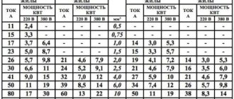
Quite often, electricians are faced with the question of choosing the cross-section of a cable or wire to connect any electrical equipment or an entire facility. As a rule, a person finds a table on the Internet “wire cross-section - permissible current” and chooses based on it.
What can this choice of wire lead to:
- These types of tables do not take into account the length of the cable, or more precisely, its resistance, which can cause a low voltage value at the end of the line, insufficient for normal operation of the connected electrical equipment.
- In the case of equipment with significant starting current values (for example, asynchronous electric motors), the equipment will not be able to enter its operating mode, and other consumers connected to this line will also be affected.
- Economic unreasonableness when choosing a conductor cross-section of a larger value “with a margin”.
- Violation of the Rules for the Construction of Electrical Installations (PUE) and the Rules for the Technical Operation of Consumer Electrical Installations (PTEEP).
- There is no way to check the correctness of the table.
Main steps in determining conductor cross-sections
(block diagram)
When choosing the cross-section of cables and wires, you must proceed from the following conditions:
- Determination of the calculated current (power) for connected electrical equipment.
- Permissible voltage loss (voltage drop across connected electrical equipment). At this stage, the cross-section of the conductors is calculated based on the current load and the length of the line. For example, for electric motors at the moment of voltage supply, a voltage drop is allowed that provides the necessary starting torque, and the operation of other electricity consumers should not be disrupted. This is determined by the electrical energy quality standards GOST 13109-97, PUE, as well as in the technical documentation for a specific type of equipment.
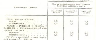
- Heating of conductors of a certain type (permissible continuous current). Selection of conductor cross-sections for heating (paragraph of the same name in the PUE). The amount of current in a conductor of a certain cross-section should not exceed a certain value. This parameter depends on the selected type of cable insulation and the location of its installation.
- Mechanical strength of conductor cores for various types of electrical installations. The minimum permissible cross-section of the conductor is established even if the conductor meets all other parameters (defined in the rules for electrical installations).
- Determination of the cross-section of conductors based on economic current density (paragraph of the same name in the PUE). Economically justified conductor cross-section. (In practice, it is mainly used for calculating large objects)
- Checking the reliability of current protection during a short circuit for the selected cross-section and length of conductors (performed at the stage of calculating the protection devices).
(All GOSTs mentioned in the text at the time of writing this article on May 28, 2018 are valid)
Determination of design values (powers) and current loads of electrical equipment
The task of calculating load power is not as simple a task as it might initially seem. For example, determining the power of such loads as incandescent lamps and electric stoves does not present any difficulties, since this type of load consumes a certain rated power, and this value can be taken as the calculated value.
The situation is more complicated with electric motors, in which the value of the power consumed from the network directly depends on the mechanical torque connected to the mechanism - a metalworking machine, a ventilation unit fan, a circulation pump, etc.
The actual power consumed by the electric motor at a certain point in time may differ significantly from the rated power indicated in the rating data. For example, the actual power consumption of a pump motor may vary depending on: changes in the composition of the pumped medium, pressure in the pipeline, etc. The motor may be either overloaded or underloaded.
Thus, calculating power for a certain group of consumers becomes even more complicated.
The calculated load for current-carrying conductors must be taken as the highest possible load, as the heaviest for wires and cables of the line.
The greatest load should be understood not as a short-term surge (jump), but as the largest average value over a half-hour period of time.
The design load of a group of electrical equipment is determined by the formula:
Kc is the demand coefficient for the highest load (power) mode, taking into account the largest possible number of connected electrical equipment in the group. For electric motors, the demand coefficient must also take into account the value of their load parameter;
Pу is the rated electrical power of the connected group of electrical equipment, equal to the sum of all rated powers of the connected electrical equipment (kW).
The value of the calculated power must be no less than the rated power consumption of the largest of the connected electrical receiver.
The demand coefficient for one electrical receiver (single load) should be taken equal to one.
The demand factors for each type of electrical equipment are different; to determine them, one should be guided by SP 31-110-2003.
Determination of the rated current for three-phase electrical equipment 380 V
For further calculations of the conductor cross-section according to the heating condition, as well as according to the condition of permissible voltage loss, it is necessary to calculate the value of the calculated line current. For three-phase electrical equipment, the value of the calculated current (Ampere) is determined by the formula:
P — Estimated power of all connected electrical equipment, kW; Un — rated supply voltage equal to the phase-to-phase value (linear) Volt; cos f—power factor of a single electrical equipment or the average value of all connected equipment.
Determination of the calculated current for single-phase electrical equipment 220 V
The value of the calculated current (Ampere) for a single-phase electrical receiver or for a group of receivers connected to one phase of a three-phase current network is determined by the formula:
Example No. 1.
It is necessary to determine the calculated current for a carpentry workshop powered from a four-wire line with a rated voltage of 380/220 V. It is planned to install in the workshop:
- 10 asynchronous electric motors, total rated power Py1=18 kW.
- Lighting consisting of incandescent lamps with a total power of Py2=1.3 kW.
- Six household plug sockets (for connecting various office equipment); Pу3= 0.06 kW
According to SP 31-110-2003, the demand coefficient (Kс) for metalworking and woodworking machines in workshops is accepted for the number of working electrical receivers up to 3 Kс = 0.5.
The demand coefficient for calculating the group network of working lighting, distribution and group networks of evacuation and emergency lighting of buildings should be taken Ks = 1
The installed power of the plug socket is taken as 0.06 kW, coefficient Kc = 1.
If there is a mixed connection of general work lighting and a socket network, the calculated load should be added together.
We determine the design load of electric motors:
Lighting and sockets:
We determine the rated load of the sockets:
Total design load:
The calculated current is determined by formula (2):
Selection of fuse links
Fuse links are designed to protect wires from short circuit currents and large overloads.
I When currents pass above the rated value, the fuse link must burn out.
When choosing a fuse link, three conditions are taken into account: 1. Rated current of the fuse link I
VST must be equal to or greater than the calculated current of the protected section of the line, i.e.
I
rise ≥
I
r
For example, if I
p = 30
a
, according to the scale of rated currents of fuse links (Table 19-4), we select the nearest rated current of the insert
I
inst = 35
a
.
2. Rated current of fuse link I
inst must be equal to or greater than the starting current, reduced by 2.5 times for the protected section of the line to which one short-circuited electric motor is connected, i.e.
For example, if; I
start = 200a, then
I
inst ≥ 200/2.5 = 80
a
.
Nearest rated current of fuse link
I
rise = 80
a.
The rated current of a fuse-link for a line to which several squirrel-cage electric motors are connected is calculated according to the formula
I
rise ≥
I
max/2.5 = (
I
start +
I'
r)/2.5
where I
start - the starting current of the engine that has a higher starting current;
I
'р - calculated line current without taking into account the motor that has a higher starting current.
Select a fuse-link with a large current I
inst, found from conditions 1 and 2.
The fuse-link, found by the inrush current, protects the line from unacceptably large short-term inrush currents; In order for the fuse-link to protect the line from long-term overloads, the condition must be met.
3I
d ≥
I
st
3. When choosing fuse links installed in series in the network, each subsequent fuse link, counting from the receiver, should be selected one step higher on the scale of standard fuse link currents. In this case, selective (selective) operation of the fuses is ensured, i.e. the fuse will turn off only the section where the short occurs. The fuse must be installed at the beginning of the section (counting in the direction of energy movement), since only in this case can it protect its section.
Determination of the cross-section of wires or cables based on the permissible voltage loss
The selection of the cross-section of conductors in the cable network must be made according to the permissible voltage loss, which is set in such a way that voltage deviations for all electrical equipment connected to this network do not go beyond the permissible limits.
Rated voltages at the output of power supply systems (according to GOST 21128-83):
According to GOST 13109-97:
- The normally permissible value of steady-state voltage deviation is ±5.
- The maximum permissible value of steady-state voltage deviation is ±10.
Line active and inductive reactance
The active resistance of the line (Ohm/km) is equal to:
When calculating electrical networks based on voltage loss, the active resistance of the wires must always be taken into account. On the contrary, the inductive reactance of the line in some cases can be neglected.
Value of inductive reactance of conductors Calculation of a network based on voltage loss without taking into account the inductive reactance of wires is permissible in the following cases:
- for DC network;
- AC at cosφ = 1
- for networks made with cables or insulated wires laid in pipes on rollers or insulators, if their cross-section does not exceed the values indicated in the table below.
Formulas for calculating the cross-section of conductors for a given voltage loss
Three-phase AC line:
Two-wire AC or DC line:
Where γ is the conductivity of the wire material, m/(Ohm×mm2);
Un — rated network voltage, kV (for a three-phase network Un — phase-to-phase voltage);
∆Uadd – permissible voltage loss in the line, the cross-section of which is determined, %.
F—conductor cross-section, mm2;
∑P∙L=P1∙L1+P2∙L2+…—the sum of the products of the loads flowing along the sections of the line and the length of these sections; loads should be expressed in kilowatts, lengths in meters;
∑Iа∙L= Iа1 ∙L1+ Iа2 ∙L2+…—the sum of the products of the active components of currents passing through the sections and the lengths of the sections;
Currents must be expressed in amperes, lengths in meters.
The active components of the current (A) are determined by multiplying the current values by the power factor values Ia = I∙ cos ɸ.
An example of calculating the minimum cross-section for permissible voltage loss (without taking into account inductive reactance)
Important! It must be remembered that in this calculation we find the value of the minimum cross-section based on the permissible voltage loss across the load; it is also mandatory to check the permissible continuous current (heating of the cable). Table in the PUE (Chapter 1.3)
Example No. 2.
Determine the required cross-section of a two-wire line for spotlights (at the end of the line), using incandescent lamps with a power of 900 W, 3 pieces, total line length 250 m, rated line voltage 220 V, permissible voltage loss UAdd = 5%, aluminum line wires.
Determine the total load:
The sum of the products of the load and the length of the line: ∑P∙L= 2.7 ∙ 250 = 675 kW ∙ m. We substitute the values in formula (7) and determine the cross-sections of the line wires:
Rounding up to the nearest (upwards) standard cross-section (produced by industry), we select the cross-section of the line wires.
Example No. 3.
Determine the cable cross-section for connecting the pump (at the end of the line), using a three-phase asynchronous motor with a mechanical shaft power of 5.5 kW AIR100.
Remember! That the nameplate of the engine does not indicate the electrical power (consumed from the network) but the mechanical power on the shaft (GOST R 52776-2007).
cos ɸ = 0.89, efficiency = 0.848, cable length 130 m, rated line voltage 380 Volts, permissible voltage loss UAdd=5%, line wires are copper.
Thus, for further calculations we need to determine the active component of electrical power:
P2= 5.5/0.848 = 6.485 kW.
We determine the design load of the electric motor (demand coefficient for a single load Kс = 1):
The calculated current is determined by formula (2):
The sum of the products of current and line length: ∑I∙L= 11 ∙ 130 = 1430 A ∙ m. We substitute the values in formula (6) and determine the cross-sections of the line wires:
Rounding up to the nearest (upward) standard cross-section (produced by industry), we determine the cross-section of the line wires to be 2.5 mm2.
And sometimes it is necessary to find out the exact value of the voltage loss in Volts, for this the formula is used:
Let's substitute the values from example No. 3:
And vice versa, if you need to know the percentage of deviation (for example, during practical measurements):
Radio is our element!
VVG cable in PVC insulation
| Current: | A | |
| Power: | kW | |
| cos(φ): | ||
| Section: | ||
| Diameter: | mm | |
| Stock: | + | % |
| = | 1 mm2 | |
| = | 0 % | |
| Imax/Pmax | = | 14A / 6.78KW |
| Stock | = | 40% |
| Lmax(10A, 3.5%) | = | 68m |
| Uout | = | 400 V |
| Machine | = | 3p/C/10A |
| R(1mm 2 .0m) | = | 0 ohm |
| = | 0.75 mm2 | |
| = | 0 % | |
| = | 10A / 4.84KW | |
| Stock | = | 0% |
| Lmax(10A, 5%) | = | 72.9 m |
| U out | = | 400 V |
| Machine | = | 3p/C/10A |
| R(0.75mm 2 .0m) | = | 0 ohm |
| IN | |
| or Umin: | IN |
| m | |
| table 1.3.4, one 3-wire | |
| Imax = Itable * 1 |
| Imax = Itable * 1 |
| tcp = 25°C. |
| = | KG | |
| Route weight | = | KG |
| Cable diameter | = | mm |
| Metalsleeve | : | |
| Corrugated sleeve | : | GR-16/10.7 |