Cable marking - applying color markings, symbols (inscriptions), tags and labels, as well as special electronic markers to the cable. The marking informs about the properties of a given cable, allows you to clearly identify it among other cables or locate its location.
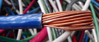
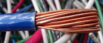
A cable is a structure of one or more conductors (cores) insulated from each other, or optical fibers enclosed in a sheath. In addition to cores and insulation, a cable may contain a screen, core, filler, steel or wire armor, metal sheath, and outer sheath.
Wire - one uninsulated or one or more insulated conductors, on top of which, depending on the installation and operating conditions, there may be a non-metallic sheath, winding or braiding made of fibrous materials or wire.
Wires and cables are marked with letters
The first letter is the core material:
- A - aluminum
- No letter - copper
The second letter is in the wire designation:
- P - wire (PP - flat wire)
- K - control
- M - mounting
- MG - mounting with flexible core
- P(U or Sh) - mounting with flexible core
The third letter is in the designation of wire and cable; core insulation material:
- B or BP - polyvinyl chloride (PVC)
- P - polyethylene
- R - rubber
- N or NR - nayrite (non-flammable rubber)
- F - folded (metal) shell
- K - nylon
- L - varnished
- ME - enameled
- O - polyamide silk braid
- Ш - polyamidone silk insulation
- C - fiberglass
- E - shielded
- G - with flexible core
- T - with support cable
The rubber insulation of the wire can be protected by sheaths: B - polyvinyl chloride, N - nayrite. The letters B and H are placed after the designation of the wire insulation material.
The fourth letter is design features:
- A - asphalted
- B - armored tapes
- G - flexible (wire), without protective cover (power cable)
- K - armored with round wires
- O - braided
- T - for installation in pipes
In addition to letter designations, brands of wires, cables and cords contain digital designations: the first digit is the number of cores, the second digit is the cross-sectional area, the third is the rated voltage of the network. The absence of the first digit means that the cable or wire is single-core. The cross-sectional areas of the cores are standardized. The values of the cross-sectional areas of the wires are selected depending on the current strength, the material of the cores, and laying conditions (cooling).
The designation of cords must include the letter Ш.
Optical fiber color coding
The world has not adopted a single standard on what colors and in what order should be used to encode optical fibers in a cable. However, many countries have their own standard: ANSI/TIA-598 in the USA and many other countries, DIN-VDE 0888 in Germany and parts of Europe and others (Fig. 5):
Rice. 5. Examples of color coding of optical fibers in different countries.
12-color coding is generally accepted due to the fact that in low-light conditions, as often happens somewhere in attics or in the field, the human eye can clearly distinguish only 12 colors. And additional colors are seen as shades of the primary ones and can be easily confused. However, more than 12 fibers, up to 96, can be placed in one optical module (tube). In this case, different encoding schemes are possible. The most popular method is to apply additional strokes (ring marks) to the fiber, which can be used for modules containing up to 48 fibers. The first dozen fibers have a standard color coding, and the subsequent ones are marked with one stroke (ring), two or three next to each other. The second possible way is to use colored winding threads that combine dozens. Thus, the winding thread is also a coding element that determines the order of the dozen. When encoding a large number of fibers with streaks or winding threads, there is a nuance that must be taken into account, especially for ultra-low attenuation fibers: additional microbending losses occur, which slightly increase the attenuation. If the optical module uses no more than 16 fibers, then modern standards allow the use of additional colors instead of applying ring marks.
In Russia there is no single standard defining the order of colors of optical fibers. Different factories use different procedures. This leads to great problems and confusion when installing cables from different manufacturers. All consumers note the inconvenience associated with this. It is necessary to redo the schemes for connecting fibers to each other, to take into account and coordinate different colors with each other.
It would seem that the introduction of the new GOST should solve this problem. GOST contains Appendix B, which defines the order of fiber colors in optical modules according to the ANSI/TIA-598 standard. However, this appendix is for reference only and is therefore optional. Accordingly, confusion and inconvenience associated with different colors will continue. For example, the project uses an ANSI/TIA-598 scheme, but the competition will be won by the manufacturer who uses the DIN VDE 0888 encoding, and this will mean an additional headache for the contractor during installation. Or the use of hard-to-distinguish colors will also lead to difficulties and errors in optical fiber splicing.
Decoding the markings of Russian-made wires and cables
Power cable with PVC (vinyl) and rubber insulation:
- A - (first letter) aluminum core, if absent; copper core by default
- B - (first (in the absence of A) letter) PVC insulation
- B - (second (in the absence of A) letter) PVC sheath
- G - lack of protective cover (“naked”)
- K - armor made of round galvanized steel wires, on top of which a protective layer is applied, if K is at the beginning of the designation, control cable
- KG - flexible cable
- ng - non-flammable
- LS - Low Smoke (low smoke and gas emissions)
- ng-LS - non-flammable, low smoke emission
- LTx - low toxicity of combustion products
- FR - with increased fire resistance (mica-containing tape is usually used as a fire-resistant material)
- FRLS - with reduced smoke emission, with increased fire resistance
- BB - armored cover made of steel tapes
- BN - armored cover made of steel strips, but with a non-flammable protective layer
- PS - insulation or shell made of self-extinguishing, non-flammable polyethylene
- PV - insulation made of vulcanized polyethylene
- C - lead sheath
- Shv - protective layer in the form of an extruded PVC hose (shell)
- Shp - a protective layer in the form of an extruded hose (shell) made of polyethylene
- R - rubber insulation
- NR - rubber insulation and non-flammable rubber sheath
Examples: AVVG, VVG, AVBbShv
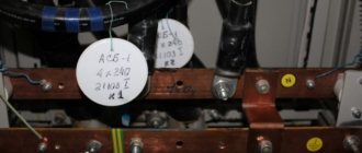
Cable with BPI (paper-belt insulation):
- A - (first letter) aluminum core, if absent; copper core by default
- AB - aluminum armor
- SB - (first or second (after A) letter) lead armor
- l - tape armor
- 2l - double tape armor
- G - lack of protective cover (“naked”)
Examples: ASB, AABL, SBG
Control cable:
- A - (first letter) aluminum core, if absent; copper core by default
- B - (first (in the absence of A) letter) PVC insulation
- B - (second (in the absence of A) letter) PVC sheath
- G - lack of protective cover (“naked”)
- P - polyethylene insulation
- Ps - insulation made of self-extinguishing polyethylene
- F - fluoroplastic insulation
- G - lack of protective cover (“naked”)
- KG - flexible cable
- K - (first or second (after A) letter) - control cable (except KG - flexible cable)
- E - screen
Examples: KVVGe, KVVG, KVBbShng-LS
Telephone cable:
- T - telephone cable
- P - polyethylene insulation
- n - waist insulation; polyamide, polyethylene, polyvinyl chloride or polyethylene terephthalate tapes
- E - screen
- P - polyethylene shell
- Z - hydrophobic filler
- Shp - outer cover made of polyethylene hose
- C - station cable
Examples: TPpp, TPPPePZ, TSVng
Mounting wires:
- M - at the beginning of the designation; installation wire
- G - stranded core, if the letter is missing, then single-wire
- Ш - polyamide silk insulation
- B - polyvinyl chloride insulation
- K - nylon insulation
- L - varnished
- C - fiberglass winding and braiding
- D - double braid
- O - polyamide silk braid
Examples: MGShV, MKSh, MGTFE
Hanging wires:
- A - Aluminum bare wire
- AC - Aluminum-Steel (steel-aluminum) bare wire
- SIP - Self-supporting Insulated Wire
Examples: , SIP
Special designations:
- KSPV - Cables for Data Transmission Systems in PVC sheath
- KPSVV - Fire Alarm Cables with PVC insulation, in PVC sheath
- KPSVEV - Fire Alarm Cables with PVC insulation, with Screen, in PVC sheath
- PNSV - Heating wire, Steel core, PVC sheath
- PV-1, PV-3 - PVC-insulated wire; 1 and 3 are the most applicable core flexibility classes
- PVC - Wire in PVC sheath Connection
- SHVVP - Cord with PVC insulation, in PVC sheath, Flat
- PUNP – Universal Flat Wire
- PUGNP – Universal Flat Flexible Wire
Examples: KSPV, KPSVEV, PVS, ShVVP
Designations in the cable brand, core design characteristics:
- ozh - single-wire conductors (can be either round - OK or sector - OS)
- mn - multi-wire conductors (can be either round or sectored)
- mzh - multi-wire conductors (can be either round or sectored)
- ok - single-wire round conductors
- mk - multi-wire round
- os - single-wire sector
- ms - multi-wire sector
- (N) - zero core, neutral, blue insulation
- (PE) - grounding conductor, yellow-green insulation
Designations in the cable grade in accordance with the requirements of fire codes and regulations:
- ng - cable products that do not spread fire when laid in groups
- ng-LS - cable products that are flame retardant when laid in groups, with reduced smoke and gas emissions
- ng-HF - cable products that do not propagate fire when laid in groups and do not emit corrosive gaseous products during combustion and smoldering
- ng-FRLS - fire-resistant cable products, flame retardant when laid in groups, with reduced smoke and gas emissions
- ng-FRHF - fire-resistant cable products that do not propagate flames when laid in groups and do not emit corrosive gaseous products during combustion and smoldering
- ng-LSLTx - cable products that are flame retardant when laid in groups, with reduced smoke and gas emissions and low toxicity of combustion products
- ng-HFLTx - cable products that do not propagate fire when laid in groups, do not emit corrosive gaseous products during combustion and smoldering, with low toxicity of combustion products
Main variety
Today, cords, cables and wires are used for electrical installation work. Before deciphering the markings, it is necessary to understand what these products are and what their differences are.
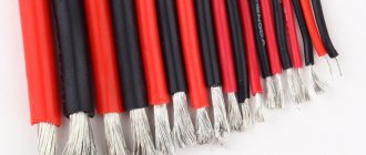
Wires
A wire is an electrical product consisting of one or more wires twisted together, without insulation or insulated. The core sheath is usually light and not made of metal (although wire wrapping is also common).
Such products can be used in electrical installation work (for example, installing electrical wiring in a wooden house), as well as in the manufacture of electric motor windings. Today there are wires with copper and aluminum conductors. The copper version quickly oxidizes in open space and has a high price, but at the same time it is capable of passing through higher current loads. In addition, copper is more elastic, which means it will not break as quickly. Aluminum ones are more fragile and are not connected to copper ones (except perhaps through terminals), but for that they have a low cost. Today, aluminum wiring is used less and less.
It should also be noted that the contacts may be insulated or bare. The latter option is used for power lines. An insulated wire can be protected or unprotected. Protection is provided by another layer of insulation (made of plastic or rubber), which covers the sheath of the cores.
The last classification is carried out depending on the purpose: mounting, power and installation. The mounting wire must be copper; it is used, as a rule, to connect elements of an electrical circuit in a switchboard, as well as to connect circuits in radio equipment. Power (as well as installation) is better known to us, because used outdoors and indoors.
Cables
An electrical cable is a product made up of several wires that are located under one insulating sheath (PVC, rubber, plastic). In addition to this shell, there may be additional protection - an armored shell made of wire or steel tape, which must be indicated in the marking.
There are 5 main types of electrical cables:
- power;
- control;
- For driving;
- for communication;
- radiofrequency.
Let us briefly consider the conditions of use of each product.
Power is used to transmit electricity in power and lighting electrical appliances. There are products of various types and purposes. Power cables are mainly used for external (both overhead and underground) and internal electrical wiring (in residential and non-residential premises). Power cables can have both aluminum and copper conductors. It is recommended to give preference to the latter option. The insulating layer can be PVC, paper, rubber, polyethylene, etc.
The control is used for the operation of electrical devices that transmit an information signal to control any devices. This type can also be with aluminum and copper conductors.
The control cable is a copper electrical conductor with a protective shield. Used in various automation systems. The protective screen serves to remove interference and also protect against mechanical damage.
A communication cable is used to transmit information using currents of various frequencies. Transmission of local communication lines is carried out by low-frequency conductors, and long-distance lines - by high-frequency ones.
RF cable is used in radio engineering devices. The main purpose is the transmission of video and radio signals.
Cords
Cord for household electrical appliances
So we have figured out the main differences between all three types of electrical products. We hope that the information was accessible to you. We also recommend watching the video, which provides this information more clearly:
Main characteristics and differences of conductors
General Differences
All conductors may differ in the following ways:
- Cross section. There are cores with a cross section of 0.35 mm2. up to 240 mm.sq.
- Manufacturing material: copper, aluminum, aluminum-copper (a special composite of two metals).
- Rated voltage (for example, can withstand 220 or 380V).
- Number of cores (single-core or stranded).
- Insulation material (PVC, rubber, paper).
- Protective shell material (rubber, plastic, metal).
Main types of cable markers
A marking tag in accordance with international standards must be installed on open cable routes and power installations. If the wire is laid in structures specially designed for this purpose, then the distance between the markers can be 50-70 m. You cannot do without them in a number of other cases:
- when the route crosses various obstacles that make visual inspection difficult (interfloor ceilings, walls, partitions), then tags are placed on each side of the obstacle passed (for example, on both sides of the wall);
- at points where the direction of the cable line changes;
- in places where input or output from other structures is carried out.
Many manufacturers and electricians prefer cable tags made of plastic, since such material can withstand moisture for a long time without changing its properties.
Form of marking tags
The rules and regulations indicate information on the forms of tags, which were described above:
- triangular - installed in cable lines for control or signaling purposes;
- square – for power lines with voltage up to 1 kV;
- round – over 1 kV.
Label sizes
The most common brands of cable tags are U-134, U-135, U-136 and U-153. Let's compare their sizes and, depending on the data obtained, draw conclusions on possible use in systems:
- U-134 is used to mark power lines with voltages not exceeding 1000 V. The square tag with an area of 55x55 mm is equipped with two 11x3.5 mm grooves for fixing with a cable binder.
- U-135 is suitable for indicating information on electrical circuits with voltages over 1000 V. Round products with a diameter of 55 mm and similar grooves for cable binders.
- U-136 is used for marking signal and control wires. The triangular product has equal sides 62 mm long each. There are two slots for a cable binder of the same size.
- U-153 is used for power lines with voltages up to 1000 V. A square product with a length of 28 mm and a 5 mm hole is attached using a special wire.
Color coding of wires and cables
Generally accepted standards and rules for color marking the insulating sheath of wires allow you to quickly and accurately determine the operating parameters of a cable and understand in which systems and devices it can be used. The color marking regulations are prescribed by PUE and GOST.
It is noteworthy that the designation system will be different for cable networks with alternating current or direct current. Often the cable is made in different colors. Instead of a shell, color marking can be done using heat-shrinkable tubes (cambrics). Another option is colored electrical tape. The choice of color for phase and neutral wires should always be different!
For three-phase alternating power lines, the buses should be marked as follows:
- first phase – yellow;
- the second is green;
- the third is red.
In DC cable runs, color designations are chosen according to the charge, which can be positive or negative. In the first case, a wire with a red braid is selected, in the second, a wire with a blue braid. The system does not support phase and neutral wires, and for the middle wire a light blue conductor is usually used.
For power installations with voltage up to 1 kV and neutral, the following marking is carried out:
- working neutral wire – blue;
- grounding – yellow-green;
- combined zero – yellow-green with blue markers (or blue with yellow-green markers);
- phases - red, black and other colors depending on the quantity.
It is noteworthy that the wiring inside electrical appliances is red, in sockets - brown.
Requirements for types and methods of attaching tags
In addition to the placement of tags, all information about the markings produced on cable lines and communication devices is recorded in a special journal. Such records are regularly updated depending on changes that have occurred in the network structure.
Ley Line Markers
In accordance with GOST, plastic plaques are made in square, round or triangular shapes. They are used in open areas of cable routes and circuit components. The tags have two holes through which the wire or core should be threaded, after which it is securely clamped and fixed in the desired position.
For lines whose voltage does not exceed 1000 V, square tags are used. If the operating voltage is above 1000 V, then round plastic plaques are used. Triangular products are required for control power lines.
Tags for low power circuits
For such purposes, small plates made of polymer materials can be used, which indicate information about the electricity consumption of the circuit subscriber and other data.
Correct calculation
To correctly determine the required area, there are certain techniques. For ease of use, the results of the calculations performed on them are summarized in tables, which are given in various reference books and regulatory documents. Below are some of them, according to which you can choose cable products in plastic or rubber insulation for operation in single-phase and three-phase networks.
Next, we will look at tables with a breakdown of the markings of electrical power copper and aluminum cables and wires for electrical wiring.
Permissible load for copper wires with open (columns 3-5) and hidden (columns 6-8) wiring:
Permissible load for aluminum wires with open (columns 3-5) and hidden (columns 6-8) wiring:
To use the data, it is enough to determine the total power of all consumers that are planned to be connected to the wiring section and select the required diameter or cross-sectional area.
In some cases, the diameter of the wire can be determined “by eye”. Experienced electricians accept the permissible current density as 10 A/sq.mm. This means that a conductor with a cross-section of 1 sq. mm will pass a current of 10 A (at the same time, they talk about a sufficient heating margin). Having obtained the required area, it is multiplied by 4 and divided by the number pi (3.1415) to calculate the diameter.
However, this relationship only works well if the resulting area does not exceed 6 sq. mm. Otherwise, the current loads will be excessive, which can lead to accidents. The selection of the cross-section must be made with a margin
Distinguishing products from each other using different colors
To use cables correctly, it is necessary to distinguish them from each other. To make this easier, the cable is color coded.
To identify cables, brown, black, red, yellow, orange, green, and purple colors are used. And also blue, white, gray, turquoise and pink. This list is established according to GOST.
The blue wire is for the middle or neutral working conductor.
Various color combinations can be used. Green and yellow cannot be used in combinations other than the yellow-green combination, and it is used to indicate the protective neutral conductor.
If the neutral protective conductor is combined with the neutral working conductor, it is designated either along the entire length by a yellow-green combination, and at the ends with light blue, or light blue along the entire length, and at the ends with a combination of yellow and green.
1. Color identification of cores that are insulated with polyvinyl chloride plastic:
– three-core cable: black, blue, brown or a combination of yellow and green, black, blue;
– four-core cable: combination of yellow and green (neutral protective conductor), black, blue, brown.
2. Color identification also exists for three single-core cables, painted black:
3. Color identification according to the functional meaning of the circuits:
– for conductors with power circuits, it is black;
– for conductors having control circuits, signaling and measuring current, which is alternating, it is red;
– for conductors with control, signaling and direct current measurement circuits, it is blue;
– for protective neutral conductors – a combination of yellow and green;
– for conductors that are connected to the neutral working conductor and are not intended for grounding – this is blue.