Let's figure out what the transformation coefficient is. Essentially this is a technical quantity. It's all about the following. In order to account for the electricity consumed by a large facility (such as a residential high-rise building), it becomes necessary to use specialized equipment that reduces the voltage power transmitted to the contacts of a common building meter.
These metering devices are not connected directly to the electrical network of the house, due to the impossibility of connecting high voltage power through a traditional direct-connection meter (they do not work with high currents).
In order to prevent failure of the meter, it is necessary to reduce the power of the supplied voltage.
Transformers are used for these purposes; they are selected based on the required load level.
The transformation ratio of the electricity meter varies depending on the installed equipment. Thus, an electricity meter working in conjunction with a transformer reads a load reduced by 30, 40 or 60 times. Simply put, these numbers represent transformation ratios.
Calculation of indirect connection meter readings
CTs are installed in networks that consume hundreds of kilowatts of electrical energy. The operating principle of such a converter is based on reducing the electric current to a value that allows connecting a standard electric meter through it. For example, a 5 A meter, in a 150 A network, the CT should reduce the indicator by 30 times, that is, the transformation coefficient used in calculating the flow rate is also 30.
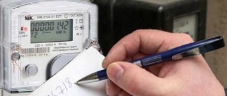
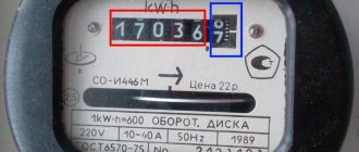
How to read a meter with a current transformer? You just need to count them and subtract the indicator read at the beginning of the billing period.
Then the resulting figure is multiplied by the transformation coefficient specified in the technical documentation or the electricity supplier’s report, calculated independently. This is the answer to the question of how to calculate electricity with current transformers.
Main parameter of the transformer
The main characteristic of any transformer is the transformation ratio. It is defined as the ratio of the number of turns in the primary winding to the number of turns in the secondary winding. In addition, this value can be calculated by dividing the corresponding EMF indicators in the windings.
Formula
In the presence of ideal conditions, when there are no electrical losses, the solution to the question of how to determine the coefficient is carried out using the ratio of the voltages at the terminals of each winding. If the transformer has more than two windings, this value is calculated for each winding in turn.
In step-down transformers, the transformation ratio will be above unity; in step-up devices, this indicator ranges from 0 to 1. In fact, this indicator determines how many times the voltage transformer reduces the supplied voltage. It can be used to determine the correct number of turns. This coefficient is determined on all available phases and on each branch of the network. The data obtained is used for calculations, making it possible to identify wire breaks in the windings and determine the polarity of each of them.
You can determine the real transformation ratio of the transformer current using two voltmeters. In transformers with three windings, measurements are made on at least two pairs of windings with the lowest short-circuit current. If some elements of the transformer and branches are covered with a casing, then determining the coefficient becomes possible only for the terminals of the windings brought out.
In single-phase transformers, to calculate the operating transformation ratio, a special formula is used in which the voltage supplied to the primary circuit is divided by the simultaneously measured voltage in the secondary circuit. To do this, you need to know in advance how each indicator is measured.
It is prohibited to connect voltage to the windings significantly higher or lower than the rated value specified in the transformer passport. This will lead to an increase in measurement errors due to losses of current consumed by the measuring device to which the three-phase transformer is connected. In addition, the measurement accuracy is affected by the no-load current. For most devices, a special table has been developed, which contains fairly accurate data that can be used in calculations.
Measurements should be carried out with voltmeters with an accuracy class of 0.2-0.5. A simpler and faster determination of the coefficient is possible with the help of special universal devices that make it possible to do without the use of extraneous AC voltage sources.
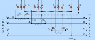
General requirements
Current transformers are equipment that is installed to reduce (convert) the indicator to a level normal for the operation of metering and control mechanisms (meters).
In other words, these devices (manufactured by Mercury, Lenelectro and others) are installed in areas with significant power in cases where direct connection is impossible due to high currents. Direct connection without an appropriate fuse leads to burnout of the magnetic coils and equipment failure.
As a rule, the connection of current transformers is carried out by specialists from special installation and commissioning organizations. Large industries have separate workshops and laboratories.
First of all, an audit of the equipment is carried out - external inspection, testing for operability and maximum power. In addition, the tangent of the internal insulating wire and resistance is measured. Based on the data received, a connection diagram is selected, markings are made, and the required number of holes is drilled.
Electronic or induction
Experts in the field of electrical engineering note that today consumers prefer electronic types of reading devices, since their accuracy class is lower than that of induction devices.
The meter's transformation ratio affects the accuracy of the final readings. On average, induction samples have an accuracy class of 2.5, while electronic samples have an accuracy class of 2.0. This means that the reading error as a result of the operation of an electronic-type electrical reading device is up to 2%, and for an induction one - 2.5%. It is for this reason that electronic equipment is now more often installed, since it allows you to save more by getting more accurate readings. Experts strongly do not recommend installing equipment with an overestimated transformation ratio. In modern electrical engineering, it is customary to use transformers with a static CT, which is guaranteed not to change during operation.
Such electric meters include Mercury-230. Mercury-230 is produced in Russia and is considered one of the best samples for commercial and private use. Mercury-230 can be manufactured for single- and double-tariff plans. Typically, the Mercury-230 model supports a three-phase electrical network. On average, the warranty period for Mercury-230 is 25 years, which is the optimal choice when taking into account quality and price. Mercury-230 fully complies with GOST standards.
Mercury-230 has a good accuracy class and operates stably under significant changes in ambient temperature throughout the entire life of the device. Mercury-230 allows you to accurately measure the current parameters of the electrical network - frequency, power factor, current value of phase current, voltage.
Tariffizer Mercury-230 allows you to simultaneously take into account readings at 4 tariffs in 16 time zones of the day, as well as for four types of days. Mercury-230 can take into account forward active electricity and its total power by phase, the sum of the phase values with determining the direction of the total power vector.
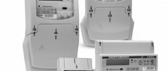
Types of electricity metering devices
Electricity metering devices are multifunctional mechanisms that can reflect the current position of data, store and transmit important information. Today, three different types of counting mechanisms are used.
Mechanical or induction meters
Single-phase induction electricity meters
The classic type of device that is most common. The design consists of two conventional coils. One of them limits the AC voltage data, preventing distortion and receiving electric current. The second converts the flow of alternating voltage.
The main advantages are ease of operation and durability of the devices. The service life of meters of this type is long, and the cost is low. The downside is the dimensions of the mechanism.
Mechanical devices have a large error, which is very noticeable when used in networks with low voltage.
Electronic meters
Modular three-phase electronic electricity meter
The devices have a higher level of accuracy in calculations, but their price is higher. An additional plus is the ability to operate in several modes (for example, morning and night, two- and three-tariff devices).
Electronic meters convert incoming analog readings into special digital encoding, which in turn are converted by a small microcontroller. The received data can be seen on the display. They are trying to install such devices more and more often, replacing outdated mechanical models.
Other advantages are compact size and the possibility of remote control.
Hybrid meters
Hybrid electric meter
They are a middle option between electronic and mechanical type meters. On the one hand, devices are equipped with a digital display for convenience. On the other hand, they use the classic inductive method of obtaining and processing data.
Hybrid devices are rarely installed, preferring analog or electronic mechanisms.
Commercial losses: the main direction of increasing efficiency in the electric power industry
Commercial losses of electricity are considered a difficult value to predict, since they depend on consumers and their desire to deceive the enterprise or the state. The basis of these problems are:
- Seasonal component. The presented concept includes the underpayment of individuals for actually supplied electrical energy. For example, in the Republic of Belarus, there are 2 reasons for the appearance of the “season” - the availability of tariff benefits and payment not on the 1st, but on the 25th.
- Imperfection of metering devices and their incorrect operation. Modern technical means for determining consumed energy have greatly simplified the task for the subscriber service. But electronics or an incorrectly adjusted accounting system can fail, which causes an increase in commercial losses.
- Theft, underestimation of meter readings by commercial organizations. This is a separate topic for conversation, which involves various tricks of individuals and legal entities to reduce electrical energy costs. All this affects the growth of losses.
Useful tips
Electricity meters allow you to see the amount of energy consumed in order to adequately assess consumption and calculate the final payment. Devices differ in accuracy class, power, and degree of permissible error. To obtain accurate data, readings are taken and actual consumption is calculated using a coefficient and a calculator.
For residential buildings in urban areas and villages, small devices are used - single-phase meters (for example, Mercury 230 ART-03 CN, manufactured in Moscow) or multi-tariff devices suitable for a network of 220 Volts or 120 Amperes.
It is important that every new device has a government inspection seal. Without this, the electricity meter readings will not be considered reliable and will not be accepted by regulatory authorities. You can choose a suitable counter and calculate actual indicators yourself or through controllers.
The concept of transformation ratio
To carry out rational control of electricity at large facilities, special equipment is used that reduces the power at the output of the electric meter. These devices are not directly connected to the building's electrical network, which means that it is impossible to directly connect high-voltage voltage to the general electrical network. It follows that in order to minimize the occurrence of malfunctions, it is necessary to reduce the power using transformer equipment. In this case, electricity meters will record a load reduced tens of times. The results obtained in this way will be CT, and in order to determine the real electricity consumption, you should multiply the electric meter readings by the calculated coefficient used.
How to determine the transformation ratio: formula
For indicators exceeding one, a decrease is made, and, conversely, for indicators less than one, a device of an increasing type is used.
Transformation ratios for voltage or current differ.
- U1 and U2 – difference in electrical voltage on the primary and secondary windings;
- N1 and N2 – number of turns of the primary and secondary windings;
- I2 and I1 – indicators of current strength in the primary and secondary windings;
- k – required CT parameters.
As a rule, such parameters of the transformation ratio are necessarily indicated in the accompanying documentation that comes with the equipment. You can also find out this information from the markings on the body of such a device.
A difficult situation is when the CT needs to be calculated independently, according to data obtained empirically. In this case, current is passed through the primary winding of the equipment and a short circuit is made on the secondary winding, after which the amount of electric current passing through the secondary winding is measured.