In this tutorial we will show you how to make your own DIY Arduino Uno board using the ATmega328p microcontroller IC. As a result, you will be able to understand how to make analogues of any boards in the future, plus create your own. Maybe you will even open your own company producing boards and microcontrollers.
Since Arduino is an open source platform, it is quite easy to learn about the innards and details of everything that makes Arduino what it is. So in this tutorial we will look at the Arduino Uno circuit, modify it a little according to our needs, make a PCB for it and solder the necessary components to create the final product.
We will not use any SMD components to create our version of Arduino Uno because not everyone has a soldering station and sometimes it is very difficult to find SMD components. Moreover, our method is cheaper than SMD components in most cases. For those who are just starting to understand electronics, surface mount technology of printed circuit boards is also called TMP (surface mount technology), SMT (surface mount technology) and SMD
-technology (from the English surface mounted device - a device mounted on a surface), and
components
for surface mounting are also called “chip components”.
Firmware and memory Arduino v3 0 CH340G
The standard version of the Arduino Nano board, running on the ATmega328P chip, can be flashed exclusively through a programmer with an SPI interface.
In addition, the AN model is produced, on which the CH340G chip is additionally installed. The advantage of this assembly is that the board can be flashed without connecting an SPI programmer via a USB port. This can be done with the built-in bootloader and USB-COM converter.
If necessary, such a Nano model can also be flashed via the SPI interface.
To download firmware via mini-USB, you will need:
- Connect the board to the PC via USB. The system will detect the device as USB 2.0 SERIAL.
- Download and install the CH340G driver.
As soon as the driver is installed, the system will detect the board correctly and it can be flashed through the programmer. The ON LED on the board will light up and the LED will blink.
Types of memory
ATmega328P supports 3 types of memory:
- Flash. It acts as a permanent storage device.
- RAM.
- EEPROM This memory is also a read-only memory, but it can be reprogrammed.
The microcontroller from Atmel has 32 KB of Flash memory (30 KB free, since 2 KB is occupied by the bootloader), 2 KB of RAM and 1 KB of EEPROM.
Programming Features
Writing code for Arduino Uno is done in the Arduino IDE programming environment. It can be downloaded from the official Arduino Software website. The program interface is completely translated into Russian. After installing the Arduino IDE, you need to select the required platform in the settings.
To do this, you need to perform the following algorithm of actions:
- In the top menu, find the “Tools” menu.
- Open the “Payment” tab.
- From the proposed list you need to select Arduino Uno.
After setting up the programming environment, the user can create a new project, write and compile code. The program must be loaded into the board using the USB port. To do this, you need to connect your PC to the board and click the “Download” button. To save time, you can download additional libraries with ready-made programs for the Arduino IDE.
Example projects with Arduino Nano
It is convenient to implement projects on AN due to the presence of libraries that simplify writing code.
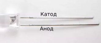
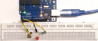
Connecting LEDs to Arduino Nano
You can power the LED diode, for example, using pin 13 through a 220 Ohm limiting resistor. To blink this diode, you should write the following code:
| 1 2 3 4 5 6 7 8 9 10 | void setup(){// initialization of code elements (analogous to int main() in C) pinMode(13, OUTPUT);// declaring pin 13 as an output} void loop(){// infinite loop (analogous to while (1) in C) digitalWrite(13, HIGH);// turn on the LED delay(1000);// ensure blinking with a frequency of 1 Hz digitalWrite(13, LOW);// turn off the LED delay(1000);// ensure blinking with a frequency of 1 Hz} |
void setup() { // initialization of code elements (analogous to int main() in C) pinMode(13, OUTPUT); // declare pin 13 as an output } void loop() { // infinite loop (analogous to while (1) in C) digitalWrite(13, HIGH); // turn on the LED delay(1000); // ensure blinking at a frequency of 1 Hz digitalWrite(13, LOW); // turn off the LED delay(1000); // ensure blinking at a frequency of 1 Hz }
To create a pixel image, where a pixel is 1 diode, the WS2812 address strip is used.
Connecting LCD 1602 to Arduino Nano
The LCD 1602 is a monochrome programmable display. To connect it to the board you need to write the following sketch:
| 1 2 3 4 5 6 7 8 9 10 11 12 | #include
|
#include
- LiquidCrystal lcd(12, 11, 5, 4, 3, 2); void setup(){ lcd.init(); // initializing the screen lcd.backlight(); // activate the backlight lcd.setCursor(0,0); // placing the cursor at the beginning of the first line lcd.print(“text”); // typing text on the first line lcd.setCursor(0,1); // placing the cursor at the beginning of the second line lcd.print(“text”); // typing text on the second line }
Connecting NRF24L01 to Arduino Nano
NRF24L01 is a radio module that is often used to create the Internet of Things. It is installed on the board as follows:
Module pin Pinout boards GND GND VCC 3.3 V C.E. D9 CSN D10 SCK D13 MOSI D11 MISO D12 IRQ Doesn't connect
conclusions
Breadboard development boards are optimal for creating prototypes and digital circuits of low complexity. In their practice, they are often used by both beginners who understand the basics of circuit design and experienced professionals due to the ease of installation and the fairly high quality of connecting working contacts. With the help of such boards, you can quickly and without unnecessary soldering create a prototype, test it, and then assemble a device with a more reliable connection option.
Despite the large number of advantages, breadboards also have disadvantages. They do not allow making a reliable device that can be used in difficult conditions. They are not intended for assembling analog circuits with high sensitivity to resistance values, because The resistance at the point of contact depends on many factors and can vary. The boards must not be connected to a high voltage line. Finally, such boards also cost money - circuit boards with soldering are cheaper.
In any case, for the first projects the Arduino engineer does not have any alternatives. In addition, connecting a breadboard promotes the development of abstract thinking - and this is never superfluous.
Main characteristics
The Arduino Uno board version R3 has the following characteristics:
- Maximum output current of a 5V pin: 0.8 A.
- Quartz processor clock frequency: 16 MHz.
- Number of analog and digital I/O ports: 20.
- Number of ports supporting pulse width modulation: 6.
- Analog-to-digital converter capacity: 10 bits.
- Maximum permissible current from I/O pin: 0.04 A.
- Microcontroller RAM: 2 KB.
- Flash memory: 32 KB (0.5 KB of which is reserved for bootloader).
- Dimensions of the device: 6.9×5.3 cm.
- Allowable input voltage at the power connector: 7-12 V.
- Electrically Erasable Programmable ROM EEPROM: 1 kB.
- Number of built-in LEDs: 1 (located on port 13).
Additional modifications are being developed for the board to improve its technical characteristics. The latest update package was released on March 15, 2022.
Introduction
A robot is a machine that is capable of receiving information from the external environment using a system of sensors, independently processing it and changing the nature of its actions in accordance with this. Most importantly, all these operations must occur without human intervention. It is for this reason that a remote-controlled model, even if it is structurally complex and has an anthropomorphic appearance, cannot be considered a robot, while a simple thermostat or even a fuse in this sense are the simplest robots.
Designing a robotic system is a multifaceted task that requires knowledge of a wide range of scientific and technical issues. The manufacture of electromechanical actuators, for example, the chassis of a robot, will require knowledge of general mechanics and electrical engineering. Creating an action algorithm for a robotic system requires knowledge of computer science, primarily programming skills. To receive information from the external environment, the robot needs various sensors, the use of which will require knowledge of the physical principles of operation of these sensors. Creating the entire system as a whole is impossible without knowledge of electronics. Thus, the process of creating a robotic system will require, in the process of work, obtaining a large amount of information on various natural sciences and physical and mathematical disciplines, which goes far beyond the scope of the school curriculum.
Currently, there are several main ways to begin implementing a robotic system. The first use of ready-made kits for constructing robots, such kits are produced by the famous manufacturer of construction sets for children, Lego. They contain all the necessary components for manufacturing a robot: a microcontroller unit, electric motors, sensors. The undoubted advantage of this path is that constructing a robot based on a ready-made kit can be simple and quick.
All necessary software is included with the robot and has an intuitive interface. However, the cost of such sets is unreasonably high; for a not too large set of sensors and actuators, as well as for a set of standard plastic parts, you will have to pay a very significant amount. Thus, such construction toys are best suited for the younger age group. If the circle is mainly attended by high school students, then it would be more reasonable to allocate funds for equipping the technical creativity circle, to spend on the purchase of measuring instruments, tools, materials and components, and not on the purchase of such sets.
The second way is to create a completely original robotic system using industrially produced microcontrollers, discrete radio elements, electric motors, etc. By acting in this way, you can get a device that is not inferior in its functionality to a device manufactured in a factory. True, this will require a thorough knowledge of the selected microcontroller and the assembler specific to this microcontroller. And this is not to mention the presence of at least a minimal machine park, the maintenance of which requires specialists with specialized education. In the context of a technical creativity circle, this path is hardly feasible, at least if the circle is just starting to study issues of robotics.
In addition to the above options, there is a third way - using the Arduino computing platform. It is based on a special board with a microcontroller, as well as a specialized Wiring development environment created based on the C++ language.
The software is completely free and can be downloaded from the manufacturer’s official website. There are versions for all major operating systems Windows, Linux, MacOS. When developing the software part of the complex in this environment, many routine operations are hidden from us, which simplifies development. However, on the other hand, the program is written in a high-level language, so when compiled into machine codes, the resulting program will not be optimal in size and execution time.
In other words, a program written in Assembly language will take up less space and run faster. If an educational robot or consumer electronic device is being designed, in most cases this is not so important; in fact, if the alarm reacts to a broken window not after 0.1 s, but after 0.2 s, this will not fundamentally change anything. However, in critical cases, the amount of memory required for a program, and especially the speed of operation, can become critical, so among specialists in the development of hardware and software systems, the attitude towards this platform is at least ambiguous. However, no one would even think of using Arduino in life support systems, industrial, aviation and space systems, and amateurs are extremely rarely faced with the need to create such systems.
In the amateur environment, Arduino has actually become a standard. The use of complete Arduino functional blocks greatly simplifies and therefore speeds up the production of devices. It is important to us how this or that unit reacts to certain signals and influences, but not fundamentally its internal structure. In fact, Arduino nodes are, from the point of view of cybernetics, “black boxes”. However, there is an opinion that Arduino is a kind of amateur radio fast food, the use of which is unworthy of a real radio amateur.
It can be argued that almost any electronic device is assembled from factory-made parts. Ultimately, what is any microcircuit if not a “black box”? What is important to us is how the microcircuit responds to a particular electronic signal, while its internal structure is usually unknown, or we only know it approximately. If you deny the use of ready-made components, you can come to the conclusion that a real radio amateur must make radio tubes himself (I can’t imagine how to make a transistor under artisanal conditions) or, in general, first master the extraction of copper ore, metal smelting and wire drawing.
In general, Arduino allows, on the one hand, to learn the basics of working with microcontrollers and constructing complete devices, on the other hand, the amount of initial knowledge required to get started is not too large and is quite accessible to a student.
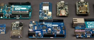
What is Arduino?
Arduino is a family of electronic platforms designed for learning electronics design.
Arduino NANO is a compact microelectronic prototyping platform designed for use with a development board. The functionality of the device is in many ways similar to Arduino UNO and differs from it only in the size of the board and the absence of a separate connector for power.
The basis of the Arduino Nano is a microcontroller based on ATmega328, a logical chip for data processing with a clock frequency of 16 MHz, which has 8 analog and 14 general-purpose digital pins on board, as well as all the necessary interfaces: I2C, SPI and UART.
Installing drivers
On Windows, the drivers will be installed automatically when you connect the board if you used the installer. If you downloaded and extracted the Zip archive or for some reason the board is not recognized correctly, follow the procedure below.
Pin description/Arduino Nano pinout
Each of the Nano's 14 digital pins can be configured as an input or output using the pinMode(), digitalWrite(), and digitalRead() functions. The pins operate at 5 V. Each pin has a 20-50 kOhm load resistor and can carry up to 40 mA. Some pins have special functions:
- Serial bus: 0 (RX) and 1 (TX). The pins are used to receive (RX) and transmit (TX) TTL data. These pins are connected to the corresponding pins of the FTDI USB-to-TTL serial bus chip.
- External Interrupt: 2 and 3. These pins can be configured to trigger an interrupt on either a low value, a rising or falling edge, or a value change. See the attachInterrupt() function for details.
- PWM: 3, 5, 6, 9, 10, and 11. Either pin provides 8-bit PWM using the analogWrite() function.
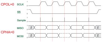
- SPI: 10 (SS), 11 (MOSI), 12 (MISO), 13 (SCK). These pins provide SPI communication, which, although supported by the hardware, is not included in the Arduino language.
- LED: 13. Built-in LED connected to digital pin 13. If the pin value is high, the LED is lit.
The Nano platform has 8 analog inputs, each with a resolution of 10 bits (i.e., can take 1024 different values). By default, the pins have a measurement range of up to 5 V relative to ground, however it is possible to change the upper limit using the analogReference() function. Some pins have additional functions:
- I2C: A4 (SDA) and A5 (SCL). The pins provide I2C (TWI) communication. The Wire library is used for creation.
Additional pair of platform pins:
- AREF. Reference voltage for analog inputs. Used with the analogReference() function.
- Reset. A low signal on the pin resets the microcontroller. Typically used to connect a reset button on an expansion board, which blocks access to the button on the Arduino board itself.
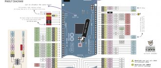
Arduino Nano board pinout
The figure shows the numbers and pin assignments of the Arduino Nano (view from the side on which the Atmega328 microcontroller is located):
Color interpretation:
– gray color – physical pin of the Atmega328 microcontroller;
– light gray color (PD0, PD1, etc.) – microcontroller port number, which is accessible from assembler programs;
– green color (ADC0, etc.) – numbers of analogue pins;
– blue color – pins of UART and SPI ports.
Purpose and pin designations:
USB is a USB port designed to connect the Arduino to a computer via a USB cable (a Mini-B USB connector is required).
VIN – power can be supplied here from an external 7-12 V power source (the power supply must be purchased separately). The voltage will be supplied to the stabilizer and dropped to 5 V. Therefore, it is optimal to supply about 9 V to this pin.
5V – through this pin you can also power the board from a 5 volt power source, but the voltage must be more or less stable, since it is supplied directly to the microcontroller (the stabilizer is not involved), and therefore high voltage can kill the main microcontroller.
3.3V – a voltage of 3.3 V will hang on this pin, which is generated from the board’s internal stabilizer. This pin is needed to connect some external devices that require 3.3 V to operate - usually these are all kinds of LCD displays. However, the maximum output current should not exceed 50 mA.
GND – ground (Ground Pin).
AREF – reference voltage for analog inputs. Used as needed (configured using analogReference()).
IOREF – allows you to find out the operating voltage of the microcontroller. Rarely used. It is completely absent on Chinese boards.
Reset – resets the microcontroller, apply a low level to this input.
SDA, SCL – TWI/I2C interface pins.
D0…D13 – digital inputs/outputs. There is a built-in LED hanging on pin D13, which lights up if the HIGH level is applied to pin D13.
0 (RX), 1 (TX) – pins of the UART port (Serial port).
A1…A5 – analog inputs (can also be used as digital).
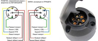
Appearance of the Arduino Nano board with labeled pins:
Here:
RX+TX LEDs - LEDs blink when data is transmitted through the Serial UART serial port (RX and TX pins).
Reset Button – button to restart the microcontroller;
(see other designations above)
FTDI USB chip – FTDI FT323RL chip, which is used to connect the Arduino to a computer via a USB cable. From the Arduino side, this is a serial interface. This interface will be available on the computer as a virtual COM port (drivers for the FTDI chip must be installed - usually included in the Arduino IDE).
Schematically it looks like this:
Pin number, name, pin type and description:
GPIO
Let's start with the pins, which are the most numerous, these are GPIO, from English. General Purpose Input-Output, general purpose inputs and outputs, on the board they are labeled as D0–D13 and A0–A5. According to the pinout picture, they are called PD*, PB* and PC*, (instead of an asterisk - a number) are marked in dark beige. Why are they “officially” called PD/PB/PC? Because the pins are combined into several ports (no more than 8), in the Nano example there are three ports: D, B and C, respectively, the pins are labeled like this: PD3 – Port D 3 – the third output of port D. These are digital pins capable output a logic signal (0 or VCC) and read the same logic signal. VCC is the supply voltage of the microcontroller, in normal use of a regular Arduino board it is 5 Volts, accordingly this is 5 volt logic: 0V is a low level signal (LOW), 5V is a high level signal (HIGH). The supply voltage of the microcontroller plays a very important role, we will talk about this later. GPIOs have several operating modes: input (INPUT), output (OUTPUT) and input with a pull-up to the power supply by a 20 kOhm resistor built into the MK (INPUT_PULLUP). We'll talk more about modes in a separate lesson.
All GPIO pins in input mode can accept a signal with a voltage from 0 to 5 volts (actually up to 5.5 volts, according to the microcontroller datasheet). Negative voltage or voltage exceeding 5.5 Volts will lead to failure of the pin or even the MK itself. A voltage of 0-2.5 volts is considered low level (LOW), 2.5-5.5 is considered high level (HIGH). If the GPIO is not connected anywhere, i.e. “hangs in the air”, it receives random voltage arising from interference from the network (220V wires in the walls) and electromagnetic waves at different frequencies that permeate the modern world.
GPIO in output mode (OUTPUT) are transistor outputs of the microcontroller and can output voltage 0 or VCC (MCU supply voltage). It is worth noting that the microcontroller is a logical, not a power device; its outputs are designed to send signals to other pieces of hardware, and not to directly power them. The maximum current that can be removed from the GPIO output of the Arduino is 40 mA. If you try to remove more, the pin will fail (the output transistor will burn out and that’s it). What is 40 mA? A regular 5mm single-color LED consumes 20 mA, and this is practically the only thing that can be powered directly from the Arduino. Also, do not forget about the maximum current from all pins, it is limited to 200 mA, that is, no more than 10 LEDs can be powered from the board at full brightness...
Interfaces
Most GPIOs have additional capabilities, since pins from other microcontroller systems are connected to them, you are already familiar with them from the previous lesson:
- ADC (ADC, analog-to-digital converter) – green ADC* signatures on the pinout
- UART (communication interface) – blue TXD and RXD on pinout
- Timer outputs, also known as PWM pins, are light purple OC*A and OC*B, where * is the timer number
- SPI (communication interface) – blue SS, MOSI, MISO, SCK
- I2C (communication interface) – blue SDA and SCL
- INT (hardware interrupts) – pink INT0 and INT1, as well as PCINT* – PinChangeInterrupt
ADC
ADC pins (with ADC) are marked on the board with the letter A. Yes, pins A6 and A7 on the Nano board have only an ADC input and are not GPIO pins! ADC is an analog-to-digital converter that allows you to measure voltage from 0 to VCC (MK supply voltage) or reference voltage. On most Arduino boards, the ADC capacity is 10 bits (2^10 = 1024), which means the following: the voltage from 0 to the reference is converted into a digital value from 0 to 1023 (1024-1 since the count starts from zero). The reference voltage plays a very important role: with a reference voltage of 5V, one ADC measurement step will be 4.9 millivolts (0.00488 V), and with a reference voltage of 1.1V – 1.1 mV (0.00107 V). The whole point is exactly, I think you understand. If the reference voltage is set below the supply voltage of the MK, then by digitizing a voltage above the reference we will get 1023. By applying a voltage higher than 5.5 Volts to the ADC we will get a burnt-out port. Applying negative voltage is also not recommended. The Arduino has several reference voltage modes: it can be equal to VCC (supply voltage), 1.1V (from the stabilizer built into the MK) or receive a value from an external source in the Aref pin, this way you can adjust the desired range and obtain the required accuracy. Other Arduino models (for example Mega) have other built-in modes. It is recommended to connect the reference voltage to the board through a resistor, for example 1 kOhm. To measure voltages above 5.5 volts, you must use a voltage divider across resistors.
Timers (PWM)
Timer outputs: in the microcontroller, in addition to the regular computing core with which we work, there are also “hardware” counters that work in parallel with all the other hardware. These counters are also called timers, although they have nothing to do with timers: counters literally count the number of ticks made by the crystal oscillator, which sets the operating frequency for the entire system. Knowing the frequency of the oscillator (usually 16 MHz) you can determine time intervals with very high accuracy and do something based on this. What use are these meters to us? Out of the box, called Arduino IDE, we have several ready-made timer-based tools (time functions, delays, pulse length measurements, and others).
This article is about pins and outputs, so we’ll talk about them: each counter has two GPIO outputs. The nano (ATmega328p MK) has three counters, respectively, 6 outputs. One of the counters' capabilities is the generation of a PWM signal, which is output to the corresponding GPIOs. For nano these are D pins 5 and 6 (counter 0), 9 and 10 (timer 1) and 3 and 11 (timer 2). A separate lesson is devoted to the PWM signal, now let’s just remember that with its help you can control the brightness of LEDs, the rotation speed of motors, the heating power of the coils and much more. But you need to remember that the current limit of 40 mA has not gone away and nothing more powerful than LEDs cannot be powered from the pins.
Interrupts
Hardware interrupts allow the processor to instantly switch to a certain block of actions (interrupt handler function) when the signal level on the pin changes. We'll talk more about this, as well as about PinChangeInterrupts, in another lesson.
Other pins
- The 3.3V pin can be used to power low-power sensors and modules: the maximum current that can be removed from the 3.3V pin is 150 mA, which is enough for any sensors and modules, except perhaps the nrf25L01 radio modules.
- GND pins – power ground, all GNDs are interconnected
- Pin 5V – power supply from a source with a voltage of up to 5.5V (for more details about power supply, see the next lesson)
- Pin Vin – power from a source with a voltage of 7-15V (for more details about power supply, see the next lesson)
- RST – MK reboot. This pin is also displayed on the button
Description of the task
When assembling your own electronic devices (controlled robots or CNC machines), it turns out that the pinout arrangement on standard Arduino boards does not meet the technical requirements. For example, a lot of wires have to be laid between the contacts. This reduces the reliability of the operating circuit and also increases its cost.
To get rid of the problem, you can make your own analogue of Arduino (any model) with the desired arrangement of elements.
Schematic diagram of the Arduino Nano board
Part of the circuit near the Atmega328P microcontroller:
Part of the circuit near the FT323 chip (but on Chinese boards it will be replaced by CH340):
Power stabilizer:
ISCP connector diagram (more details here):
Schematic of the entire Arduino Nano board:
Arduino Nano ISCP Circuit
Finally, we must say about connecting the programmer. To program the Atmel controllers on which the Arduino module is assembled, the ICSP interface is used. For Arduino Nano icsp the pinout looks like this (see top of previous picture):
- MISO (master receives from slave);
- SCK (clock pulse);
- MOSI (master transmits to slave);
- RESET (reset);
- GND (ground).
+5V (power);
The first pin of the 6-pin connector has a square shape at the base and is numbered clockwise when viewed from above. To avoid any doubt regarding the numbering order of the connector pins, below is a fragment of the Arduino board circuit diagram:
This connector connects to a programmer with an SPI (Atmel Serial Programming Interface) interface. In addition, the controller firmware can be changed from the programming environment via a USB cable, so purchasing a programmer becomes optional (it is only needed if there is no bootloader program).
About the board
Arduino Nano is an analogue of Arduino Uno, which also runs on the ATmega328P chip, but differs in the board form factor, which is 2-2.5 times smaller than Uno (53 x 69 mm). The dimensions are similar to a pack of cigarettes, and make it easy to assemble complex circuits using wall-mounted installations, but after the stage of creating a layout comes the assembly of working copies, and Nano is better suited for this.
Arduino Nano size: 19 x 43 mm
Comparison of Arduino Uno and Arduino Nano boards
The difference between such a miniature board is that it does not have a remote socket for external power, but instead you can easily connect directly to the pins. The board uses the FTDI FT232RL chip for USB-Serial conversion and uses a mini-USB cable for communication with Arduino instead of the standard one. Communication with various devices is provided by UART, I2C and SPI interfaces.
Otherwise, the interaction methods and characteristics of the chips coincide with the basic Uno model, which is more suitable for experiments than for real projects. There is no more pressing problem for an electronics lover than the desire to design his device beautifully and compactly.
The platform has contacts in the form of pins, so it is easy to install on a breadboard. Arduino Nano is used where compactness is important, and the capabilities of the Mini are either not enough or you don’t want to do soldering.
Description of Arduino Nano V3 board elements
- USB Jack – USB Mini-B connector for connecting USB devices;
- Analog Reference Pin – to determine the ADC reference voltage;
- Ground - earth;
- Digital Pins (2-13) – digital pins;
- TXD – data transfer pin via UART;
- RXD – data reception pin via UART;
- Reset Button – button to reset the microcontroller;
- ISCP (In-Circuit Serial Programmer) – contacts for reprogramming the board;
- Microcontroller ATmega328P – microcontroller - the main element on the board;
- Analog Input Pins (A0-A7) – analog inputs;
- Vin – input is used to supply power from an external source;
- Ground Pins - ground;
- 5 Volt Power Pin – 5 V power supply;
- 3 Volt Power Pin – power supply 3.3 V;
- RST – input for reboot;
- SMD Crystal - quartz resonator (jarg "quartz") - a device in which the piezoelectric effect and the phenomenon of mechanical resonance are used to construct a high-quality resonant element of an electronic circuit;
- TX LED (White) – LED – indicator of data sending via UART;
- RX LED (Red) – LED – indicator of data reception via UART;
- Power LED (Blue) – LED – power indicator;
- Pin 13 LED (Wellow) – connected LED to the 13th pin.
Display methods
The built-in LED is used to indicate, debug, and check whether the Arduino Uno program code is written correctly. When a high level signal is applied to pin No. 13, the LED turns on and lights up red. When a low signal is applied, the device turns off. When data is exchanged between the board and the PC, the LED flashes. This indication method allows you to quickly record and correct errors in the program code.