Replacing an old electric meter with a new one often provokes a number of questions about the need to install additional equipment: a circuit breaker or a switching device. Particularly acute is the question of whether to install an input machine before or after the meter. A complete answer to this is given by the regulatory documents of the PUE.
In Soviet times, package switches were installed in floor switchboards at the input, and today they are still installed in many places. Such outdated means of protection are dismantled, since they are no longer suitable for full operation. The replacement process raises questions about installing additional equipment.
The batch switches are replaced by an introductory automatic machine. The name gives the impression of special equipment with special functionality, but it is just a circuit breaker.
The need to install a switching device according to the PUE
Voltage relief devices are necessary for the safe installation of a new or replacement of an old electric meter. This is stated in paragraph 7.1.64 of the PUE: “For the safe replacement of a meter directly connected to the network, a switching device must be provided in front of each meter to relieve voltage from all phases connected to the meter.”
Thus, installation of a switching device in front of the meter is mandatory. It is also necessary to install an input machine before the meter.
Selection of RCD according to main parameters
All technical nuances associated with the choice of RCDs are known only to professional installers. For this reason, specialists must select devices when developing a project.
Criterion #1. The nuances of selecting a device
When choosing a device, the main criterion is the rated current passing through it in long-term operating modes.
Based on a stable parameter - current leakage, there are two main classes of RCDs: “A” and “AC”. Devices of the latter category are more reliable
The In value is in the range of 6-125 A
Differential current IΔn is the second most important characteristic. This is a fixed value, upon reaching which the RCD is triggered
When choosing it from the range: 10, 30, 100, 300, 500 mA, 1 A, safety requirements take priority.
Affects the choice and purpose of installation. To ensure the safe operation of one device, they are guided by the rated current value with a small margin. If protection is needed for the house as a whole or for an apartment, all loads are summed up.
Criterion #2. Existing types of RCDs
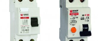
RCDs should also be distinguished by type. There are only two of them - electromechanical and electronic. The main working unit of the first is a magnetic circuit with a winding. Its action is to compare the values of the current going into the network and returning back.
There is such a function in the second type of device, but it is performed by an electronic board. It only works when there is voltage. Because of this, the electromechanical device protects better.
The electromechanical type device has a differential transformer + relay, and the electronic type RCD has an electronic board. This is the difference between them
In a situation where a consumer accidentally touches a phase wire and the board turns out to be de-energized, if an electronic RCD is installed, the person will come under voltage. In this case, the protective device will not work, but the electromechanical device will remain operational under such conditions.
The subtleties of choosing an RCD are described in this material.
Purpose of the introductory machine
The need to install a circuit breaker is determined by the protective system of electrical wiring from overload and the danger of short circuits. The input machine blocks the possibility of a complete blackout at home.
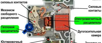
The input circuit breaker protects the wires from overheating, which can cause a fire hazard. The cause of cable overheating is usually long-term loads on the entire electrical network of the facility. The circuit breaker contains a thermal and electromagnetic release that prevents overheating of the wires. The switching device is necessary to de-energize the building in the event of repairs or local network failures.
The nuances of installing a protective device
Connecting an RCD in an apartment or house requires compliance with several rules:
- For several groups of consumers it is necessary to install one RCD and individual circuit breakers.
- If there are several RCDs, each of them will need a zero output bus.
- The TN-C system does not need to be zeroed.
- For “wet groups” it is mandatory to install a protective device with a shutdown rating of 10 mA.
- 30 mA devices are suitable for household appliance outlets that operate with water.
- The zero terminal is located on the right side of the device and is marked with the letter N. It should not be confused with the phase (index L).
- Input can be made to the lower or upper terminals.
- The classic circuit is implemented using a top input and a bottom output.
- Each RCD requires a personal zero block to which all working neutrals are connected.
- For lines with ripple currents, type A devices are required.
You can check the health of the system by pressing the “Test” button.
A protective shutdown device is needed to protect against overloads and short circuits. Due to the lack of response to overcurrents, it is installed in combination with a difavtomat. Connection diagrams allow installation of devices in any order. The only condition is the choice of the appropriate denomination.
Types of input devices
There are two types of protection devices:
- 2-pole in single-phase network;
- 3-pole in a three-phase network;
- 4-pole in a three-phase network.
Most electricians prefer to install a four-pole circuit breaker in a three-phase network. Because in this case, when overheated, the neutral conductor is disconnected along with the linear conductors. Sometimes you can find a three-pole circuit breaker located at the input, during which only linear conductors are disconnected.
Advice: you should choose a device that is triggered when the norm is exceeded by 1000A: this is how much it can withstand.
Connecting two-pole and three-pole circuit breakers
The principle of connecting two-pole and three-pole circuit breakers is exactly the same as in the case of a single-phase packet switch.
And if the question arises of how to connect a three-phase machine, then you should perform all the operations that were carried out with a device designed for a single-phase network. In the same way, strip the wires, crimp them using lugs and a press, and install each wire on the corresponding fixed terminal, and then clamp it with a screw clamp. If a three-pole circuit breaker is installed in a production facility where further connection of asynchronous or synchronous motors is planned, then after installation the phase rotation should be checked using a special device - a phase indicator. If the phases are reversed, the motor will begin to rotate in the opposite direction.
If you do not know how to connect a two-pole machine, then the principle of connecting it is the same as when installing an RCD. Standard places are provided for the connected phase and neutral wires.
It should be immediately clarified that the price for installing single-pole, two-pole and three-phase circuit breakers in Moscow varies. Therefore, it is necessary to take into account the types of switching equipment that will be installed in the panel in the future.
Principle of operation
Usually a limit is set on the electricity consumption of a certain house or apartment. It is indicated when concluding an agreement between the energy supplier and the homeowner. Thus, if the design documentation indicates a consumption level of 25A (amps) in a single-phase network, then this means limiting the energy to 5.5 kW. The input circuit breaker will automatically de-energize the house if the limit is exceeded - this operating principle allows you to minimize the likelihood of a fire hazard.
How to choose a machine based on current strength
We already know that all the electrical current to power the object will flow through this switch. According to Ohm's law, it is clear that the load must be summed up based on all consumers in the house (apartment). Calculating this value is quite simple.
Tip: It is not necessary to calculate energy consumption by summing up the power of all electrical appliances.
Of course, you can turn on the boiler, electric oven, air conditioner and iron at the same time. But such a “celebration of life” will require powerful electrical wiring. And the technical conditions for such input power will cost significantly more. For energy supply organizations, tariffs for coordinating connections grow linearly depending on the number of kilowatts.
For a typical apartment, we can assume the simultaneous operation of a refrigerator, TV, computer, and air conditioner. In addition to them, it is permissible to turn on one of the powerful appliances: a boiler, an oven or an iron. That is, the total power of electrical appliances will not exceed 3 kW. We don’t take lighting into account; today, every home has energy-saving lamps.
This is interesting: if you go back 20–30 years ago, when each chandelier had only incandescent lamps, a two-room apartment with full lighting could spend 500–700 W on light alone.
Usually, for a power reserve (force majeure circumstances are possible), 20–30% is added to the calculations. If you forget to turn off the boiler and start using the iron while the air conditioner is running, you won’t have to run to the electrical panel to restore the power supply. It turns out: 4 kW divided by 220 V (according to Ohm’s law), current consumption 18 A. The nearest circuit breaker is rated 20 A.
For reference: most manufacturers of electrical products produce circuit breakers with the following operating current ratings:
2 A, 4 A, 6 A, 10 A, 16 A, 20 A, 25 A, 32 A, 40 A, 50 A, 63 A...
Selection of circuit breaker rating
The rating of the input circuit breaker must be greater than the rating in apartment circuits. This allows you to avoid turning off all electricity if the protection works in only one of the apartments. The machine is placed on a meter with a standard size of 25 amperes.
The maximum allowable limit is 63 amps, and is usually only found in switchgear in high-rise residential complexes. How many amperes are needed is usually calculated based on the number of apartments.
The sequence of correct connection of the machine
Before you learn how to install the machine correctly, you need to stock up on the most necessary tools. If in the future electrical installation turns into the main type of income, then the following list of tools will not be enough.
- Phillips and flat head screwdriver. Preferably dielectric.
- Indicator screwdriver.
- Monter's knife.
- Screwdriver.
Professional craftsmen also have crimping pliers in their bins, and instead of a fitter's knife, they most often use a special knife for stripping insulation. This is not only more convenient, but also allows you to get the job done faster.
Step #1: DIN Rail Mounting
Do-it-yourself installation of a DIN rail in a panel takes 10-15 minutes. The main condition for fast work is the presence of a good screwdriver, preferably with an autonomous battery.
There are three main types of DIN rails:
- Ω-type. Products of this form are considered the most common, and any circuit diagram for connecting machines in a panel implies the presence of such a product.
- C-type. The ends of the product are bent inward.
- G-type. This rail is similar to the C-shape, but with only one shorter side.
The sequence of installing a DIN rail in an electrical panel:
- Mark the location of the DIN rail in the panel.
- Place the DIN rails on the metal surface and secure them on one side using tex, a special self-tapping screw.
- Align the rail using a building level and secure it on the other side.
If necessary, the DIN rail can be cut to any length, but this product is mainly sold in 2-meter lengths.
Step No. 2: installing the machine on a DIN rail
The simplest procedure in the entire topic “How to connect a machine in a panel.” On each circuit breaker, on one side (usually the bottom) there is a special plastic latch. It must be removed, installed on the DIN rail and pressed until it clicks. After this, the circuit breaker will be securely fixed and you can proceed to connecting it.
Step No. 3: connecting the machine to the network
To find out how to correctly connect the machine in the electrical panel, you must first read the paragraph, which discusses in detail the question of whether the package should be connected from below or from above. As the regulatory documents say, voltage must be applied to the fixed contact of the switching device, and most often this contact is located on top.
Before connecting a single-pole or double-pole circuit breaker to the network, it is necessary to remove the insulation from the wire, crimp it together with the tip and make sure, using an indicator screwdriver, that there is no voltage coming to the packet.
After this, insert the securely pressed tip into the standard connection point of the machine and clamp the connection point using a bolt specially provided by the manufacturers. Check the quality of the connection by moving the wire without applying unnecessary force. If the installation is done correctly, then the machine can be turned on and checked whether everything is working in the apartment.
Installation of an introductory machine
It doesn’t really matter whether the machine is installed after the meter or before it. The only point is that installation up to the electric meter requires mandatory sealing. Supplementing the meter with installed fuses is also necessary.
Important! The filling procedure is carried out using a special box. Otherwise, you need to purchase special panel equipment with a cell in which you can install an automatic input switch.
When positioning, it must be taken into account that the input conductor is laid exactly to the circuit breaker and is susceptible to the following loads:
- lighting;
- sockets;
- number of connected electrical appliances;
- Technical equipment.
All loads must be summed up to select a three-phase input device, which is needed to avoid overheating of the wires.
Automatic machine to the meter or how to properly connect an electric meter in a private house
The other day I partially changed the wiring in my private house and decided to immediately change the electricity meter.
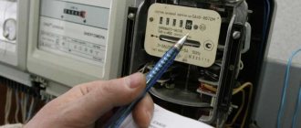
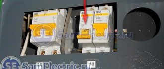
The house is powered by electricity from one phase and I bought a single-phase electricity meter. It is called the SEO-1.20D meter, the maximum current is 80 amperes. The counter is shown in the picture. For information on what and how to do, I went to the local branch of the energy sales company and wrote a statement there that I was removing the old electric meter,
which means I will put a seal on it and will install a new electric meter in its place. And right there in the office, I told the energy sales workers that I wanted to install
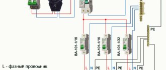
automatic switch before the meter, i.e. at the entrance of electricity into the house from the street side and a residual current device (RCD) after
electrical meter. To which they categorically forbade me to place the machine before the meter, despite my surprise and indignation.
According to the rules (PUE), and also for safety reasons and generally according to normal logic, the circuit breaker should be located at the very input of 220 volt electricity into the house.
I probably spent half a day in the energy sales office convincing, proving, arguing.
To which they answered me, like we don’t have such information and that if there is a switch before the meter, then I can theoretically connect to it and steal electricity.
Just at the peak of our dispute, their chief engineer accidentally came into the office and said that a circuit breaker was not only possible, but also necessary to be installed at the entrance to the house, i.e. to the electricity meter.
Only this machine must have the technical ability to be sealed, i.e. it should be in a special box, a shield with a screw-on lid.
By the way, such small electrical panels are sold in a large assortment in electrical stores.
What I mean is that energy sales workers artificially create difficulties out of nowhere, literally putting a spoke in people’s wheels because of their incompetence, without having information about what and how can and should be done, and perhaps without knowing or understanding the essence of the issue.
I ended up installing a 50 amp pre-meter circuit breaker on the street right next to the 220 volt input to the house. At 50 amperes because I plan to carry out welding work with an inverter welding machine, which is plugged into the outlet naturally after the meter and the current in the 220 volt network during welding will theoretically rise to 30-40 amperes.
I placed this switch in a special plastic shield, bought in a store for 150 rubles.
And inside the house, in the storage room, I installed an electric meter and after it (an RCD) a 32-amp residual current device. These two switches are connected through a counter, as it were, with a VVG wire of 2x10 squares. A wire of 2x6 squares is suitable for the welding socket, and for the rest of the sockets and lighting, somewhere around 2x2.5 and somewhere around 2x1.5 squares.
When I finished all this work, I invited an energy sales worker. He quickly sealed the new electric meter, covering with adhesive tape the bolt that tightens the meter cover and the automatic switch on the street, or rather the electrical panel with the switch. He also glued this special adhesive tape to the body and cover of the switchboard (see picture).
Replacing a packet switch with an automatic one
Dismantling of old equipment is usually caused by burnt contacts in old-style houses. It is impossible to repair such a breakdown, which is why it is necessary to replace the batch switch with a modern automatic analogue.
There are two methods used for repair:
- The burnt switch is dismantled, but the wires are simply twisted together - the shield continues to work, but has no protection against overheating.
- The switch is replaced with a circuit breaker.
The switching circuit of the metering device does not change: the selected input machine is connected in the same way as its predecessor.
Three-pole and four-pole VA
Devices of this type are installed in 380 Volt power supply networks and allow you to simultaneously switch all phases at once. Their design may include special arc-extinguishing chambers that provide switching of large loads (significant currents). The figure below shows the appearance and schematic diagram of this device.
Three-pole input machine
When depicting it graphically, the rules for designation and marking of supply wires, regulated by current standards, are used, consisting of the following:
- According to these regulations, the phase conductors are designated as A, B and C, and also differ in color by the sheath (insulation) protection;
- The set of colors can be arbitrary, but the most commonly used colors are red (brown), green and yellow;
- When such a machine is turned on at the entrance to a facility (in a private house or garage workshop, for example), the neutral wire in blue insulation is passed past it and connected directly to the corresponding terminal of the electric meter.
If it is necessary to switch all four wires of the 380 Volt supply cable, you will need to install a 4-pole circuit breaker used at the entrance to this facility. This VA connection option provides additional protection for the serviced network via the neutral wire.
A typical circuit breaker is usually designed for rated switched currents of the order of 63-100 Amperes (their exact value depends on the size of the load connected to a given network).
To correctly calculate this value, it is necessary to inspect all three-phase units available at the site (electric motors, pumps, etc.), taking into account the active and reactive power they consume. After this, it remains to determine the currents flowing through their circuits in extreme operating conditions, and then summarize the results.
In the final part of the review, we note that if the power consumed by this facility increases above the established norm (15 kW), special permission and additional payment will be required. After receiving it from the relevant authorities, it will be possible to install an introductory machine with the required denomination.
We connect the wires to the machine - a cable with a monolithic core
How do most users connect machines in the control panel? What mistakes can be made in this case? Let's look at the most common errors here.
Error – 1. Insulation coming into contact.
Everyone knows that before connecting the machine in the panel, you need to remove the insulation from the connected wires. It would seem that there is nothing complicated here, I stripped the core to the required length, then we insert it into the clamping terminal of the machine and tighten it with a screw, thereby ensuring reliable contact.
But there are cases when people are perplexed why the machine burns out when everything is connected correctly. Or why the power in the apartment periodically disappears when the wiring and filling in the panel are completely new.
One of the reasons for the above is that the wire insulation gets under the contact clamp of the circuit breaker. Such a danger in the form of poor contact carries the threat of melting of the insulation, not only of the wire, but also of the machine itself, which can lead to a fire.
To eliminate this, you need to monitor and check how the wire is tightened in the socket. Correct connection of circuit breakers in the distribution board should eliminate such errors.
Error - 2. You cannot connect several wires of different sections to one AB terminal.
If there is a need to connect several machines standing in the same row from one source (wire), a comb bus is ideally suited for this purpose. But such tires are not always at hand. How to combine several group machines in this case? Any electrician, answering this question, will tell you to make homemade jumpers from cable cores.
To make such a jumper, use pieces of wire of the same cross-section, or better yet, do not break it along its entire length. How to do it? Without removing the insulation from the wire, form a jumper of the desired shape and size (according to the number of branches). Then we strip the insulation from the wire at the bend to the required length, and we get an unbreakable jumper from a single piece of wire.
| Never connect machines with jumpers and cables of different sections. Why? When tightening the contact, the core with a large cross-section will clamp well, and the core with a smaller cross-section will have poor contact. As a result, the insulation melts not only on the wire, but also on the machine itself, which will undoubtedly lead to a fire. |
An example of connecting circuit breakers with jumpers from different cable sections. The first machine receives a “phase” with a 4 mm2 wire, and the other machines already have jumpers with a 2.5 mm2 wire. The photo shows that the jumper is made of wires of different sections. As a result, poor contact, increased temperature, melting of insulation not only on the wires, but also on the machine itself.
For example, let's try to tighten two wires with a cross section of 2.5 mm2 and 1.5 mm2 into the terminal of the circuit breaker. No matter how hard I tried to ensure reliable contact in this case, nothing worked. A wire with a cross section of 1.5 mm2 was hanging loosely.
Another example in the photo is a difavtomat, into the terminal of which they plugged two wires of different sections and tried to tighten the whole thing securely. As a result, the wire with a smaller cross-section dangles and sparks.
Error – 3. Formation of the ends of wires and cables.
This point most likely refers not to an error, but to a recommendation. To connect the cores of outgoing wires and cables to the machines, we remove the insulation from them by about 1 cm, insert the bare part into the contact and tighten it with a screw. According to statistics, 80% of electricians make connections this way.
The contact at the junction is reliable, but it can be further improved without wasting time and money. When connecting cables with a monolithic core to circuit breakers, make a U-shaped bend at the ends.
This formation of the ends will increase the area of contact of the wire with the surface of the clamp, which means the contact will be better. PS The inner walls of the AB contact pads have special notches. When the screw is tightened, these notches cut into the core, thereby increasing the reliability of the contact.
Actions when turning off the machine
Inexperienced users, when the network is disconnected, automatically rush to restore the voltage supply by turning on the device. But it is not recommended to turn on the device without establishing the reason for the shutdown.
The machine may operate for the following reasons:
- overheating of sockets and switches as a result of loose contact;
- excess load due to the simultaneous activation of several powerful consumers;
- poor contact in wiring connections.
To determine the malfunction, you need to inspect your home network, make sure there is no heating or smell of burnt plastic. If the heating point is established, the necessary repairs are carried out.
When triggered by excess load, it is necessary to limit the number of switched on consuming devices. The device turns on after a complete check of the network and the cause of the shutdown has been eliminated.
The device may operate due to its failure, which is determined by visual inspection of the switch. If there is heating of the contacts, traces of thermal deformation, charring of the terminals, the machine must be replaced.
Serviceable and correctly selected circuit breakers will ensure normal operation of the home electrical network, eliminating the risk of damage to household appliances. But if the owner does not have electrician skills, it is worth contacting a qualified electrician to install or replace the machines.