The role of an ordinary switch, that is, breaking the circuit, is a secondary task of the circuit breaker.
And if you abuse frequent shutdowns using automatic machines, especially without disconnecting the load from the sockets, the contacts inside the automatic machine gradually burn out.
The contacts will eventually burn and blacken, losing their rated capacity. As a result, after some time, you will have to change the circuit breaker. If you do not do this, another short circuit may cause the machine itself to ignite.
Therefore, load switches were developed to improve the safety of electrical panels and the reliability of power supply.
Modular load switch or input circuit breaker? 4 advantages of use.
Surely many of you have used circuit breakers. There were no problems turning the lights on and off using such switches. But you should know that, first of all, circuit breakers were created not for frequent switching operations, but to protect electrical wiring and pantographs from overcurrents.
The role of an ordinary switch, that is, breaking the circuit, is a secondary task of the circuit breaker.
And if you abuse frequent shutdowns using automatic machines, especially without disconnecting the load from the sockets, the contacts inside the automatic machine gradually burn out.
The contacts will eventually burn and blacken, losing their rated capacity. As a result, after some time, you will have to change the circuit breaker. If you do not do this, another short circuit may cause the machine itself to ignite.
Therefore, load switches were developed to improve the safety of electrical panels and the reliability of power supply.
Conclusion
The switch handle sticking out of the switchboard has become a definite feature of old electrical distribution networks. But recently, switches are used less and less. After all, their main advantage, price, has become less and less important lately.
Automatic machines are more functional, safer, less cumbersome and easy to use, so they are slowly but surely winning places in switchboards from circuit breakers. After all, everywhere you can install a machine instead of a switch, but it is not always possible to install a switch instead of a machine.
What is a load switch?
In short, this is a mini switch. Many people have probably at least once in their life seen a metal box with a handle coming out of its side. When the handle is raised, power is supplied to the network, when lowered, a shutdown occurs. And if you had to look inside, you could see large copper knives, which are the moving contacts, and jaws, the fixed contacts into which the knives fit. A distinctive feature of such a device is that you can visually observe the disconnection of the electrical circuit.
The modular load switch, of course, has a different shape and design, and is much smaller in size, but it works on the same principle. Therefore, like a disconnector and high-voltage switches, it belongs to switching devices.
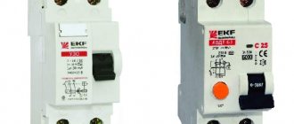
It is sometimes difficult to determine by the name what kind of device it is, since each manufacturer in different countries uses its own name. Therefore, it is better to check with the seller. Sometimes you can see the letters VN in the name, which help determine the device, for example, load switch VN-32 3P 40A IP20.
The abbreviation VN means load switch, 3P indicates the number of poles, in this case there are 3. Then comes the rated, operating current, this is the operating value for the load switch. For example, load switch VN-32 is available with the following current ratings: 20; 25; 32; 40; 63 and 100 A.
The last one to show is the protection class (numbers IP-20). This is an indicator of the degree of human protection when using this device. For the average user, it is not important, since stores sell electrical devices that are acceptable for general use.
Types of devices
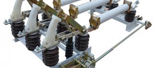
Vacuum load switch
Switches are divided according to the arc extinguishing method. There are the following types:
- Vacuum. They work on the properties of a vacuum in which the arc does not propagate.
- Autogas. The arc is extinguished by the action of gases that are released at high temperatures in the chamber.
- Autopneumatic. The air is compressed, causing the arc to be extinguished.
- Electromagnetic. The direction of the arc changes under the influence of the electromagnetic field.
- Electric gas. Quenching occurs in an electrical gas environment consisting of sulfur hexafluoride.
By the number of poles we can distinguish:
- single-pole;
- bipolar;
- three-pole devices.
- thermal;
- semiconductor;
- electromagnetic;
- combined.
According to the installation method, switches are classified into stationary and retractable. There are devices for indoor and outdoor installations. The devices can be mounted on a DIN rail, wall or electrical panel.
Features of the use of automatic machines and switches
Before connecting a switch, circuit breaker or other switching device, you must clearly understand its purpose. To do this, let's look at the purpose of the positions we are interested in, as well as the most common places for their installation.
- Let's start with a simpler switch. They are intended for installation in electrical installations of predominantly closed type. Modern models, of course, have good protection from moisture and dust and do not have live parts accessible to touch, but it is still better to install switches in switchboards.
- The switch is designed for switching networks without voltage, under voltage and sometimes under light load. Let's explain this in simpler terms: you can operate a switch when all electrical installations powered by it are turned off. In this case, by turning off the switch you relieve the voltage from them.
- In order to turn off the switch under load, it must have arc chutes. And even in this case, it is not recommended to switch significant currents with them. The maximum is the load of the lighting network, or the no-load current of the transformer.
Note! Surely you can hear stories about how powerful engines were turned off by switches, how the lighting of several houses was turned off, and the like. But believe me, this is a matter of chance. And if this happens once, then a second time can lead to burnout of the switch and serious injuries to the experimenter. That is why, according to the PUE standards, switches must be installed in places inaccessible to unqualified personnel.
- Now, as for the machines. These switching devices are designed for switching circuits without voltage, under voltage and under load. That is, we can automatically turn off the load corresponding to its rating without any problems. Moreover, thanks to the presence of built-in protections, the machine is able to turn itself off if the nominal parameters are exceeded. No switch is capable of this.
- But slot machines have one, although not significant, minus. Visually determining the position of its contacts is quite difficult, because, unlike a switch, they are not visible. That is, once you turn off the machine, you cannot be sure that it is turned off. That is why labor safety standards require a preliminary check of the absence of voltage on the contacts of the machine.
- With a switch, everything is simpler - you can visually see that it is turned off. That is why switches are often used as input switching devices on a distribution board. And after them, automatic machines are installed that not only switch each specific group of consumers, but also protect it.
Connection rules
On power lines, the device is installed in front of the transformer. In residential buildings, the switch is placed in the distribution panel or other place for each apartment separately. In the apartment itself, the switches are installed in front of the meter, but they can also be installed after the meter. Be sure to install the switch according to the diagram in front of other protective devices (plugs, circuit breakers).
In plants, factories and other production facilities, the switch is placed next to machines that may require emergency shutdown.
Advantages and disadvantages
The main positive qualities of load switches include:
- ease of manufacture and operation;
- the cost of the switch is lower than other similar products;
- convenience of switching currents on and off;
- overcurrent protection;
- there is a visible gap between the contacts;
- safety.
The disadvantages of load switches include the ability to switch rated powers. Work with emergency currents is not carried out. Also, gas-type switches have a short service life.
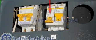
Current limiting class
The number after the short-circuit current (3 or 2) is the current limiting class.
A circuit breaker with this function does not allow the short circuit current to reach its maximum value and trips at the earliest possible stage.
That is, this figure shows how quickly the electric arc is extinguished inside the device, preventing individual elements and parts from heating up to extreme temperatures and contributing to a fire.
Class '2' limits short-circuit current within half a half cycle
Class '3' within 1/3 half cycle
Roughly speaking, an automatic machine with a “C” will cope with the consequences of a short-circuit current faster than with a “D”. In terms of time, this can be reflected in the following table.
Devices with “first” class are not marked in any way or with any numbers.
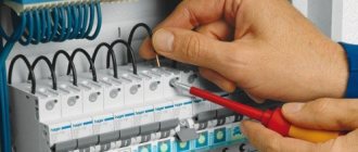
All of the above markings are located on the front side. Now let's move on to the side edge. There is also a lot of useful information there.
Switches and disconnectors
A switch is a non-automatic switching device with a manual drive and metal blade contacts, used in electrical circuits for their switching (on/off).
Product out of stock
- Seal
Switch device.
The design of the switch depends on its type. For example, devices with a central handle only turn off electrical circuits.
Typically the switch consists of:
- contact type knives;
- smooth type inserts;
- racks of combined and contact type;
- terminals through which the switch is connected.
The main part of the switch is the panel, which is made exclusively from dielectric materials. Several stands and jaws are installed on the panel. The knife switch is an electrical movable contact that is rigidly fixed to the shaft device.
When the device is turned on, conductive type knives are installed in the jaws, which are the stationary parts of the switch. All working poles are connected and they come into contact with each other.
The design of the switch depends on the method of switching on the device. There are lever-drive switches, in which the knives begin to move by turning the lever. The second type of switches are devices with a central handle. They are used solely to switch off an energized electrical circuit.
Many modern switches provide protection for outgoing lines (consumers) from overloads and short-circuit currents. The protection is made using PN fuses (simply inserts).
Using a switch
- The use of switches is associated with turning on and off an electrical load in a network where a large amount of current is present.
- Open type switches are used to close or open a circuit without load.
- Switches with a handle, on the contrary, are used in electrical circuits with a large load.
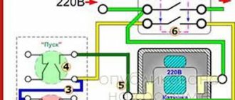
- Provided that the switch contains a central casing, it is used as a starting device for an electric motor.
- Central side or lever type switches are used to operate on the central distribution board.
- Switches are used for infrequent automatic switching on or off of an electrical circuit.
- Switches with a side, central handle are used in an electrical network whose power does not exceed 500 W.
- Switches are used for installation on a switchgear, electrical cabinet or electrical panel, to control an electrical circuit or power circuit.
- Some models are installed directly on the transformer power station.
Characteristics of thermal relay
The main characteristic for thermal relays is the response time, which depends on the load current. In other words, this characteristic is called time-current. If we consider the general case, then before the load is applied, current I will flow through the relay. In this case, the heating of the bimetallic plate will be q
When checking this characteristic, it is very important to consider from what state (overheated or cold) the device is triggered. In addition, when testing these devices, it is very important to remember that the plate is not thermally stable when a short circuit current occurs
Thermal relays are selected as follows. The rated current of such a protective device is selected based on the rated load of the electric motor. The selected relay current should be 1.2-1.3 of the rated motor current (load current). In other words, such a device will work if the load is between 20 and 30% within 20 minutes.
It is very important to understand that the operation of the thermal relay is significantly influenced by the ambient air temperature. Due to an increase in ambient temperature, the operating current of this device will decrease
If this indicator differs too much from the nominal value, then it will be necessary to either carry out additional smooth adjustment of the relay, or buy a new device, but taking into account the actual ambient temperature in the working area of this unit.
To reduce the influence of ambient temperature on the magnitude of the current operation, it is necessary to purchase a relay with a large rated load value. In order to achieve proper functioning of the warm device, it should be installed in the same room in which the controlled object is located. However, you need to remember that the relay reacts to temperature, and therefore it is prohibited to place it near concentrated heat sources. Such sources are considered to be boilers, heating sources and other similar systems and devices.
What is an automatic machine
A circuit breaker is also a switching device, but already designed for switching electrical circuits and protecting them. It has two releases - thermal and electromagnetic. Thermal switches off the load in case of minor overloads, and electromagnetic switches off in case of short circuits on the line or connected equipment. This reduces the risk of fire and damage to cable lines.
Currently, automatic switches are installed at the entrance to houses and apartments. They also come with different numbers of poles. If three phases and three wires are connected to the machine, respectively, then they say that it is three-pole. And if the device has only two terminals for connecting conductors, then it is single-phase or single-pole.
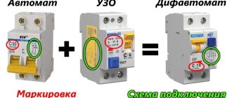
Depending on the design and parameters of the releases, time-current characteristics are distinguished - the value at which the protected circuit will automatically switch off. Indicated by letters of the Latin alphabet. For example, marking C16 means that this is a circuit breaker with a rated current of 16A with a time-current characteristic of C, which is the main difference between devices with different rated currents.
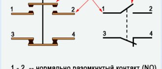
Its image in the diagram is shown below.
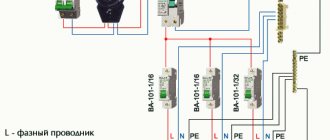
You can see a typical connection diagram for devices with different numbers of poles in the following electrical panel diagram:
Undisconnected lines in the shield
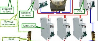
Using a load switch inside the apartment electrical panel, you can de-energize all electrical wiring. This can be done for electrical safety purposes when leaving home. It is impractical to turn off some electrical appliances. For this purpose, an undisconnected line is left. In the figure below there are 2 load switches, one of which can turn off all the wiring of the apartment, and the other leaves the refrigerator in operation. In addition, there are also constantly working security alarm and video surveillance systems.
Scheme of an apartment switchboard with an unswitched line
The diagram shows the phase and neutral wires in red and blue. You can only turn them off, and the ground (yellow-green color) always remains connected.