The ferroresonant voltage stabilizer is widely used in various fields of industry and in everyday life. Such ferroresonant voltage stabilizers make it possible to equalize alternating voltage. Also, such devices have disadvantages that need to be considered.
Currently, there is a standard according to which the output voltage should be in the range of 0.9-1.05 from the nominal value. This standard was determined a long time ago and all devices must comply with it. The output network voltage should be 197-230 V. Before purchasing, you should familiarize yourself with single-phase models.
Ferroresonance phenomena in electrical networks
The main factors that give rise to ferroresonance phenomena in electrical networks are elements of capacitive and inductive types.
They are capable of forming oscillatory circuits during switching periods. This effect is especially noticeable in power type transformers, linear booster transformers, shunt circuits and similar devices that are equipped with massive windings. This phenomenon comes in two types: resonance of currents and voltage. Voltage ferroresonance is possible when there is inductance in the network, characterized by a nonlinear current-voltage property. This characteristic is characteristic of inductors, where the cores are made from ferromagnetic components. This is especially true for rectifiers from the NKF line. This negative phenomenon is caused by a small indicator of resistance of ohmic and inductive types in relation to power transformers.
Ferroresonant UPS
Ferroresonant UPS
are represented in Russia by a single series of devices.
These are Ferrups from Best Power Technology. Thus, the task of considering this type of UPS
is simplified and comes down to talking about the circuit and characteristics of this series
of UPS.
Figure 15 shows a block diagram of a ferroresonant UPS
.
Rice. 15. Block diagram of a ferroresonant UPS
Compare this diagram with the UPS
, interacting with the network.
You will see a lot of similarities. In fact, there is one main difference - instead of an autotransformer with taps, a ferroresonant transformer appeared in the ferroresonant UPS
.
But its presence radically changes the operation of the UPS
and allows Ferrups to be classified as a different class of device, providing a higher level of load protection.
Since it is the transformer that largely determines the properties of this UPS
, let us first consider in more detail the operation of a ferroresonant transformer.
Properties of a ferroresonant transformer
Joseph Sola's magnificent invention, the ferroresonant transformer, was originally designed to function as a voltage stabilizer. The first patent (1938) for this device was called “constant voltage transformer.”
A ferroresonant transformer is a combination of two magnetic circuits with a weak connection between them. The output circuit contains a parallel oscillating circuit, fed from the primary circuit to compensate for the power supplied to the load.
The process of ferromagnetic resonance itself is quite similar to resonance in linear circuits consisting of inductances and capacitors. In a nonlinear circuit such as a ferroresonant transformer, resonance is used to reduce voltage fluctuations in the secondary circuit.
Any magnetic device is a device with a nonlinear characteristic. If the magnetic flux is less than a certain limit value, then the magnetic resistance of the device is proportional to the magnetic flux. If the magnetic flux exceeds the limit value, then the magnetic resistance of the device increases abruptly (they say that saturation occurs).
In a ferroresonant transformer, one of the magnetic circuits (output) is in saturation mode, while the other (input) does not reach saturation. Large changes in input voltage cannot lead to significant changes in output voltage due to saturation of the output magnetic circuit.
Everyone remembers, of course, Soviet voltage stabilizers, which were used to power televisions in rural areas, and often in cities. They are built on the basis of a ferroresonant transformer. These regulators had (and still have) an excellent input voltage range (from about 130 V at part load). They also have many disadvantages. The main ones are huge harmonic distortion of the output voltage and unfavorable thermal conditions when there is no load.
Modern ferroresonant transformers are somewhat more complex than the one invented in 1938. They have a neutralizing winding specifically designed to reduce harmonic distortion in the output voltage.
The neutralizing winding is designed in such a way that it generates harmonics that are in antiphase to the harmonics in the main output winding. The correct selection of the number of turns and magnetic resistances allows, due to the series connection of the neutralizing and main output windings, to completely compensate for harmonic distortion. Moreover, even if the input voltage has strong harmonic distortion, the use of a ferroresonant transformer can almost completely reduce the harmonic distortion of the output voltage.
The current consumed by a ferroresonant transformer is almost sinusoidal. The current harmonic distortion coefficient is very low. Most importantly, the harmonic distortion factor remains low regardless of whether the load connected to the transformer is linear or non-linear. The ferroresonant transformer owes this property to the weak coupling between the input and output magnetic circuits.
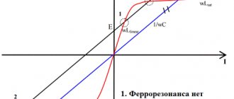
Figure 16 shows the main characteristic for any voltage stabilizer - the dependence of the output voltage on the input voltage.
Rice. 16. Input-output characteristics for a ferroresonant transformer.
Actually, the figure shows half of the symmetrical characteristic: when the input voltage increases and decreases in the vicinity of the midpoint, the ferroresonant transformer behaves similarly.
At full load, the ferroresonant transformer provides voltage stabilization with an error of about 1% when the input voltage changes by 15% relative to the rated one. The ferroresonant transformer provides the greatest capabilities if its load is less than the rated load. Thus, at a load of about 50%, the range of input voltages expands incredibly: to more than 50% of the rated input voltage.
A special feature of the input characteristics of the transformer is that even in idle mode (no load), the resonant circuit of the ferroresonant transformer is energized and consumes about 10% of the rated power of the transformer. In general, in thermal terms, the idle mode is the most stressful for a ferroresonant transformer.
A ferroresonant transformer can withstand any overload. As the load resistance decreases, the output voltage decreases and the transformer does not overheat. Even during a short circuit, the transformer output current is limited to approximately 150-200% of the rated current. The total power consumed by the transformer from the network during a short circuit does not exceed 10% of the rated value.
The disadvantage of a ferroresonant transformer is the dependence of the output voltage on the frequency of the electrical network. When the frequency changes by 1%, the output voltage changes by approximately 1-1.5%. An increase in frequency leads to an increase in voltage.
In a ferroresonant UPS
In addition to voltage stabilization, the ferroresonant transformer also performs several other functions.
In the event of a power failure, a ferroresonant transformer supplies the computer with electricity using the energy stored in its magnetic field. This lasts 8-16 milliseconds. This time is sufficient for all necessary switchings and for the inverter to reach its nominal operating mode. Thus, ferroresonant UPS
provides truly uninterrupted power supply to the computer, having the properties of
an on-line UPS
.
The ferroresonant transformer also provides effective suppression of noise and pulses, which makes it possible not to use other special circuits to suppress them.
Ferroresonant transformer used in UPS
, has independent primary and secondary windings, i.e.
provides complete galvanic isolation of the load from the electrical network. This property increases the reliability of uninterruptible power supply systems and allows the use of ferroresonant UPSs
to protect computer networks, including those located in different buildings.
Transformer for ferroresonant UPS
is also an input device: there are no vulnerable semiconductor elements at the Ferrups input.
Therefore, with strong fluctuations in the input voltage, including significant pulsed loads, this UPS
does not fail.
There are modifications of Ferrups designed for connection not to phase, but to linear voltage (i.e. voltage 380 V). The output voltage of these UPSs is
equals 220 V. Connecting
the UPS
to two line wires has several advantages and brings these modifications of ferroresonant
UPS
closer to
a UPS
with a three-phase input.
Among the advantages: no phase imbalance when connecting a significant single-phase load, a wider range of UPS
due to a smaller change in line voltage compared to phase voltage, no neutral overload.
Operating modes of ferroresonant UPS
Ferroresonant UPS
can operate in one of three modes.
Power conditioner mode
The simplest case of using a ferroresonant UPS
- this is to switch it to power conditioner mode.
The UPS
this operating mode using a switch on the control panel.
As the name of the mode suggests, at this time the UPS
performs the functions of an electrical network conditioner: it stabilizes voltage and filters electrical noise and impulses.
UPS
inverter is blocked.
Strictly speaking, in this operating mode the device is not an uninterruptible power supply, since if the voltage in the electrical network disappears, it will not be able to support the operation of its load.
Network operation
UPS mains mode
works in the same way as in power conditioner mode, stabilizing and filtering the mains voltage.
UPS rectifier
automatically recharges the
UPS
.
Inverter and UPS
are constantly on alert, and as soon as the network analysis unit detects a network failure that cannot be eliminated using a ferroresonant transformer, the inverter immediately turns on and the
UPS
switches to battery mode.
Battery operation
At the command of the network analysis unit, when a power failure occurs, the UPS
. Switching on is carried out so that the inverter voltage is in phase with the mains voltage. The electrical network is then disconnected from the input of the ferroresonant transformer, but remains under the control of the network control and analysis unit.
When switching to UPS
continues to supply power to the load using the magnetic energy stored in the highly inductive ferroresonant transformer.
At this moment, the ferroresonant transformer acts as a “flywheel” that helps the UPS
“overshoot” the switching point without interrupting the power supply to the load. During the time the inverter enters mode, the output voltage has time to decrease by several percent.
UPS battery mode
, the
UPS
continues to supply voltage to the load, draining battery power.
After the charge is exhausted, when the voltage on the battery becomes less than the minimum permissible, the UPS
turns off the inverter and the load is de-energized.
If the mains voltage is restored before the battery is depleted, the UPS
begins preparations for switching to mains operation. At this time, the control unit monitors the change in the phase difference between the inverter output and the network. At the moment when the phase difference is equal to zero, the ferroresonant transformer is connected to the electrical network, and the inverter stops working.
Control block
Ferrups are controlled by a microprocessor that constantly monitors many parameters. Any Ferrups model can be equipped with a control panel with an alphanumeric display. Models starting with a power of 4.3 kVA are equipped with it as standard.
At any time, any of the approximately 130 values stored in the Ferrups main memory can be called up on the control panel. Some of these quantities are measured by the device: voltage at the input and output of the UPS
, load current, temperature in three places
of the UPS
(inside the case, radiator and transformer), etc.
Other values are calculated based on measurements: battery life, power factor, load power in VA and watts. The third group of values consists of factory-set limits for permissible changes in basic parameters: maximum temperatures, voltages and currents, upper and lower frequency limits, etc. The UPS
memory also stores: the type and number of the device, the operating hours of the inverter, the results of the last test, alarm messages, as well as several parameters that are used to configure
the UPS.
Some of the values can not only be viewed, but also changed. To protect against arbitrary changes of parameters by unqualified personnel, there is a three-level password system. For example, a user password allows you to set the time and date on the microprocessor clock, a service password allows you to configure measured values, etc.
If the recorded parameters go beyond the established limits of the UPS
issues an alarm message.
It is registered in memory and accompanied by a sound signal. Each of the 19 types of emergency messages has its own sound signal, which is a periodically repeating Morse code. Alarm messages are issued, for example, in the event of a battery discharge (two levels of discharge) or its overcharging, as well as (a separate signal) when there is little time left before the battery charge is exhausted, voltages, currents, temperatures exceed the established limits. The performance of several components of the UPS
: batteries, inverter, RAM, temperature sensors.
Using the control panel, Ferrups can be switched to power conditioner mode or battery operation.
the UPS is switched
to battery mode.
The need for such a calculation is due to the fact that the input voltage range of a ferroresonant transformer strongly depends on the UPS
(see Fig. 16).
With a light load, the ferroresonant UPS
switches to battery operation at a voltage of 140-150 V. If
the UPS
is close to the nominal load, switching to battery operation occurs at a noticeably higher voltage (170-180 V).
In general, the Ferrups microprocessor control unit is one of the most advanced devices for this purpose. In addition to the features already noted, it implements a pulsed battery charging algorithm and calculates the expected battery life more accurately than other UPS systems known to me.
Port for communication with a computer
Ferroresonant UPS
equipped with a port for communication with a computer or other devices. This port is designed to transmit and receive relay type signals and RS232 protocol signals.
To communicate with Ferrups, not only a computer with CheckUPS software can be used, but also any terminal (or a computer in terminal emulation mode). This allows you to configure the UPS, even without software or a control panel .
To communicate with the UPS
a special language is used (and is documented in detail in the description), consisting of approximately 40 basic commands (keywords).
Sending a command to the uninterruptible power supply causes a reaction: displaying the requested data on the terminal screen, changing data in the UPS
or switching Ferrups operating modes.
Any information from the UPS memory can be recalled on the terminal or computer screen ,
including alarm messages, any of the parameters, list of parameters.
Using the terminal, you can switch the UPS
to another operating mode, change the time or date, erase recorded alarm messages, etc.
Sometimes a general switch can be installed in a computer room, designed to turn off (including emergency) all equipment at the same time. It is clear that if part of the equipment is powered via a UPS
, then turning off the switch will not lead to equipment shutdown.
The UPS
will respond to this as if it were a normal power failure and will continue to support battery operation of the equipment.
The Ferrups port can be used to provide a special signal to the UPS from additional breaker contacts. After receiving this signal and the voltage disappears, the UPS
will relieve stress from the load.
Turning on the switch will cause voltage to be supplied to the equipment protected by the UPS.
Characteristics of ferroresonant UPS
Power
The Ferrups UPS series consists of 19 models ranging from 500 to 18 kVA
.
Efficiency
Efficiency of a ferroresonant UPS
varies from 85 to 92 percent, depending on power.
Galvanic isolation
FerrUPS not only has complete galvanic isolation between input and output, but also has a uniquely low pass capacitance of no more than 2 pF and according to US national standards can be considered a completely isolated power supply.
Battery life
Ferroresonant UPS
in the standard (minimum) configuration, the battery life at full load is about 6-12 minutes. Battery life can be increased almost unlimitedly by installing larger batteries in the same case or using a separate case for the battery. Unlike most other UPS systems, as Ferrups battery capacity increases, the charger can also be replaced. This allows for short battery charging times even for high-capacity batteries.
Input voltage
As already mentioned, a ferroresonant UPS
not sensitive to output overloads.
Even if there is a short circuit at the output, it does not fail (even without fuses or electronic protection). However, like any single-phase UPS
, Ferrups can be damaged by a significant increase in the voltage at its input (for example, during an emergency increase in voltage in the event of a neutral break).
Most Ferrups models (intended for our electrical network) have a rated input voltage of 220 V. These (as well as all other single-phase UPSs)
, and the previous paragraph applies).
But models starting with a power of 4.3 kVA can be equipped with a special autotransformer that changes the rated input
voltage of the UPS to 380 V.
This means that the UPS
with an autotransformer it can be connected not to phase voltage (220 V), but to linear voltage (380 V).
Linear voltage in a three-phase electrical network is much less susceptible to any changes than phase voltage, even in the event of serious accidents. The possibility of a significant (more than 25%) increase in line voltage is practically absent. Therefore, a ferroresonant UPS
with a 380 V input receives very high resistance to changes in input voltage: i.e.
This UPS
is almost impossible to burn out not only with a short circuit at the output, but also with any changes in the input voltage.
Moreover, this variety of Ferrups gains some of the properties of three-phase UPSs
.
When connecting this UPS
to line voltage, the neutral wire is not used. This unloads the neutral and reduces harmonic voltage distortion.
Surge protection
FerrUPS is tested to Category B of the relevant ANSI/IEEE standard (6000 V impulse, 3000 A). The pulse amplitude reduction factor is 1:2000. Pulse attenuation is based on the properties of a ferroresonant transformer, which, unlike varistor pulse filters, does not wear out.
Noise protection
Ferrups does not have a special noise filter. A ferroresonant transformer is used to filter noise.
Attenuation of general noise reaches 120 dB, normal noise – up to 60 dB.
Voltage waveform
Total harmonic distortion of ferroresonant UPS
does not exceed 5% for linear load. Distortion of the input voltage shape has little effect on the output voltage shape: it remains sinusoidal.
Crest factor (amplitude factor) of load
Ferroresonant UPS
(again due to the properties of its transformer) has features when working with switching power supplies for computers and other non-linear loads.
When powered by Ferrups, computer power supplies operate with a reduced current consumption crest factor (i.e., the peak value of the consumption current decreases and the pulse width increases). Thus, the computer's current consumption approaches sinusoidal.
Current consumption amplitude factor of the ferroresonant UPS
practically does not depend on the nature of the load, so the distortions introduced by computers into the electrical network are reduced.
Reliability
This is one of the important requirements for a UPS
, because it itself is intended to increase the reliability of some equipment.
High reliability of ferroresonant UPS
is determined by its circuit features: the absence of semiconductors at the input, the high resistance of the transformer to voltage fluctuations and absolute protection from short circuits at the output.
According to independent research (Reliability Ratings - a study conducted by surveying users in America), Ferrups has a mean time between failures of about 100 thousand hours. The next UPS
is about half that.
Advantages of a ferroresonant UPS
To the positive properties of a ferroresonant UPS
the following should be included.
- Galvanic isolation.
- Very good protection against noise and nanosecond pulses.
- Protection against distortion of the voltage waveform and microsecond pulses.
- Smooth voltage stabilization.
- Intelligent interface and ability to customize parameters.
- High reliability. There is good reason to consider Ferrups to be the most reliable and most suitable for very harsh UPS
. - Availability of connection to the linear voltage of a three-phase electrical network.
Disadvantages of a ferroresonant UPS
The few disadvantages of Ferrups, as well as its advantages, are associated with the presence of a ferroresonant transformer in its circuit.
- Frequency sensitivity. The Ferrups output voltage, due to the resonant properties of the transformer, depends on frequency: a 1% change in frequency leads to a voltage change of approximately 1-1.5%.
The output current limitation of a ferroresonant transformer can be both a disadvantage and an advantage, depending on the circumstances. The output current of the transformer cannot exceed the rated current by more than 50%. Therefore, it can withstand a short circuit at the output. If a higher current is briefly required to start a device (starting current), then two options are possible: either the startup of the device will be extended over time (soft start), which is often very good, or the device will not start without receiving it from the UPS
the required starting current (for example, an electric motor). When designing an uninterruptible power supply system based on Ferrups, it is necessary to analyze the starting currents of all loads and the sequence of their inclusion so that the startup of one of the powerful devices does not lead to a sharp decrease in voltage on other devices. Typically, for such systems, it is recommended to protect each device (or group of devices) with its own automatic machine with an instantaneous mechanism.
Why ground
Grounding the transformer neutral is necessary to create stable operation of the electrical installation and the safety of people who may be at the substation.
The working grounding on the transformer is part of the protective one. This means that grounding, designed to ensure stable operation of the device, also protects against electric shock.
Electrical installation regulations require that all power transformers be grounded.
In voltage transformers, only the transformer is grounded. According to the rules for electrical installations of a voltage transformer, the grounding of the secondary winding occurs by connecting a common point or one of the ends of the winding to a grounding conductor.
In current transformers, the secondary windings are grounded. Special clamps are provided for connecting conductors. The windings of several installations can be connected by one conductor and connected to one bus.
In electrical engineering, the concept of a network with an effectively grounded neutral is distinguished. It is applicable for a power transformer in which most of the neutrals of the windings are grounded (solid neutral grounding).
If a single-phase fault occurs, the voltage on the damaged phases should not be higher than 1.4 voltage on the operating phases under normal conditions.
Transformer device
Connection diagram
Each phase-shifting transformer, the operating principle of which was discussed in the previous section, consists of two voltage converters that differ in their connection circuit. It includes:
- parallel transformer (PT);
- its sequential addition (we can designate it as PsT).
The primary windings of the PT are connected in parallel to the linear circuit according to the well-known “delta” type circuit (see figure above).
The secondary ones are made in the form of completely insulated coils with taps from individual turns. At one end they are connected to the primary windings of the PS, the counterparts of which are tightly grounded.
The secondary windings of a series transformer are three isolated phases connected to the main supply circuits. From the above diagram it follows that the PsT transformer is connected in a star circuit (with a tightly grounded neutral).
Important! This inclusion provides an additional phase shift of the supply voltage by 90 degrees relative to the signal coming from the station equipment. For this reason, another name for these devices is phase shifter or cross transformer
They are capable of working both independently and as part of units that include converters of other types. It is also clear from the connection diagram that the load is connected to it through the phase secondary windings of the PsT
For this reason, another name for these devices is phase shifter or cross transformer. They are capable of working both independently and as part of units that include converters of other types. It is also clear from the connection diagram that the load is connected to it through the phase secondary windings of the PsT.
Phase correction effect
The consequences of phase correction can be presented in the form of corrections that are made to the circuits after installing phase shifting devices in them. For successful operation of such transformers, the following points must be taken into account when designing them:
- The loads generate a supply voltage consisting of the sum of two components (the source vector and the value introduced by the phase shifter).
- It is possible to achieve compensation for losses in the line by changing the second component.
- To control the characteristics of the PT, adjustable taps in the form of a rheostat are provided in the secondary winding of the PT.
- When the position of the regulator slider changes, the second component of the phase sum changes, compensating for the shift that has occurred in the line.
In this way, the phase difference between the source and consumer voltage vectors, which arises due to the distributed parameters of the lines and load unevenness, is corrected.
Transformer on-load tap-changer decoding
These devices cannot be compared with conventional relays. However, the operating principle of the on-load tap-changer is quite simple. Each phase terminal of the transformer has two moving contacts.
One of them is pressed against the winding turn corresponding to a given voltage value. During transfer, the second free contact is pressed to the next turn, where the voltage is different. After this, the first pressed contact is separated from the coil. Thus, the output is reconnected to another turn without breaking the circuit. Transformer on-load voltage regulation (OLV) can be performed manually or using an electric drive.
To ensure safe conditions for personnel, the manual drive is used when the transformer is switched off. The electric drive is controlled remotely, often in automatic mode. Adjustment under load is carried out on transformers with high power.
Sometimes, in addition to on-load tap-changer regulation, off-load tap changeover without excitation is used. This type of regulation is rarely used, as a rule, during seasonal adjustments of a switched-off transformer.
transformer on-load tap-changer diagram
The on-load tap-changer is usually installed on the high voltage winding for the following reasons:
- on the higher voltage side there are lower currents, so the device has smaller dimensions;
- the higher voltage winding has a larger number of turns, so the control accuracy is higher;
- According to the design, the high voltage winding is external (magnetic core - low voltage winding - high voltage winding). Therefore, it is easier to inspect the on-load tap-changer;
- The on-load tap-changer is located in the neutral of the higher winding. The higher voltage windings are connected in a star, and the low voltage windings are connected in a triangle. Three-phase regulation is easier to perform on star-connected windings.
The most popular manufacturers
Today there are more than a dozen Russian and foreign companies that successfully produce voltage stabilizers. Each product differs in design, performance, power type and stabilization method. Each company has products with similar parameters. But only when using them in practice do we learn about both the pros and, unfortunately, the cons. Some companies have already lost their quota of trust, but the rest, thanks to quality products, are trying to maintain their brand. Here are the manufacturers that are popular among consumers in our country:
Russian brands - Polygon, Norma M, Stabvolt, Cascade;
Chinese brands: Solby, Fnex, Sassin, Voltron, Voto;
Western brands: Ortea, Orion.
Foreign brands, although of higher quality, are inferior in terms of demand to Chinese and Russian products. The reason for the dislike of Russian consumers lies in prices. If the domestic product is quite good and much cheaper, then why overpay?
On-load tap-changer protection
To ensure normal operation of the device, gas protection is used. An additional container (expander) is made, connected to the main oil medium of the transformer by a special channel in which a relay and a signal element are installed.
If gas formation is slight, the signal element indicates a decrease in the oil level. In the event of a blowout, the expanded oil is forced into the conservator. If the surge intensity reaches the set value, the relay is activated, turning off the transformer. In this way, the on-load tap-changer contactors are protected from destruction.
What it is
A stabilizer is a device that equalizes the voltage in the network, supplying the necessary 220 volts to the device. Most modern inexpensive stabilizers operate in the range of +-10% of the desired value, that is, “evening out” surges in the range from 200 to 240 volts. If you experience more serious subsidence, then you need to select a more expensive device - some models are capable of “pulling” a line from 180 volts.
Modern voltage stabilizers are small devices that operate completely silently and do not buzz, like their “ancestors” from the USSR. They can operate on 220 and 380 volt networks (must be selected upon purchase).
In addition to voltage drop, high-quality stabilizers “clean” the line from junk impulses, interference and overloads. We recommend that you definitely use such devices in your home, installing them at the entrance to your apartment or, at a minimum, on every important household appliance (boiler, work computer, etc.). But it’s still better not to risk expensive equipment, but to purchase a normal leveling device.
Now that you know what a voltage stabilizer is, think about how much money it can save you. At the same time, a large amount of equipment is working in the apartment - a washing machine, a computer, a TV, a dishwasher, a phone is charging, etc. If a surge occurs, then all this can fail, and the damage will be caused to tens, or even hundreds of thousands of rubles. It is almost impossible to prove in court that the cause of equipment failure was a power surge, so you will have to pay for repairs and purchase a new one with your own money.
The principle of operation of the stabilizer
The influence of the stabilizer on technology
- Tape recorders. The output power of such devices can be greatly reduced. Erasing the recording is significantly worse.
- Radios. Such equipment may reduce sensitivity and power output will be noticeably reduced.
- TVs. If you connect the device to a TV, you can see a noticeable decrease in image quality. Also, some colors are not displayed correctly.
Ferroresonant stabilizers may have negative factors. If you have difficulty choosing such equipment, you should familiarize yourself with the selection rules.
Household electrical devices are gradually becoming better quality. Therefore, manufacturers of devices of this type also try to make their products high quality. They make a better electrical circuit that can withstand increased loads.
Now this device can provide precise adjustment of the network voltage. The process of voltage correction and equalization is carried out by a transformer. If necessary, it is able to reduce or increase the length of the secondary winding.
Ferroresonant stabilizers
Ferroresonance stabilizer
Ferroresonant rectifiers are not equipped with a built-in voltmeter, making it difficult to measure the output voltage of the network. You won't be able to adjust the voltage yourself. Ferroresonance type stabilizers partially distort real readings, the error is up to 12%.
Those who use such devices for a long time must remember that they are capable of emitting a magnetic field, which can disrupt the proper functioning of household electrical appliances. Stabilizers of this class are configured at the factory; they do not require any additional settings at home.
The principle of operation of triac stabilizers
The operation of triac stabilizers is similar to the operation of relay devices. The difference is the switching unit of the transformer windings. Instead of relays in triac devices, the windings are switched by powerful triacs or thyristors. The controller controls the operation of triacs.
Triac winding control has no contacts, so there are no clicks. The autotransformer is wound with copper wire. These stabilizers can operate with low voltage from 90 V and high voltage up to 300 V. The accuracy of voltage regulation can reach 2%, which does not cause the lamps to flicker.
However, self-induction EMF during switching by triacs also occurs, as with relay devices. Since triac switches are very sensitive to overloads, they need to have a power reserve. Such voltage stabilizer devices have severe temperature conditions.
Scheme of operation of a triac stabilizer
Therefore, triacs are placed on radiators with forced cooling by fans. The operation of this type of device is carried out according to a factory program, which has the potential to make mistakes during operation.
In this case, only factory repair will help. The cost of such stabilizers, in my opinion, is overpriced. There are Volter brand triac stabilizers with a high degree of accuracy. The operating principle of these voltage stabilizers is carried out according to a two-stage system. The first stage regulates the output voltage roughly, and the second stage has fine adjustment of the output voltage.
Diagram of operation of a two-stage Volter stabilizer
One controller controls two stages. Essentially these are two stabilizers in one housing. The windings of both stages are wound on one transformer. With 12 switches of two stages, the stabilizer has 36 levels of output voltage adjustment, which ensures high accuracy of the output voltage.
Design and principle of operation of an electronic stabilizer
An electronic stabilizer usually consists of the following components:
- input and output voltage meters;
- a control chip that analyzes data from meters and, if necessary, turns on the voltage conversion process;
- transformer with the ability to switch windings to regulate voltage;
- a block of electronic keys (thyristors or triacs), which controls the switching of windings.
The operating principle of the electronic stabilizer can be described as follows:
When the voltage in the supply network changes, the difference between its actual and nominal value is recorded. The control microprocessor sends a signal to turn on a specific power switch that switches exactly that section of the transformer winding, the transformation ratio of which will provide the output voltage value closest to the nominal value.
Thus, the principle of operation of electronic stabilizers is in many ways similar to the operation of relay-type devices. If in the latter the switching of the necessary windings of the autotransformer is carried out using electromechanical relays, then in electronic devices instead they are used power semiconductor switches that are much faster - thyristors or triacs.
Also, the design of the electronic stabilizer provides for operation in bypass mode - when the mains voltage is within normal limits, electricity is directed bypassing the transformer and directly supplied to the consumer.
Thus, electrical appliances are powered through an electronic voltage stabilizer as follows:
- If the parameters of the electric current correspond to the standard ones, it passes through the bypass without loading the main circuits of the stabilizer.
- If there is a drop or increase in voltage, the meter at the input of the stabilizer records this change.
- The stabilizer control chip issues the appropriate command and the electronic key unit is activated.
- The transformer windings are included in the circuit, which convert the voltages to the desired level.
Operating principle of ferroresonance stabilizers
The primary winding, which receives the input voltage, is located on the magnetic core. It has a large cross-section, which allows the core to be kept in an unsaturated state. At the input voltage forms magnetic fluxes.
The output voltage is generated at the terminals of the secondary winding. A load is connected to this winding, which is located on the core, has a small cross-section and is in a saturated state. In case of anomalies in the mains voltage and magnetic flux, its value is not actually modified, and the EMF indicator also remains unchanged. During an increase in the magnetic flux, some of it will be closed on the magnetic shunt.
The magnetic flux takes on a sinusoidal shape and, as it approaches the amplitude indicator, a separate section of it goes into saturation mode. The increase in magnetic flux stops. The flow through the magnetic shunt will be closed only when the magnetic flux is equal to the amplitude.
The presence of a capacitor allows the ferroresonant stabilizer to operate with an increased power coefficient. The stabilization indicator depends on the level of slope of the horizontal curve with respect to the abscissa. The slope of this area is significant, so it is impossible to achieve a high level of stabilization without auxiliary equipment.
Reliability and maintainability
Equipment reliability is determined by many factors. The most obvious of them are the quality and quantity of components used in the production of products.
If we assume that the manufacturers of both stabilizers guarantee high quality of the element base, then the quantitative component should be assessed.
We do not take into account fasteners, paint and other unimportant components. Let's compare the number of electrical elements.
The classic stabilizer is built simpler and includes from 50 to 80 elements and produces a minimum of heat during operation.
In inverter components there are 3 to 5 times more components and the heat generation is quite significant, which necessitates the need for a large radiator or fan.
And now a little theory. The reliability of a product depends on the reliability of each input element and the number of these elements. In addition, an increase in temperature by 10 degrees reduces reliability (various figures are given in the literature, up to a reduction in service life by 2 times).
If we take the reliability of one element equal to 0.99, then the total reliability of three elements will be: 0.99x0.99x0.99=0.97 (i.e., the probability of failure is 3%), and if there are 10 elements, this indicator will be equal to 0. 90 (i.e. 10% failure rate).
Of course, modern items have reliability above 0.99, but the tendency for reliability to decrease as the number of items increases is quite significant.
It can be argued that if we have a large number of elements, our televisions, computers, and washing machines work normally for years. But do not forget that household appliances do not work for a full day, and the stabilizer must work constantly without turning off.
The practice of using classic stabilizers shows that they can work for 10 years or more. There are simply no such statistics for inverter models yet. We know that any equipment, even the highest quality, sometimes requires repair. And the consumer is not indifferent to how easy or difficult it will be to carry out this repair.
During the warranty period and if service is available, repairs will be made at least free of charge, although the timing will likely depend on the complexity of the repair. And in other cases, problems may arise related to the maintainability of the product.
The maintainability of stabilizers is determined by several parameters.
This is installation density, ease or difficulty of access to elements. This is the need to have one or another equipment for dismantling and installing the product being repaired, the availability of instruments and stands for its adjustment and testing. This is the availability of the element base in case of need to replace faulty parts. And, of course, requirements for the qualifications of repair personnel.
Classic relay stabilizers have a low installation density and their element base does not involve rare and scarce microcircuits. The instruments used are simple, and you can usually just use LATR as a stand. Therefore, the requirements for the qualifications of repair personnel are not particularly high; we can say that qualifications at the level of a garage radio amateur are sufficient. It is clear that under such conditions repairs will not be a big problem for the consumer.
With inverter stabilizers the picture is completely different. The layout here is dense, and the bulk of the elements are SMD, specialized microcircuits. To install and dismantle SMDs, you will need to purchase special equipment, and replacing such microcircuits is impossible without a good soldering station. In addition, these elements themselves will not always be easy to purchase, and in small localities their purchase will be almost impossible. An oscilloscope with a decent bandwidth is a must. It is clear that the qualifications of the personnel must be no lower than that of an engineer. And most likely you will have to contact the manufacturer.
Ferroresonant stabilizers
Ferroresonant rectifiers are not equipped with a built-in voltmeter, making it difficult to measure the output voltage of the network. You won't be able to adjust the voltage yourself. Ferroresonance type stabilizers partially distort real readings, the error is up to 12%.
Those who use such devices for a long time must remember that they are capable of emitting a magnetic field, which can disrupt the proper functioning of household electrical appliances. Stabilizers of this class are configured at the factory; they do not require any additional settings at home.
Advantages and disadvantages
Among the key advantages of ferroresonant rectifiers are:
- resistance to overloads;
- wide range of operational values;
- speed of adjustment;
- the current takes the form of a sine;
- high leveling accuracy.
But with all these advantages, devices of this class also have their disadvantages:
- The quality of operation depends on the load indicator.
- During operation, external electromagnetic interference is generated.
- Unstable operation at low loads.
- High weight and size indicators.
- Noise occurs during operation.
Most modern models do not have such disadvantages, but they are distinguished by their considerable cost, sometimes higher than the price of a UPS. Also, the devices are not equipped with a voltmeter, which makes it impossible to adjust them.
Inverter stabilizers
Modern inverter stabilizers Shtil series “Instab”
This is the “youngest” type of stabilizers - mass production began in the late 2000s. Innovative design and characteristics unavailable for models of other topologies make these devices a breakthrough in stabilizing electrical energy.
Device and principle of operation.
The operating principle of these devices is similar to an on-line UPS and is built on the basis of advanced double energy conversion technology. First, the rectifier converts the input alternating voltage into direct voltage, which is then accumulated in intermediate capacitors and supplied to the inverter, which converts back into a stabilized alternating output voltage. Inverter stabilizers are fundamentally different from relay, thyristor and electromechanical ones in their internal structure. In particular, they lack an autotransformer and any moving elements, including relays. Accordingly, double conversion stabilizers are free from the disadvantages inherent in transformer models.
Advantages.
The operating algorithm of this group of devices excludes the transmission of any external disturbance to the output, which provides complete protection from most power supply problems and guarantees that the load is supplied with an ideal sinusoidal voltage with a value as close as possible to the nominal (accuracy ±2%). In addition, the inverter topology eliminates all the disadvantages characteristic of other principles of stabilizing electrical energy and provides models implemented on its basis with unique performance - the stabilizer responds to changes in the input signal instantly, without time delays (0 ms)!
Other important advantages of inverter stabilizers:
- the widest possible range of operating mains voltage – from 90 to 310 V, while the ideal sinusoidal shape of the output signal is maintained throughout the entire specified range;
- continuous stepless voltage regulation - eliminates a number of unpleasant effects associated with switching stabilization thresholds in electronic (relay and semiconductor) models;
- the absence of an autotransformer and moving mechanical contacts increases the service life and reduces the weight of the product;
- the presence of input and output high-frequency filters - effectively suppress emerging interference (not present in all models, they are typical in particular for the products of Shtil Group of Companies, a leading manufacturer of inverter stabilizers).
A natural question arises: are there any disadvantages to inverter devices? The only and at the same time controversial drawback is the higher price. But taking into account the technical requirements of modern household appliances and at the same time the continuing trend of mains voltage fluctuations, inverter stabilizers today are the most economically viable option for constant use both in private homes and country cottages, and at industrial facilities. They guarantee stable, correct functioning of expensive household appliances and sensitive electronic devices regardless of the quality of the power supply network.
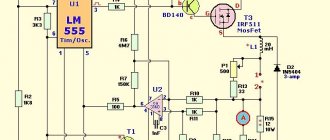
Figure 4 – Inverter voltage stabilizer circuit
Read more about this topic below:
Inverter voltage stabilizers "Calm". The lineup.
Electromechanical voltage stabilizer
What is this device? Essentially, this is a transformer (voltage booster) that independently regulates the voltage on the supply loop. That is, there is no need to tighten anything if there is a need to add a few volts, as is done with relay analogues.
Currently, the scope of application of electromechanical stabilizers is quite extensive. These are not only household premises and offices; these devices are also in demand in places where high-precision electronic equipment is used. For example, in medical institutions.
Classification of stabilizers
The main division of electromechanical voltage stabilizers is based on the voltage itself. That is, they are single-phase (220 volts) and three-phase (380 volts). It is clear that the former are most often used in the private sector and in office premises, the latter in large institutions and production. Although today, when the population has the opportunity to build their own large houses, which house a huge amount of household appliances, three-phase voltage stabilizers began to be installed in them.
In terms of their design, the devices are represented by wall-mounted, floor-mounted, table-top models, and can be mounted both horizontally and vertically. That is, the manufacturers took into account all the options for a convenient location, depending on the location of the device. It should be noted that these voltage stabilizers have a very accurate voltage setting, operate without extraneous interference, have shown themselves to be excellent under short-term high overloads, and at the same time have a fairly wide range of stabilization of the voltage itself.
And the third position of separation is the power of the device. Currently, manufacturers offer a very wide range of models in this regard. Here you can find simple low-power voltage stabilizers 500 kVA, and high-power units up to 20,000 kVA. It should be noted that purely structurally, the two positions (220 and 380 volts) differ from each other in that the first option has one transformer and one brush block, while the design of the second may contain two or three transformers.
Advantages and disadvantages
Electromechanical voltage stabilizers have a wide range of advantages over other analogues:
- widest input voltage range;
- high accuracy of the output voltage indicator, virtually no distortion;
- safe operation at high short-term input voltage, regardless of whether it is 220 volts or 380;
- low sensitivity (almost complete absence) to the operating frequency makes it possible to use three-phase voltage stabilizers at industrial facilities;
- silent operation even with the highest voltage surges in the supply network.
Not without its drawbacks:
- unfortunately, this is not an electronic device, so the design of the electromechanical stabilizer contains moving elements that will have to be replaced with new ones every 5-6 years;
- Once every ten years, manufacturers recommend changing the servo drive of the brush block;
- if the voltage in the supply network drops below 180 volts, then almost all manufacturers do not guarantee its increase at the output to the stated rated value;
- single-phase analogues are not designed to work at low temperatures, so it is best to install them inside heated rooms;
- not a very high stabilization speed, of course, when compared with other models;
- Whether there is a need to classify this as a disadvantage, everyone decides for himself, but the operation of the servo drive of the electromechanical stabilizer is accompanied by a click that lasts a fraction of a second.
Ferroresonant stabilizers
Ferroresonant rectifiers are not equipped with a built-in voltmeter, making it difficult to measure the output voltage of the network. You won't be able to adjust the voltage yourself. Ferroresonance type stabilizers partially distort real readings, the error is up to 12%.
Those who use such devices for a long time must remember that they are capable of emitting a magnetic field, which can disrupt the proper functioning of household electrical appliances. Stabilizers of this class are configured at the factory; they do not require any additional settings at home.
Tips for choosing a stabilizer
When choosing, consider the following factors:
- Stabilizer model based on the number of network phases. If 1-phase devices operate in your three-phase network, then to protect against voltage surges it is better to use three separate single-phase stabilizers.
- Device power. When determining this parameter, you need to take into account that some devices have asynchronous motors, which have high starting currents.
- Precision stabilization to protect household devices, its performance.
- Availability of auxiliary functions.
- Operating conditions of the device.
- When choosing a device, it is necessary to take into account the wiring diagram of the power circuit.
Source
ELECTROMECHANICAL STABILIZERS
The basis of the design of this household stabilizer is an autotransformer. Voltage regulation occurs automatically: the current collector unit moves along the winding of the autotransformer, thereby changing the transformation ratio. This way the output voltage is maintained within the standard value.
Advantages:
- the most suitable power mode for household appliances;
- high stabilization accuracy (permissible deviations from the standard value - 2-3%);
- smooth adjustment;
- exclusion of self-influences that distort the sinusoidal voltage waveform;
- relatively quiet operation of the moving current collection unit.
Flaws:
- impossibility of use at high humidity, dust, and subzero temperatures;
- relatively low adjustment limits;
- low adjustment speed;
- wear of moving parts;
- the need for periodic preventive maintenance to prevent jamming of the movable current collecting element, care for brush units.
Ferromagnetic stabilizers.
Such devices were widely used in homes in the past to power refrigerators, tube televisions and receivers. The devices are simple and their cost is low. However, their use is currently limited, as they have a number of significant disadvantages:
- large weight and dimensions;
- high noise level;
- small adjustment limits;
- distortion of the sinusoidal voltage waveform;
- generation of electrical interference into the network;
- limited load capacity limits (minimum load is at least 20% of the nominal value, and overload is not allowed).
Classification
There are several types of on-load tap-changers, differing in the following characteristics:
- a type of current-limiting element - with reactors or resistors;
- presence or absence of a contactor;
- number of phases – single-phase and three-phase;
- type of current switching.
Explanation of marking for on-load tap-changer type UBB...
Depending on the method of current switching, there are the following types of devices:
- the arc breaks in a volume filled with transformer oil - the device involves the use of arc extinguishing contacts that do not require the use of special elements to extinguish the arc;
- the arc breaks in a rarefied space - it is suggested to use vacuum arc extinguishing chambers produced industrially;
- shutdown is carried out using thyristors, in an arcless manner;
- combined methods - with a combination of different types of switching.
To ensure the safety and functionality of the on-load tap-changers, they are equipped with automatic monitoring elements and voltage regulators.
In addition to the above devices, special booster transformers can be used to change the voltage characteristics in powerful units. This equipment is connected in series and used together with the main unit as an auxiliary unit. But this method has not been widely used due to the high cost and high complexity of the circuit.
Types of transformers and operating principles
The operating principle of the structural device, power indicators and required nuances differ depending on how many kV the equipment operates at. The requirements must be observed; even the smallest errors lead to a change in ferroresonance stability.
Operating at 110 kilovolts
The ferroresonance phenomena that arise during the operation of 110 kV networks are caused by the initiation of grounding to reduce currents. There are resonant oscillations associated with:
- harmonic and subharmonic - appears between condensates with certain capacitance values and inductance of transformers;
- subharmonic in partial phase modes - appears as a result of penetration through between phase lines when voltage is applied to a disconnected phase;
- harmonic with incomplete phase - present when the device operates with grounding and interacts with the inductance in a nonlinear manner.
With a zero channel, resonance phenomena do not occur, but if a certain section changes the neutral, then this state is possible. Disconnection leads to damage to structural parts. The resistance of the primary winding creates a resonance at a frequency of 16 Hertz, as a result the energy flow is transferred through the interphase conductors.
Anti-resonance voltage transformers designed for 220, 330 and 500 kilovolts
For equipment that operates at 220, 330 and 500 kilovolts, ferroresonances with capacitors that are responsible for high-voltage shifts pose a significant problem. The capacitance is significant, and when the circuit is turned off, the voltage goes to the transformer (it is divided between the busbars and capacitors). The principle of operation is to ensure:
- linearization of magnetic wire;
- increasing the technical characteristics of the magnetic circuit;
- increase in adhesion;
- reduction in inductance characteristics;
- reduction of losses in the primary winding.
The choice of specific techniques and operating principles for such a transformer is determined by the typology of the equipment. Sometimes the best option is to choose to reduce the resonance subharmonic and at the same time reduce some of the device's performance parameters.
Transformers type: NAMI-10, NAMI-10-95, NAMI-10-95 UHL2
NAMI-10 is the first transformer used to reduce resonance. Decoding NAMI literally means that the transformer is of the type operating with voltage (N), anti-resonance (A), oil, but in a particular case there is a natural circulation of oil and air flows (M), insulation control (I). A vehicle of this type is a design of two three-winding vehicles.
NAMI-10-95 is a device operating in electrical networks with a frequency of 50 Hertz. Three-phase, designed to work with measuring systems, automatic devices, alarms. The voltage of the primary winding is 10 or 6 kV, the secondary - 0.1. The grounding is assembled from structural steel. It is oil-based, the windings with magnetic cores are placed in a vessel.
NAMI-10-95 UHL2, in addition to its main purpose (signal transmission to control, measurement or protection equipment, can be used to isolate from the maximum voltage levels of electrical appliance circuits in production. In total, two secondary windings are installed, the rated voltage of each of them does not exceed 100 V.
How to choose equipment: key characteristics
The main parameters when choosing a stabilizer are the permissible input voltage range and the power of the connected equipment
Sometimes it is necessary to pay attention to the accuracy of setting output values, adjustment speed
Phasing
There are three types:
- single phase current;
- two-phase current;
- three-phase current.
To stabilize voltage in multiphase networks, the use of specialized devices is required.
Power
The power of the stabilizer must match the power of the connected load. A device operating at maximum load will fail, but a more powerful one with a low load will work reliably, while having low efficiency.
When calculating the total load of consumers, take into account the fact that the equipment is not always turned on at the same time.
Active load
Heating devices and incandescent lamps are characterized by active power consumption, which, when calculated, fully corresponds to the total power. Such devices produce heat and light. They do not contain inductance or capacitance. A resistive load converts electrical energy into light and heat.
Reactive load
Contains capacitance and inductance:
- electric motor;
- vacuum cleaner;
- food processor;
- household tool.
That is, all devices that contain electric motors. When calculating, it requires the use of a coefficient. Since the power consumption will be greater than with a reactive load.
Power reserve
When choosing power, they are guided by the fact that normal operation is ensured if there is a reserve of at least 30%. That is, if the load power is 3500 W, then the stabilizer power is at least 5000 W.
Power reserve is important when the mains voltage is low. The lower the input voltage, the more the load capacity is reduced.
Stabilized voltage range
Each device remains operational only within a narrow voltage range. The acceptable range varies depending on the type of stabilizer used. For example, electromechanical ones have 180 - 240 V, and inverter ones have 110 - 250 V.
If the voltage goes beyond the specified limits, the protection will trip and the device will shut down.
Stabilization accuracy
Stabilization accuracy is the ability of a device to maintain the output voltage within the specified parameters. Electromechanical and inverter stabilizers have the best accuracy. Relay or thyristor ones have a stepwise change in the output voltage within 5V. This change is noticeable when using certain types of lighting fixtures and is expressed in brightness jumps.
Installation method
Depending on the requirements and power, I install stabilizers in several ways:
- for the entire network;
- for separate groups of devices;
- for each consumer.
It often happens that several low-power stabilizers are more cost-effective than one powerful one. Added to this is an increase in reliability.
Availability of information display
The information display on the instrument panel is a necessary functional element that allows you to visually monitor the status of network parameters. It will show:
- input and output voltage;
- load;
- warning;
- overload;
- overheat.
Manufacturer
Equipment from leading manufacturers is reliable, but also expensive. Many, wanting to save money, purchase products from unknown manufacturers at a minimal cost, although this choice has an extremely low guarantee of proper operation. And it can even be the cause, for example, of a fire.
Ferroresonance in a voltage transformer: operating principle of a voltage stabilizer
Ferroresonant voltage stabilizers have long been actively used not only in everyday life, but also in industry. Devices of this class allow you to equalize AC voltage. The operating principle is based on the effect of electromagnetic resonance in an oscillatory circuit. Such normalizers have a lot of advantages, but also have their disadvantages.
Ferroresonance phenomena in electrical networks
The main factors that give rise to ferroresonance phenomena in electrical networks are elements of capacitive and inductive types. They are capable of forming oscillatory circuits during switching periods. This effect is especially noticeable in power type transformers, linear booster transformers, shunt circuits and similar devices that are equipped with massive windings.
This phenomenon comes in two types: resonance of currents and voltage.
Voltage ferroresonance is possible when there is inductance in the network, characterized by a nonlinear current-voltage property. This characteristic is characteristic of inductors, where the cores are made from ferromagnetic components. This is especially true for rectifiers from the NKF line. This negative phenomenon is caused by a small indicator of resistance of ohmic and inductive types in relation to power transformers.
Ferroresonance in a voltage transformer
When a voltage transformer is connected to the network, series-combined LC circuits are formed in it, which are a resonant-type circuit. When an inductive element with a nonlinear current-voltage property is connected in series to a capacitive-type element, the voltage in this zone of the circuit is characterized as active-inductive.
After a certain time period, the voltage value on the inductive element becomes peak, the magnetic circuit is energized, and the voltage on the capacitive type component continues to increase. Ferroresonance in a voltage transformer occurs when the voltage of the inductance and capacitive element becomes equal.
The rapid transition of the applied voltage from the active-inductive type to the active-capacitive type is referred to as “phase reversal”. This effect is dangerous for electrical appliances.
Ferroresonant stabilizers
Ferroresonance stabilizer
Ferroresonant rectifiers are not equipped with a built-in voltmeter, making it difficult to measure the output voltage of the network. You won't be able to adjust the voltage yourself. Ferroresonance type stabilizers partially distort real readings, the error is up to 12%.
Those who use such devices for a long time must remember that they are capable of emitting a magnetic field, which can disrupt the proper functioning of household electrical appliances. Stabilizers of this class are configured at the factory; they do not require any additional settings at home.
The influence of the stabilizer on technology
A ferroresonant voltage stabilizer, the operating principle of which is not simple, affects household appliances as follows:
- Radio receiver - signal reception sensitivity can be reduced, the output power indicator is significantly reduced.
- Music center - the output power of such equipment can be significantly reduced, erasing and recording new discs is significantly worse.
- TV – when connected to a stabilizer, you can observe a significant decrease in the quality of the picture on TV, some colors are not transmitted correctly.
The electrical circuit of modern ferroresonant type normalizers has been improved, which allows them to withstand heavy loads. Such devices can guarantee precise regulation of the mains voltage. The adjustment procedure is performed by a transformer.
Operating modes
The operating modes of stabilizers depend on a number of factors. The power indicator and the class of the device have a direct impact. The power characteristics of the device may be different; they must be selected taking into account the type of electrical equipment being connected.
The operating modes of the rectifier depend on the following types of load:
- inductive;
- active;
- capacitive
Active loading in its pure form is extremely rare. It is necessary only in those circuits where the variable value of the device has no restrictions. Capacitive loads can only be used for those rectifiers that have low power.
Operating modes
These modes most often depend on various factors. The mode is affected by the power and type of device. The power of the device can be different and it must be selected taking into account the type of connected devices that are planned to be connected for operation. The operating modes of the rectifying device depend on the following types of load:
- Inductive.
- Capacitive.
- Active.
Purely active load exists very rarely. It is required only in circuits without limiting the variable value of the device. If you need to apply a capacitive load, then you need to know that it is only used for stabilizers with low power. The response is determined by a capacitance resistance much smaller than the load.
Classification of voltage transformers
TNs are classified according to the following parameters:
- primary winding voltage (3, 6, 10 ... 750 kV)
- voltage of the main secondary winding (100 V - for single-phase, connected between phases, three-phase; 100√3 - single-phase, connected between phase and ground voltage of the additional secondary winding (100V - single-phase in a network with a grounded neutral, 100√3 - single-phase in a network with isolated neutral
- number of phases (single-phase, three-phase)
- number of windings (two-winding, three-winding)
- accuracy class (0.1 0.2 0.5 1 3 3Р 6Р)
- cooling method (dry, oil, gas-filled)
- insulation (air-paper, cast, compound, gas, oil, porcelain)
For voltages of 6 and 10 kV, cast transformer transformers filled with epoxy resin are used. These devices are installed in switchgears. They take up smaller dimensions compared to oil ones. Their advantages also include less maintenance.
High frequency stabilizer models
Compared to relay models, a high-frequency voltage stabilizer (the circuit is shown below) is more complex, and more than two diodes are used in it. A distinctive feature of devices of this type is considered to be high power.
The transformers in the circuit are designed to withstand high noise levels. As a result, these devices are able to protect any household appliance in the house. The filtering system in them is configured for various jumps. By controlling the voltage, the current value can be varied. In this case, the limiting frequency indicator will increase at the input and decrease at the output. Current conversion in this circuit is carried out in two stages.
Initially, a transistor with a filter at the input is used. At the second stage, the diode bridge is turned on. In order for the current conversion process to complete, the system requires an amplifier. It is usually installed between resistors. Thus, the temperature in the device is maintained at the proper level. Additionally, the system takes into account the power source. The use of the protection unit depends on its operation.