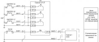
The terminals of the secondary windings (two or more) and the body of the current transformer must be combined, grounded and connected to the ground terminal of the megohmmeter. The “L” terminal of the device is connected to the terminal of the primary winding “L1” or “L2”.
The insulation resistance of the secondary windings is measured on each winding relative to the housing and the remaining windings connected to it. The “L” terminal of the megohmmeter is connected to the terminals of the winding being tested, and the “ground” terminal is connected to the terminals of the remaining windings connected to the body of the current transformer and grounded.
2. Measurement of the dielectric loss tangent tg δ of insulation
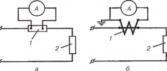
Measurement of tg δ of the main insulation is carried out at a voltage of 10 kV using a normal (direct) measuring bridge circuit. The measurement diagram for basic insulation using an AC bridge type P5026 is shown in Fig. 2.
The procedure and methods of using devices are described in the test procedure for power transformers (M1. 3).
Measurement of tg δ for all types of CTs is carried out without disconnecting the secondary circuits.
3. High voltage test
Before testing electrical equipment, the outer surface of its insulation must be cleaned of dust and dirt, except in cases where the tests are carried out using a method that does not require disconnecting the electrical equipment.
When testing electrical equipment with increased voltage with a frequency of 50 Hz, it is recommended to supply line voltage to the test installation.
Test duration means the time of application of the full test voltage established by the test standards.
When comparing measurement results, the temperature at which the measurements were taken should be taken into account and corrections made in accordance with special instructions.
When carrying out several types of insulation tests on electrical equipment, the high voltage test should be preceded by a thorough inspection and assessment of the insulation condition by other methods.
What kind of lighting do you prefer?
Built-in Chandelier
Equipment rejected during external inspection, regardless of the test results, must be replaced or repaired.
It is recommended to test current transformers with increased voltage before installing them on a stationary testing installation, except for busbar CTs, which are tested only after installation together with the busbar.
The test voltage is applied to each winding in turn. The remaining windings are connected to the housing and grounded.
When testing secondary windings and the circuits connected to them with increased voltage, it is necessary to check the admissibility of applying the test voltage to all devices.
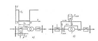
4. Removing magnetization characteristics
Magnetization characteristics are used to identify steel damage, the presence of shorted turns, and determine the suitability of current transformers based on their errors for use in a given relay protection circuit at a given load.
1.5 Main parameters and characteristics of the TT
(Figure 1.14). However, it is not possible to determine the value of Kd and enter it into the calculation formulas.
Expert opinion
It-Technology, Electrical power and electronics specialist
Ask questions to the “Specialist for modernization of energy generation systems”
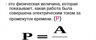
Transformation ratio of the zero-sequence current transformer Thermal resistance current I t is equal to the highest effective value of the short-circuit current for the period of time during which the CT withstands this current without heating the current-carrying parts to temperatures exceeding the permissible ones. Ask, I'm in touch!
Rated secondary current I2 nom – the value of the secondary current i2 nom when the primary current is equal to i1 nom.
Moreover, I2 nom = 1 A is allowed only for transformers
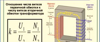
The main parameters of a CT as a functional current converter include the transformation ratio.
Turning ratio
is equal to the ratio of the number of turns of the secondary winding W2 to the number of turns of the primary winding W1.
If we divide the primary current actually flowing through winding W1 by the turn transformation ratio, we obtain the so-called primary reduced current (primary current reduced to the secondary winding).
This current is also called the secondary current of an ideal CT, i.e. such a transformer in which there are no losses (overcoming the resistance of the secondary circuit by the secondary current, radiation of electromagnetic energy, losses due to hysteresis, losses due to heating of the core by eddy currents).
The secondary current I2 of the current transformer is always less than the primary reduced one
R
Kd is the ratio of the real primary current I1 to the real secondary current I2.
Figure 1.14 The nature of the change in the KdTT coefficient depending on the multiplicity of the primary current and resistance Zn
In practice, when calculating the response currents of the measuring elements of relay protection, they use the rated transformation ratio, which is the ratio of the primary rated current of the CT to its secondary rated current
The nominal transformation ratio is indicated in the passport documentation of each CT and on a plate attached to the CT body in the form of a fraction, for example, 300/5; 4000/1; 8000/5, etc.
Expert opinion
It-Technology, Electrical power and electronics specialist
Ask questions to the “Specialist for modernization of energy generation systems”
Selection of current transformers by primary current, load and voltage | | ENERGY SAVING The L terminal of the megohmmeter is connected to the terminals of the winding being tested, and the ground terminal is connected to the terminals of the remaining windings connected to the body of the current transformer and grounded. Ask, I'm in touch!
Household network potential ratings
Exceeding or decreasing the established standard in the energy system leads to improper operation of consumers and breakdown of devices. It is especially important to maintain the required level of Unom in production schemes - here the consequences can be more severe: up to stopping the technological process. Household appliances, according to the degree of susceptibility to changes in rating from the most resistant to the most sensitive, are divided into the following groups:
- Devices with heating elements: heaters, irons and kettles. When there is excess voltage, the excess power goes into heat, protecting the device from damage.
- Electrically driven devices in the form of an asynchronous motor: fans, air conditioners, refrigerators. A short-term drop will lead to a malfunction of the equipment, but a long-term disruption of the power supply will cause breakdown of the motor windings and the need to replace the motor.
- Electronic devices: TVs, laptops and computers. Any deviation of the supply network from the norm can damage the devices, so protection is provided in their design. In case of short-term disturbances, the fuse saves, but long-term overvoltage leads to the loss of an expensive item.
- Lighting devices: fluorescent, incandescent, LED lamps. Energy-saving models are more demanding regarding the constancy of network parameters.
Checking the transformation ratio / Help / Energoboard
How to choose the right current transformer
The choice of current transformers is made based on certain values, these are: network voltage, rated primary current values, power depending on the load indicators of the consumer, transformation ratio.
Selection of current transformers by voltage
The rated voltage value (Unom) of the CT is selected greater than or equal to the value of the maximum operating voltage Uset.
Selecting a transformer based on primary current
When choosing the rated current of a transformer, they are guided by the need to meet the requirements for thermal and dynamic resistance to Is.
Selecting a current transformer by load
Calculation of the choice of current transformer based on power is made depending on the cross-section of the current-carrying conductor and the calculated power.
Calculation formula depending on the cross-section of the conductor
Load power calculation is determined by the formula
According to GOST, the CT load parameters are determined for current transformers with a rated power of 5VA and 10 VA with a lower limit set at 3.75 VA.
Selecting a current transformer by transformation ratio
Installation of a current transformer with an overestimated transformation ratio is not allowed.
In the case of an increased coefficient, it is allowed to install meters at the consumer's receiving input. On power transformers, meters can be mounted on the low voltage side.
The greatest demand is for transformers that have one transformation ratio; it does not change throughout its entire service life.
An example of transformation ratios are CT 150/5 (N-30); 600/5 (N-120); 1000/5(N-200); 100/1(N-100)
Expert opinion
It-Technology, Electrical power and electronics specialist
Ask questions to the “Specialist for modernization of energy generation systems”
Blog » Selecting measuring current transformers - main characteristics - NEOKIP online store The check can be combined with other checks - checking the secondary connection diagram, checking the effect of protection on the switch by the primary current from the load device, or checking the protection by the primary load current. Ask, I'm in touch!
Designated transformer voltage
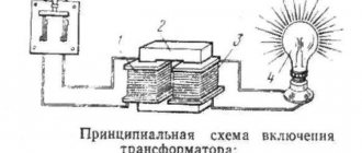
Transformare – transform, transform. This is an electrical device with two or more windings on a magnetic core, designed to transform current or voltage without changing frequency. There are the following definitions of potentials in a converting device called a transformer:
- rated primary voltage - winding 1 is designed for it;
- Unom secondary – potential at coil terminals 2, measured at idle speed of the converter and the standard value at the incoming terminals;
- the highest U nom of the transformer is the highest of the given winding voltages;
- the lowest nominal potential, respectively, the smaller of the indicators;
- average Unom – intermediate between the two previous values.
During operation, a short circuit (short circuit) sometimes occurs when one of the transformer windings is internally connected, while the second remains energized. If an event occurs during operation at rated voltage, short-circuit currents arise in the coils, 5–10 times higher than standard ones. The phenomenon is accompanied by a significant increase in the temperature of the windings, large mechanical loads act on them - the situation becomes emergency.
To prevent such circumstances, they use protection that is triggered in a split second. The rated line voltages (kV) of high-voltage transformers are given in the table.
| First winding | 3,00; 3,15 | 6,00; 6,30 | 10,00; 10,50 | 20, 0; 21,0 | 35,0; 36,5 | 110; 115 | 158: 165 | 220; 230 | 330 | 500 |
| Second wrap | 3,15; 3,3 | 6,30; 6,60 | 10,50; 11,00 | 21,0; 22,0 | 38,5 | 115; 121 | 158: 165 | 230; 242 | 330 | ― |
In order to reduce losses in power lines, the secondary windings have Unom 5–10% higher than in the corresponding lines. The exception is short-distance networks, for which the rated voltage values are set to the same for supply and consuming equipment.
Determination of secondary load currents in voltage transformer circuits
In accordance with the current distribution shown in Fig. 1 (a) İav = İo + İca, hence İa = İav – İca. If the current İav was equal in magnitude to the current İca, then the vector difference of these currents would be equal to √3 İca (see Fig. 1). By adding to the vector √3 İca the difference in the magnitudes of the currents İav and İca (see Fig. 1d), we obtain a certain vector İa, the value of which is determined by the expression: İa = √3 İca + (İav - İca) (2)
Taking İa = Ia, we can approximately determine the magnitude of the current Ia using expression (2). Similarly, the currents Ib and Ic can be determined.
Replacing in expression (2) Ia with Iph - the current in any phase, Iab with Imax - the larger of the two phase-to-phase load currents -, Ica with Imin - the smaller of these two currents -, we obtain a general expression for determining the load current of any phase of the transformer. Iph = √3 Imin + (Imax – Imin) = Imax. + 1.73*Imin – Imin or Iph = Imax. + 0.73*Imin. (3)
Meanwhile in Russia
Russia was lagging behind in development. Either the secret party cells of the first revolutionaries took away the strength of the state, or an evil fate prevented the country from keeping up with the times, the fact remains that it was not possible to catch up and overtake the West, the only high-voltage line was broken by the exclusion of Kazakhstan from the Russian Federation during the coup of the 90s .
Global energy consumption doubled every ten years during the first oil crisis. By the beginning of the 80s, the first ultra-high voltage lines were built:
- 1150 kV AC.
- 1500 kV DC.
In 1980, there were 70 power plants operating in the USSR, providing the country with 1 GW or more of power. Between 1960 and 1990, the length of Soviet state lines increased from 0.22 to 5.1 million km. At the time of the end of “perestroika,” the emphasis was on networks with a voltage class of 220 kV. Over the past years, the length of lines from 330 to 750 kV has almost doubled. Soviet politicians considered the Siberia-Ekibastuz-Ural line to be the apogee of development, where the highest potentials indicated in the text were applied.
A kilometer of line already in those days cost 10–100 thousand rubles. The numbers can increase many times over when laid under special conditions. This also applies to ultra-high voltages. Raising the voltage at high costs is acceptable; the costs of constructing power lines, converters and equipment are offset by savings on leakages. DC lines almost do not form corona discharges, so the voltage was raised to 1.5 MV, significantly reducing power losses due to the ohmic resistance of copper conductors.
Air line
In the development of any class of electrical equipment, the need to increase the transmitted power invariably arises. The most effective way is to increase the network voltage. As the current increases, energy losses by heat through the ohmic resistance of the wires increase sharply. As a result, different insulation requirements arise. If in a household circuit it is tested with current clamps with a 500 V attachment, in equipment of 6.6 or 110 kV it does not look serious.
For example, oil transformers obviously withstand higher voltages than conventional ones, because the conditions for the occurrence of an arc are deliberately created unfavorable. Consequently, in transformers, the key feature of the transition to a new class is the introduction of oil insulation. The same is said about cables, but in push-button posts the measure means something else - a transition to the category of equipment used in explosive areas.
New challenges force engineers and inventors to look for fresh technical solutions. And in each case there is a special task. It is impossible to compile a single list of voltage classes for the entire list of equipment available in industry. Obviously, there is no point in dividing household appliances by voltage classes, but the gradation remains. For example, AC power systems with voltages below 50 V and DC power systems of 120 V are considered safe and can be used in bathrooms, toilets, and kitchens.
Voltage classes
Voltage classes are quite noticeable in technology. You can find documents with similar content on the Internet:
- STO 56947007-29.130.20.104 Standard technical requirements for switchgear (complete distributed devices) of voltage classes 6-35 kV.
- GOST R 51559 Power oil transformers of voltage classes 110 and 220 kV and autotransformers with voltage of 27.5 kV for AC electric railways.
- GOST 12965 General purpose power oil transformers of voltage classes 110 and 150 kV.
- STO 56947007-29.130.10.077 Standard technical requirements for disconnectors of voltage classes 6-750 kV.
- GOST 1516.1 AC electrical equipment for voltages from 3 to 500 kV. Requirements for electrical insulation strength.
From the given names, you can see that voltage classes are rarely listed, because this concerns professionals, and they are aware of what requirements this or that equipment must satisfy. Often the grading of some authors contradicts other sources. Probably the division was made according to different factors. Let’s say that in one case design features were taken into account, in another – operational features. An outdated classification of power lines may look like this:
- Up to 1 kV – low voltage.
- Over 1 kV – high voltage.
- 330-500 and 750 kV – ultra-high voltage.
- Over 1 MV – ultra-high voltage.
Here's some other information:
- 380 V or less – low voltage.
- From 1 to 20 kV – average second voltage.
- 35 kV – average first voltage.
- 110 and 220 kV – high voltage.
- 330-500 and 750 – ultra-high voltage.
- Above 1 MV – ultra-high voltage.
It can be seen that some of the names do not match, so the voltage classes are indicated in numbers to avoid confusion. The designation usually includes phase voltage.
Line design
From the above we can conclude that the design of power transmission lines is individual for each voltage class. For example, high-voltage ceramic insulators can break a local 220V distribution pole in windy weather if hung on each line.
Low-voltage lines (see classification above) are built on single poles directly buried in the ground. Here the step voltage does not seem to be too high in the event of an accident, the only protective measure will be a local grounded lightning rod. Lines up to 20 kV differ little in design from those described. But the dimensions of the pillars, the distance between the cables, and the insulators have been increased. Lightning protection cables are not used; this is not economically justified.
Starting from 35 kV lines, the design becomes more complex; steel lightning protection cables are suspended in areas with intense thunderstorm activity. A heavy cable is used, the breaking strength of the pole is increased. The increased distance between the wires is ensured by powerful insulators mounted on special crossarms. Some poles are already reminiscent of high voltage. They consist of individual prefabricated steel sections mounted on insulating concrete slabs to block the flow of current to the ground in the event of an accident. Above 35 V, steel-aluminum cables are often used, where the load-bearing functions are assigned to a high-strength core.
On power lines with a voltage class of 110 kV, lightning protection cables are suspended along their entire length, on 35 kV lines - only in the area of substations. 330 kV lines resemble 35 in shape, but the arched poles are taller and more powerful, and much more insulators are hung to block the occurrence of an electric arc and reduce the formation of corona discharges. Lightning protection in the form of wires may not be available in windy regions where an overlap with a line causes a short circuit. The effect is also used for protection during operation of a zero-sequence relay.
Grounding conductors for high-voltage lines are usually located inside concrete supports to reduce the step voltage. In this case, the currents immediately flow underground and do not cause such destructive damage to random passers-by and animals. Starting from 500 kV, lightning protection cables are conductive and are used for communication in the form of a steel rope with one twist of aluminum wires. At these voltages, split wire is used, which sharply reduces corona losses and reduces the electromagnetic field strength. At the same time, the reactance of the line is reduced, which makes it possible to use reactors of smaller capacity and size at substations.
When a 500 kV line is split in two, the throughput increases by 21%, and in three – by 33%. This event complicates the design of insulating suspensions and reinforcement of supports. An increase in the cost of a line is not always compensated by the economic benefits received. In the Russian Federation, lines are split according to voltage classes:
- 330 kV - in two.
- 500 kV – three times.
- 750 kV – for 4 or 5 lines.
- 1150 kV – 8 lines.
The wire is divided into classes:
- Pure aluminum or steel – up to 20 kV.
- Steel-aluminum wires of the 4th group - from 35 to 110 kV.
- Steel-aluminum wires of the 3rd group - 220 kV and above.
5. Determination of the load for additional windings of voltage transformers
The load on the additional windings of voltage transformers connected in an open delta circuit is determined by the calculated consumption of the relays and devices connected to these windings. The calculation results are compared with the permissible power of the corresponding class of this type of voltage transformer. When connecting only relay equipment to additional windings, it is required to operate in accuracy class 3, and when connecting measuring instruments in accuracy class 0.2; 0.5.
Determination of load Sload. voltage transformers with different connection schemes
4.1 When connecting three single-phase voltage transformers in a star (Fig. 2)
Fig. 2 - Connection diagram of three single-phase voltage transformers in a star
The load power of the main star-connected windings of each voltage transformer is determined by the expression:
- Um.f. – phase-to-phase voltage, V;
- Iph – current in any phase, A;
Substituting the current value Iph from expression (3), we obtain
- Sload – power consumed from the voltage transformer by any of the phases of the phase-to-phase load of the secondary circuits;
- Smax.m.f and Smin.m.f. – greater and lesser power at two phase-to-phase loads.