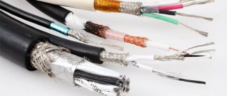
Since electricity was discovered and the first generator was built, humanity has been using various types of cable products to transport electricity. There are simply no other technologies for transmitting electric current over a distance. A cable or drive is the only electrical product that can be used to create electrification networks. These products are available in a huge range. To solve a specific problem, you need a product of the appropriate brand. If the electrical network needs to be protected from mechanical damage, then an armored cable should be used!
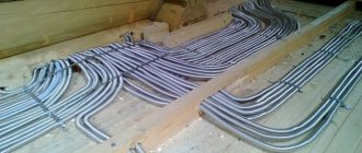
Power armored cable is a specialized electrical product, the current-carrying conductors of which are reliably protected from mechanical damage by a special additional sheath made of metal or other durable material. The range of such products is varied and each brand has its own design and technical features. Armored cable is mainly intended for laying underground power lines, but can also be used for installation in open spaces where protection from accidental damage is required.
In this article, we will look at the design, classification, scope of application and installation features of armored cables. The market for electrical products currently can offer consumers a variety of brands of such products, differing in design and labeling, as well as technical characteristics. Therefore, in order to make the right choice, you need to understand all this variety of these products. We will begin our acquaintance with the armored power cable with a description of its design and the features of all its components.
Main types and types
Before moving on to the main topic of our article, let's figure out what kind of cables there are.
Control cables usually consist of a set of cores from a couple to several dozen. Used for assembling control circuits and connecting groups of sensors and actuators. Can be shielded - this will help avoid interference and give additional strength to the product. An example of such a cable is KVVG - copper with PVC insulation. At the beginning of the marking of such cables there is usually the letter K.
KVVG
Information and signal cables. These include twisted pair and fiber optic. Optical fiber can be single-mode or multimode, depending on its purpose and design. Telephone “noodles” also belong to this class. Twisted pair cables can be supplemented with screens and protective sheaths, like other types of cable products.
Armored twisted pair cable for external installation, self-supporting
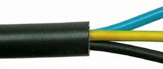
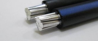
Power cables are used to connect electrical equipment to the power supply. If the first letter in the marking is A - for example, AVVG, then the cores in it are made of aluminum. If there is no letter A, for example VVG, then it is copper. The remaining letters tell us about the insulation materials and the presence of additional components. VVG stands for Vinyl-Vinyl-Bare, that is, two layers of PVC insulation and a bare core.
VVG 4×1.5
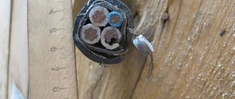
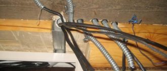
Power armored is a separate type of product designed for operation in difficult conditions in aggressive cutting or under possible mechanical stress, including in the ground. Information cables can also be protected by armor. They can be either aluminum or copper. An example is an armored copper cable VBBShV with insulation made of cross-linked polyethylene and a sheath made of pressed PVC hose, and armor made of steel tapes, you will learn more about this below.
VBBSHV with five cores
A special word needs to be said about the load-carrying geophysical cable - this is a type of armored product used for research purposes in the oil and gas industry, in marine and geological expeditions. It has another name - logging.
Logging cable
Fiber optic communication cables. How it's done
In several of my posts published more than a year ago, I raised such an interesting and somewhat exciting topic for many as backbone fiber optic communication cables, in particular, the topic of “underwater” optics. The information in these publications was incomplete, hasty and scattered, since the articles were written “on the knee” during the lunch break. Now I would like to share structured and, as far as possible, complete material on the topic of optics, with a maximum of tasty details and geek porn, which will make the soul of any techie warm. Inside are diagrams, gifs, tables and a lot of interesting text.
You are ready?
Conditional classification
Unlike the familiar twisted pair cable, which, regardless of the place of application, has approximately the same design, fiber optic communication cables can have significant differences based on the scope of application and location of installation.
The following main types of fiber optic cables for data transmission can be distinguished based on the scope of application:
- For installation inside buildings;
- for cable ducts, unarmored;
- for cable ducts, armored;
- for laying in the ground;
- suspended self-supporting;
- with cable;
- underwater.
The simplest design is for cables for laying inside buildings and unarmored sewer cables, and the most complex ones are for laying in the ground and underwater.
Cable for installation inside buildings
Optical cables for laying inside buildings are divided into distribution cables, from which the network as a whole is formed, and subscriber cables, which are used directly for laying throughout the premises to the end user. Like twisted pair, optics are laid in cable trays, cable ducts, and some brands can also be stretched along the external facades of buildings. Typically, such a cable is led to an interfloor distribution box or directly to the subscriber connection point.
The design of fiber optic cables for installation in buildings includes an optical fiber, a protective coating and a central strength element, such as a bundle of aramid threads. Optics installed indoors have special fire safety requirements, such as non-propagation of combustion and low smoke emission, so polyurethane, rather than polyethylene, is used as a shell for them. Other requirements are low cable weight, flexibility and small size. For this reason, many models have a lightweight design, sometimes with additional protection against moisture. Since the length of optics inside buildings is usually small, the signal attenuation is insignificant and does not affect data transmission. The number of optical fibers in such cables does not exceed twelve.
There is also a kind of cross between a “bulldog and a rhinoceros” - a fiber-optic cable, which additionally contains a twisted pair cable.
Unarmored sewer cable
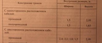
Unarmored optics are used for installation in sewers, provided that there are no external mechanical influences on them. Also, such a cable is laid in tunnels, collectors and buildings. But even in cases where there is no external influence on the cable in the sewer, it can be laid in protective polyethylene pipes, and installation is carried out either manually or using a special winch. A characteristic feature of this type of fiber optic cable is the presence of a hydrophobic filler (compound), which guarantees the ability to operate in sewer conditions and provides some protection from moisture.
Armored sewer cable
Armored fiber optic cables are used in the presence of large external loads, especially tensile loads. Reservations can be different, tape or wire, the latter is divided into one- and two-layer. Cables with tape armor are used in less aggressive conditions, for example, when laid in cable ducts, pipes, tunnels, and bridges. Tape armor is a smooth or corrugated steel tube with a thickness of 0.15-0.25 mm. Corrugation, provided that this is the only layer of cable protection, is preferable, as it protects the optical fiber from rodents and generally increases the flexibility of the cable. For more severe operating conditions, for example, when laying in the ground or on the bottom of rivers, cables with wire armor are used.
Cable for laying in the ground
For laying in the ground, optical cables with single-strand or double-strand wire armor are used. Reinforced cables with tape armor are also used, but much less frequently. The optical cable is laid in a trench or using cable layers. This process is described in more detail in my second article on this topic, which provides examples of the most common types of cable layers. If the ambient temperature is below -10 °C, the cable is preheated.
In wet soil conditions, a cable model is used, the fiber-optic part of which is enclosed in a sealed metal tube, and the armored wire is impregnated with a special water-repellent compound. This is where calculations come into play: engineers working on cable laying must not allow tensile and compressive loads to exceed the permissible limits. Otherwise, either immediately or over time, the optical fibers may be damaged, rendering the cable unusable.
Armor also affects the permissible tensile force. Fiber optic cables with double-layer armor can withstand a force of 80 kN, single-layer cables - from 7 to 20 kN, and tape armor guarantees the “survival” of the cable under a load of at least 2.7 kN.
Suspended self-supporting cable
Suspended self-supporting cables are mounted on existing supports of overhead communication lines and high-voltage power lines. This is technologically simpler than laying the cable in the ground, but there is a serious limitation during installation - the ambient temperature during work should not be lower than 15 °C. Suspended self-supporting cables have a standard round shape, which reduces wind loads on the structure, and the span between supports can reach one hundred meters or more. The design of self-supporting suspended optical cables necessarily contains a central power element - a central strength element made of fiberglass or aramid threads. Thanks to the latter, the fiber optic cable can withstand high longitudinal loads. Suspended self-supporting cables with aramid threads are used in spans of up to one kilometer
. Another advantage of aramid threads, in addition to their strength and low weight, is that aramid is by nature a dielectric, that is, cables made on its basis are safe, for example, when struck by lightning.
Depending on the structure of the core, there are several types of overhead cable:
- Cable with a profiled core - contains optical fibers or modules with these fibers - the cable is resistant to stretching and compression;
- Cable with twisted modules - contains optical fibers, loosely laid, the cable is resistant to stretching;
- Cable with one optical module - the core of this type of cable does not have power elements, since they are located in the sheath. Such cables have the disadvantage of inconvenient fiber identification. However, they have a smaller diameter and a more affordable price.
Optical cable with rope
Rope optical cables are a type of self-supporting cables that are also used for aerial installation. In such a product, the cable can be load-bearing and wound. There are also models in which the optics are built into the lightning protection cable.
Reinforcing an optical cable with a cable (profiled core) is considered a fairly effective method. The cable itself is a steel wire enclosed in a separate sheath, which in turn is connected to the cable sheath. The free space between them is filled with a hydrophobic filler. Often this design of an optical cable with a cable is called a “figure eight” because of its external similarity, although I personally have associations with overfed “noodles”. "Eights" are used for laying overhead communication lines with a span of no more than 50-70 meters. There are some restrictions in the operation of such cables, for example, a figure eight with a steel cable cannot be suspended on power lines. I hope there is no need to explain why exactly.
But cables with a winding lightning protection cable (lightning cable) can be easily mounted on high-voltage power lines, being attached to the grounding wire. Ground wire cable is used in places where there is a risk of damage to optics by wild animals or hunters. It can also be used on longer flights than a regular figure eight.
Submarine optical cable
This type of optical cable stands apart from all others, as it is laid in fundamentally different conditions. Almost all types of submarine cables are armored in one way or another, and the degree of armor depends on the bottom topography and burial depth.
The following main types of submarine cables are distinguished (by type of armor):
- Not armored;
- Single (one-step) reservation;
- Enhanced (single-layer) reservation;
- Reinforced rock (two-layer) armor;
I looked at the design of the submarine cable in detail more than a year ago in this article, so here I will give only brief information with a picture:
- Polyethylene insulation.
- Mylar coating.
- Double-layer steel wire armor.
- Aluminum waterproofing tube.
- Polycarbonate.
- Central copper or aluminum tube.
- Intramodular hydrophobic filler.
- Optical fibers.
Paradoxically, there is no direct correlation between cable armoring and burial depth, since the reinforcement protects the optics not from high pressures at depth, but from the activities of marine life, as well as nets, trawls and anchors of fishing vessels. This correlation is rather the opposite - the closer to the surface, the more anxiety, which is clearly visible in the table below:
Table of types and characteristics of submarine cables depending on laying depth
Production
Now that we have become acquainted with the most common types of fiber optic cables, we can talk about the production process of this entire zoo.
We all know about fiber optic cables, many of us have dealt with them personally (as subscribers and as installers), but as is clear from the information above, fiber optic, especially trunk, cables can be seriously different from what you dealt with in the past. indoors. Since laying a fiber optic backbone requires thousands of kilometers of cable, entire factories are engaged in their production.
Manufacturing of fiber optic thread
It all starts with the production of the main element - the fiber optic thread. This miracle is produced at specialized enterprises. One of the technologies for producing optical filament is its vertical drawing. And this happens as follows:
- At a height of several tens of meters, two tanks are installed in a special shaft: one with glass, the second, lower down the shaft, with a special polymer primary coating material.
- A glass thread is pulled from the precision feed unit of the workpiece or, more simply, the first reservoir with liquid glass.
- Below, the thread passes through a fiber optic diameter sensor, which is responsible for monitoring the diameter of the product.
- After quality control, the thread is coated with a primary polymer coating from a second reservoir.
- After going through the coating procedure, the thread is sent to another oven, in which the polymer is fixed.
- The optical fiber thread is stretched for another N-meters, depending on the technology, cooled and supplied to a precision winder; in other words, it is wound onto a reel, which is then transported as a workpiece to the cable production site.
The most common fiber optic cable sizes are:
- With a core of 8.3 microns and a shell of 125 microns;
- With a core of 62.5 microns and a shell of 125 microns;
- With a core of 50 microns and a shell of 125 microns;
- With a core of 100 microns and a shell of 145 microns.
It is not easy or almost impossible to solder optics with a core diameter of 8.3 microns in the field without high-precision equipment or installing concentrators.
Control of the diameter of the light guide is of great importance. It is this part of the installation that is responsible for one of the main parameters at all stages of thread production - the constant diameter of the final product (standard - 125 microns). Due to the difficulties in welding threads of any diameter, they strive to make them as long as possible. The linear footage of the fiber optic “blank” on a reel can reach tens of kilometers
(yes, exactly kilometers) and more, depending on the customer’s requirements.
Already at the enterprise itself, although this can be done at a glass factory, it all depends on the production cycle; for convenience, a colorless thread with a polymer coating can be rewound onto another bobbin, in the process painting it in its own bright color, by analogy with the familiar twisted pair cable. For what? For the glory of sat... for quickly distinguishing channels when, for example, repairing or welding cables.
Cable making
Now we have the heart of our product - the fiber optic thread. What's next? Next, let's look at the cross-sectional diagram of such an average underwater (yes, I like them the most) cable:
At the factory, the resulting optical filaments are launched into machines, which together form an entire conveyor for the production of one type of cable. At the first stage of production of unarmored models, the threads are woven into bundles, which ultimately constitute the “optical core”. The number of threads in the cable may vary, depending on the declared bandwidth. The bundles, in turn, are wound into a “cable” using special equipment, which, depending on its design and purpose. This equipment can also cover the resulting “cable” with a waterproofing material to prevent moisture from entering and fading of the optics in the future (called “in-module hydrophobic filler” in the diagram).
This is how the process of twisting bundles assembled together into a cable takes place at the Perm fiber optic cable plant:
After the required number of optical fiber bundles have been collected into the “cable,” they are filled with polymer or placed in a metal or copper tube. Here, at first glance, it seems that there are no pitfalls and there cannot be, but since the manufacturer strives to minimize the number of connections and seams, everything turns out to be not entirely simple. Let's look at one specific example.
To create a tube-body, shown in the diagram above as a “central tube,” a huge-length strip of the material we need (steel or copper) can be used. The tape is used so as not to have to deal with all the obvious rolling and welding around the entire circumference of the joint that we are familiar with. Agree, then the cable would have too many “weak” points in the design.
So here it is. The metal strip blank passes through a special machine that tensions it and has a dozen or two rollers that perfectly align it. Once the sliver is aligned, it is fed to another machine where it meets our fiber optic strand bundle. An automatic machine on a conveyor bends the tape around the stretched optical fiber, creating a perfectly shaped tube.
This entire, still fragile, structure is pulled further along the conveyor to a high-precision electric welding machine, which at high speed welds the edges of the tape, turning it into a monolithic tube into which a fiber-optic cable is already laid. Depending on those. process, the whole thing can be filled with a hydrophobic filler. Or don’t flood it, it all depends on the cable model.
In general, everything became more or less clear with production. Different brands of fiber optics, primarily trunk cables, may have some design differences, for example, in the number of cores. Here the engineers did not invent a bicycle and simply combine several smaller cables into one large one, that is, such a backbone cable will have not one, but, for example, five tubes with optical fiber inside, which, in turn, are also filled with polyethylene insulation and, when necessary, reinforced. Such cables are called multi-module
.
One of the cross-sectional models of a multi-module cable
Multi-module cables, which are mostly used for long highways, have another mandatory design feature in the form of a core, or as it is also called, a central power element. The CSE is used as a “frame” around which tubes with fiber optic cores are grouped.
By the way, Perm, the production process of which is presented in the gifs above, with its volumes of up to 4.5 thousand kilometers of cable per year, is a dwarf compared to the plant of the same infrastructure giant Alcatel, which can produce several thousand kilometers
fiber optic cable in one piece, which is immediately loaded onto the cable-laying vessel.
A steel tube is the least radical option for armoring optics. For non-aggressive operating and installation conditions, ordinary insulating polyethylene is often used. However, this does not negate the fact that after such a cable is manufactured, it can be “wrapped” in an armor winding made of aluminum or steel wire or cables.
Reservation of cable with polyethylene insulation at the same Perm plant
Conclusion
As you can understand from the material above, the main difference between different types of fiber optic cable is their “winding”, that is, what the fragile glass strands are packaged in, depending on the application and the environment in which the cable will be laid. If you liked this material, then feel free to ask questions in the comments, based on which I will try to prepare another article on this topic.
Thank you for your attention.
Marking of cables with a layer of armor
Protected products often have fairly long markings. To learn how to recognize brands of armored cables, you need to figure out what the letters in the markings mean, for this we will look at the example of several brands.
For armored cable AVBbShv the marking means:
- A - aluminum conductors;
- B - vinyl internal insulation;
- B - armored;
- b - without a pillow;
- Shv - outer sheath in the form of a pressed PVC hose.
VBBShvng, similar to it, stands for this:
- there is no letter “A” at the beginning, which means the wires are made of copper;
- B - vinyl internal insulation;
- B - armored;
- b - without a pillow;
- Shv - outer sheath in the form of a pressed PVC hose.
- ng - does not spread fire.
The third brand TPPepB is an armored telephone, which stands for:
- T - speaks about the purpose - “Telephone”;
- P - polyethylene insulation;
- P - polyethylene insulation;
- ep - screen made of aluminum polymer tape;
- B - armor made of two table bands.
Plastic compound
This material can be identified by the designation on the cable.
- If the aluminum drive is designated by the letter <<В>>, then the presented product has plastic insulation.
- It is inexpensive, but insulates the cable well, withstanding temperatures up to 200 C.
- It is used in places requiring an increased level of fire safety.
Design
We’ve sorted out the approximate decoding of the markings, now let’s move on to considering the general design of armored cables. It consists of:
- A conductor made of aluminum or copper.
- A layer of insulation over the core, usually PVC, polyethylene or impregnated paper.
- Next comes a screen made of copper wires or various conductive tapes, for example, metal or conductive cardboard and paper.
- On top of the screen is another layer of insulation.
- Then comes a layer of armor, usually made in the form of tapes, then the top tape is applied so as to overlap the joints of the turns of the bottom tape. Tapes like a spiral on a cable.
- may in the center of the cable ; it can be a steel rope or a fiberglass rod, coated or uncoated. It plays a load-bearing role and relieves mechanical stress from the cores.
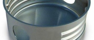
A special end coupling for an armored cable is installed at the end - it is needed to ensure that the layers of insulation and protection of the cable remain intact and safe, and the cores are separated from each other and reliably insulated.
End coupling, on the left you can see the grounding conductor for the armor, the conductors are separated and insulated, insulators are put on them
To connect building lengths of armored cables or connections during repair work in case of damage, they are also made in couplings, which are usually filled with bitumen or other dielectric solutions. More specifically, this point depends on what voltage the cable is designed for; the higher the voltage, for example 6-10 kV distribution networks, the more stringent the requirements for connections and insulation. At high voltages, the presence of air in the connection can be detrimental, as it ionizes, resulting in the development of discharges.
Advantages and disadvantages
The main and main advantage of the cable is its strength, despite the enormous loads (electrical, mechanical). This is not the only positive point on the list of advantages; it should also be noted that the cable with armor:
- it is not damaged in conditions of high humidity, it is not afraid of corrosion;
- calmly withstands high and low temperatures;
- in use for 30-50 years;
- easy to install;
- the money invested on the purchase of a cable will be justified, because it does not break and does not require frequent repairs;
- A rich assortment allows you to select the armored cable that is needed to perform a specific task.
Despite the impressive list of advantages, you should pay attention to the disadvantages. The armored cable is completely inflexible. If it is necessary to conduct electric current over many kilometers, then this indicator is insignificant. If flexibility is important, then you should choose an armored cable that is protected by a single steel spiral.
Main settings
When choosing products, you should pay attention to the following parameters:
- Rated voltage. This parameter is the first thing people pay attention to, especially if you are laying a line not of 0.4 kV, but of 6, 10 or more kilovolts. It is affected by the quality and thickness of the insulation.
- The cross-section of wires and cables is an equally important parameter that determines how much power the cable can withstand.
- Availability and type of armor.
- Availability of a screen.
- Core flexibility class. It plays an important role in electrical installations in small spaces such as electrical panels.
It is worth noting that all parameters and detailed requirements are described in state standards and specifications for cable production. An example of such regulatory documents are:
- GOST 16442-80. Standard for cables VVG, AVVG, AVBbShv, VBbShv.
- GOST 22483-77. Electrical resistance of the core.
- GOST 24641-81. Aluminum and lead sheaths for power cables.
- GOST 7006-72. Protective covers of cables (variations, requirements).
- GOST 23286-78. Insulation and sheath thicknesses, voltage tests.
- GOST 31996-2012. Power cables with plastic insulation for rated voltage 0.66, 1, 3 kV.
Application area
Armored cables are used for laying lines in tunnels, shafts, and trenches. They are laid in the ground without the use of HDPE pipes or other types of protection. But it is worth noting that such protection is never superfluous. The armor layer protects against ground movements and other harmful factors.
Interesting:
The armor is designed not only to protect against damage from a shovel or other tool, but also to protect against the teeth of rodents.
Laying on the surface is possible, subject to minimal mechanical loads and stresses. Those. it must be secured and the likelihood of stretching and impact must be minimized. In everyday life, such a cable is used to bring electricity into the house, or to connect a garage, summer kitchen, outbuilding, barn and other buildings to electricity. In this case, they are laid again - in the ground.
Laying and cutting of armored cable
Cutting an armored cable is not as simple as a regular cable. The matter will not end, as always, with simply cutting off the insulation. For proper cutting, it is necessary to expose the ends of the cable and remove layers of insulation and armor to such lengths as to obtain a reliable structure suitable for installing couplings.
You will need scissors for cutting metal strips; they are also useful for thick layers of insulation, although it will yield to a mounting knife. A hacksaw for metal and pliers for removing screens and armor tapes will also be useful. Armored cables are cut with NS (sector) scissors. They are needed for cutting out defective areas and cutting off excess length from the ends.
The lengths of the cable ends after cutting can be indicated in the instructions or documentation for the couplings or special tables from the relevant literature.
Important:
Cable cutting involves the gradual removal of protective covers - layers of insulation, armor, windings, screens. Each of the steps differs in length from the end of the cable, and the edge of the cover on this step is fixed with a steel wire bandage.
The picture shows the cutting steps, and the table shows the lengths corresponding to different cable sections in mm. This is just one example, in reality it depends on the type of cable and the type of connecting or termination, but you can use these data as a guide.
| Core cross-section, sq. mm | Length, mm | |||||
| A | B | ABOUT | P | AND | G | |
| 10-35 | 295 | 125 | 35 | 20 | 115-G | 35 |
| 50-95 | 365 | 135 | 35 | 20 | 175-G | 45 |
| 120-185 | 420 | 155 | 35 | 20 | 210-G | 50 |
| 240 | 455 | 160 | 35 | 20 | 250-G | 55 |
Armored cable is cut in stages
Explanation of symbols:
- - outer protective cover.
- - armor.
- - lead sheath.
- - waist insulation.
- — phase insulation (cores).
- - veins.
- - wire bandage.
- - wire bandage.
What is an armored drive
Armored cable belongs to electrical products. Thanks to the current-carrying conductors, it is a good conductor of electricity.
The drive has a variety of types, which differ in design and operational features.
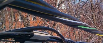
The cable is suitable for laying above-ground and underground power transmission lines.
What brands to use
AVBbShv or copper VBBbShv cables are used . They are produced in a range of sections from 2.5 to 240 sq. mm, and the number of cores can be from 1 to 5.
Appearance of AVBBShv
For high voltages of 6-10 kV or more, the following copper cables are used:
PvPg - armored high-voltage cable, insulation - cross-linked polyethylene, there is a screen, laying at the bottom of reservoirs and underground laying is possible, rated voltage depending on the specific instance is 6-10 kV. The range of core sections is 50-800 sq.mm.
Appearance PvPg
TsSPG , the rated voltage is indicated with a hyphen, for example TsSPG-10 - at 10 kV. The cores can be single-wire (they add “OZH” in the marking) and multi-wire. The insulation is impregnated paper, there is a lead sheath, a bitumen cushion and steel wire armor. Section range - 25-240 sq. mm.
Appearance of the CSPG
With aluminum cores:
AABL - armored, rated voltage 1-10 kV. Indicated in the index after the marking, i.e. AABL-6 - 6 kV cable. The cores are single-wire or multi-wire. Paper insulation, a layer of belt insulation made of semiconducting paper, then a layer of aluminum shell, armor made of two steel tapes. Section range 50-240 mm. It cannot be used for laying in a vertical position, but there is a version with non-drip impregnation for these purposes - TSAAB-10. Installation of armored cable of this brand in the ground is more possible with low corrosive activity.
Appearance of AABL
How to properly ground armor?
The connection of cable armor to grounding busbars or grounded housings of electrical installations is carried out using uninsulated sections of flexible copper wire. Experts often call such a conductor a “leash.” The most common method of attaching a leash to armor is soldering. The contact of the grounding conductor with the “earth” bus or the body of the electrical cabinet is carried out using bolted connections. To do this, a tip of the appropriate size is pressed or soldered onto the end of the conductor.
Important!
Cable armor must be grounded at both ends. In the supply switchgear, the cable armor is connected to the protective grounding bus, and on the consumer side - to the re-grounding bus.
Selecting the cross-section of the grounding conductor
The minimum cross-section of conductors for connecting cable armor to ground can be determined from the following table.
| Cable core cross-section, mm | Ground wire cross-section, mm |
| to 10 | 6 |
| 16, 25,35 | 10 |
| 50, 70, 95, 120 | 16 |
| 150, 185, 240 | 25 |
How to lay it in the ground
We reviewed above the brands of cables for laying in the ground; many of them are also suitable for laying along the bottom of reservoirs. Let's look at the features and dangers of laying cables underground:
- Tree roots often do not pose a particular danger, but still affect the line in a negative way.
- Movement of soil, especially stones and pieces of construction waste contained in the soil.
- Possibility of damage during “excavation” of communications by other services or when digging foundations for future buildings.
Armor protects to some extent from these factors; sometimes the cable is additionally laid in a protective pipe, for example HDPE or corrugated.
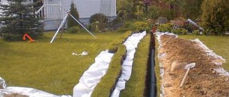
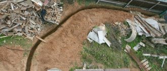
The cable in the ground should be laid without tension, freely, possibly with slight bends. A sand cushion is poured into the trench before laying the line; it will provide additional protection. The cable is covered with soil, after a short distance (20-30 cm above) a bright-colored warning tape is laid; now bright tapes are also being produced with inscriptions like “CAUTION CABLE!”
Before and after burying, check the line for short circuits, since during construction work damage to the insulating parts is possible.
Laying in the ground
The brands of armored cable presented above are suitable for placement in the soil; most of them are also applicable when installed along the bottom of reservoirs. Underground installation of products has its own dangers and nuances:
- Tree roots can negatively affect the drawn line. But usually their impact is not so significant.
- The risk of damage lies in the movement of the soil (especially the stones and construction debris contained in it).
- Disruption of wiring is possible when workers of other services dig up ready-made communications for construction or repair purposes. The cable may also be damaged during the construction of foundations for new buildings.
Armor can provide sufficient protection against such impacts. An additional reinforcement will be the laying of wires in corrugated or HDPE pipes.
It is also necessary to eliminate cable tension in the soil, with minor bends allowed. For greater protection, a sand cushion is placed at the bottom of the trench on which the wire will be laid. A bright signal tape is laid along the cable covered with earth at a distance of 20-30 cm (today you can find products with a warning label on sale).
The wiring is checked for the presence of short circuits before and after burying in the soil, since insulating layers may be affected during construction.
Laying cables under the road
If it becomes necessary to lay a section of armored cable under a road, pond, or other structures, two options are possible:
- Trench method. In this case, if the road is being laid under the road, the coating layer (asphalt, etc.) is removed. Its disadvantage is damage to the road surface, the final cost including restoration.
- The trenchless method, also known as the HDD method or the puncture method. HDD stands for “Horizontal Directional Drilling”, the only disadvantage is the need to find equipment, this can be a problem in remote regions. This method is used for laying cables, water pipes and other communications.
In any case, laying a line under the road must be agreed upon with the organization responsible for the repair and operation of this section of the road, often with the city administration.
Manufacturers
On average, all manufacturers have approximately the same price per meter of cable of the same type. There is a difference of up to 20%; delivery costs should also be taken into account, so comparing prices is not entirely correct, because logistics costs also greatly influence the final cost. However, if we talk about manufacturers, we can highlight the following products:
- JSC "Pskovkabel", Pskov;
- LLC "Rybinskkabel", Rybinsk;
- JSC "Moskabel Plant", Moscow;
- JSC ", Moscow;
- JSC "Cable", Proletarsk;
- JSC "Sibkabel", Tomsk;
- Tomskkabel LLC, Tomsk.
Source: