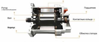
General principles of laying cable lines
Cable structures include cable tunnels, channels, ducts, blocks, shafts, floors, double floors, cable overpasses, galleries, chambers, and feeding points.
Cable structures must be separated from other rooms and adjacent cable structures by fireproof partitions and ceilings.
Using the same partitions, long tunnels should be divided into compartments no more than 150 m long when laying power and control cables and no more than 100 m long when there are oil-filled cables. In cable structures, measures must be taken to prevent process water and oils from entering them, and drainage of soil and storm water must also be ensured.
Inside cable structures, cables are laid on steel structures of various designs. Large cross-section cables (aluminum with a cross-section of 25 mm2 or more, copper with a cross-section of 16 mm2 or more) are laid directly on structures.
Power cables of smaller cross-sections and control cables are laid in trays (welded or perforated) or in boxes that are mounted on cable structures or on walls. Tray laying is more reliable and has a better appearance than open laying on structures.
Cable structures, with the exception of overpasses, wells for connecting couplings, channels and chambers, must be provided with natural or artificial ventilation.
Ventilation devices are equipped with dampers to stop air access in the event of a fire, as well as to prevent the tunnel from freezing in winter.
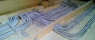
When laying cables indoors, overheating of the cables must be prevented due to the increase in ambient temperature and the influence of technological equipment (laying cables near the oil pipeline, above and below oil pipelines and pipelines with flammable liquids is not allowed). In the floor and interfloor ceilings, cables are laid in channels or pipes. It is prohibited to lay cables in ventilation ducts or openly in staircases.
Cable crossings of passages must be carried out at a height of at least 1.8 m from the floor.
2.3.122
The need for the use and scope of automatic stationary means of detecting and extinguishing fires in cable structures must be determined on the basis of departmental documents approved in the prescribed manner.
Fire hydrants must be installed in the immediate vicinity of the entrance, hatches and ventilation shafts (within a radius of no more than 25 m). For overpasses and galleries, fire hydrants must be located in such a way that the distance from any point on the axis of the overpass and gallery route to the nearest hydrant does not exceed 100 m.
Rules for laying cables in cable tunnels
Cable tunnels (and collectors in which pipelines are also laid) are recommended to be built in cities and enterprises with densely built-up areas or when the territory is heavily saturated with underground utilities, as well as in the territories of large metallurgical, engineering and other enterprises. Cable tunnels are constructed, as a rule, with the number of cables being laid from 20. Tunnels usually serve as trunk lines.
Rectangular cable tunnels are designed for double-sided and single-sided cable laying and come in pass-through and semi-pass-through designs.
With a large number of cables, tunnels and rectangular-section collectors can be three-walled (double). In table 5.6 shows the main dimensions of rectangular tunnels.
The use of semi-through tunnels is allowed in places where underground communications interfere with the construction of a through tunnel; in this case, a semi-through tunnel is accepted with a length of no more than 15 m and for cables with a voltage of no higher than 10 kV.
The width of passages in cable tunnels and collectors must be at least 1 m, however, it is allowed to reduce the width of passages to 800 mm in sections no longer than 500 mm.
Extended cable tunnels and collectors are divided along their length by fire-resistant partitions into compartments no longer than 150 m with doors installed in them. The laying of cables in collectors and tunnels is calculated taking into account the possibility of additional cable laying in an amount of at least 15%.
When cable structures are installed on both sides, control cables should be placed, if possible, on the opposite side of the power cables. When structures are located on one side, control cables should be placed under power cables and separated by a horizontal partition.
Power cables with voltages up to 1 kV should be laid under cables with voltages above 1 kV and separated by a horizontal partition. It is recommended to lay different groups of cables (working and backup voltages above 1 kV) on different shelves separated by horizontal fireproof partitions. at least 8 mm as partitions .
The use of unarmored cables with a polyethylene sheath in cable tunnels is prohibited under fire safety conditions.
Cables laid horizontally along structures are rigidly fixed at end points, at route turns, on both sides of cable bends, at connecting and end couplings and terminations. Cables laid vertically along structures and walls are secured to each cable structure. At the points of attachment between unarmored cables with a lead or aluminum sheath, metal supporting structures and a metal bracket, gaskets made of elastic material (sheet rubber, sheet polyvinyl chloride) with a thickness of at least 2 mm must be laid, protecting the sheath from mechanical damage. Unarmored cables with a plastic sheath may be secured with brackets (clamps) without gaskets.
The metal armor of cables laid in tunnels must have an anti-corrosion coating.
2.3.125
*. In places saturated with underground communications, it is allowed to construct semi-through tunnels with a height reduced in comparison with that provided in the table. 2.3.1, but not less than 1.5 m, subject to the following requirements: the voltage of the cable lines must be no higher than 10 kV; the length of the tunnel should be no more than 100 m; the remaining distances must correspond to those given in the table. 2.3.1; There should be exits or hatches at the ends of the tunnel.
* Agreed with the Central Committee of the Trade Union of Power Plant and Electrical Industry Workers.
Rules for laying cables in channels
Cable laying in cable ducts is widely used. Cable ducts are made as standard from prefabricated reinforced concrete elements or from monolithic reinforced concrete (Fig. 5.7). In industrial premises, channels are covered with slabs at floor level.
When passing outside buildings in unprotected areas, the channels are laid underground at a depth of at least 300 mm, depending on the loads that may occur on the route.
If the territory is protected, then semi-underground channels with natural or artificial ventilation are used. But such channels should not interfere with transport communications and should not be combined with the general layout of the enterprise territory, since the level of overlap of such channels rises above the planning mark by 50...250 mm.
Cables in channels are laid on structures of various designs; laying along the bottom of the channel is also possible. The number of cables in a channel can be different and depends on the diameters of the cables and the brand of the typical channel; in channels of maximum size you can put up to 50... 60 power cables. If it is necessary to lay a large number of cables, it is possible to use double or triple-walled channels, but this makes it more difficult to make branches to individual consumers.
The method of laying cables in channels allows for inspection and repair of cable lines during operation, as well as laying a new cable or replacing an existing cable without excavation work.
When laying cables in channels, they are provided with reliable protection from mechanical damage.
In table Figure 5.7 shows the main dimensions of unified cable channels (designations B, B, N in Fig. 5.7).
The main straight tray channels, their ceilings, as well as the main elements of the prefabricated channels have a length of 3 m. The prefabricated elements for the tray and prefabricated channels in places of turns and branches have a length and width based on the possibility of laying cables in them with a voltage of up to 10 kV, cross-section 3×240 mm2, with cable bending radius R = 25d.
In areas where molten metal, high-temperature liquids, or substances that can damage cable sheaths may be spilled, the construction of cable ducts is not permitted.
Cable ducts outside buildings must be covered on top of removable slabs with earth with a layer thickness of 300 mm or more. In fenced areas accessible only to maintenance personnel, for example at substations, backfilling of cable channels on top of removable slabs is prohibited.
Backfilling of power cables laid in channels is prohibited. The arrangement of cables on structures, depending on the standard sizes of the channels, can be:
- on one wall of the channel on suspensions;
- on one channel wall on shelves;
- on both walls on suspensions;
- on one wall of the channel there are hangers, on the other wall there are shelves;
- on both walls of the channel on shelves;
- at the bottom of the channel with a depth of no more than 0.9 m.
Cable channels must be calculated taking into account the possibility of additional cable laying of at least 10% of the laid ones. The horizontal clear distance between structures when they are located on both sides (passage width) must be at least 300 mm for channels with a depth of up to 600 mm and at least 400 mm for channels with a depth of 900 and 1,200 mm.
Electrical wiring is an integral part of electrical power and lighting networks of alternating and direct current with voltage up to 1 kV. Depending on the designs of the conductors, the characteristics of the premises and the environment, conductors are laid in various ways: openly on insulating supports or directly on building foundations and structures, in pipelines, on steel trays, in steel boxes, along stretched steel cables and strings, and also hidden in structural elements of buildings.
According to the accepted method of laying conductors, electrical wiring is divided into open and hidden. In industrial buildings, to generally reduce the cost of work and save metal, it is recommended to use open pipeless wiring or replace steel pipes with non-metallic ones.
For open pipeless wiring, unprotected insulated wires and unarmored cables are used, therefore the routes of such wiring in their location must ensure the safety of the wiring from possible damage. Under normal production conditions, sufficient protection is considered to be the placement of wiring indoors at a height of at least 2.0...2.5 m from the finished floor or service area and at a height of at least 3.5...6.0 m from the ground level outside the premises. If necessary, open wiring is protected from touch and mechanical damage with special boxes or pipes.
Open wiring takes up a lot of space and increases the fire hazard, worsening the appearance of buildings and premises, but in general they are much more economical than hidden wiring. Hidden electrical wiring is carried out in the structural elements of buildings, in walls, floors, ceilings, and special channels. Office, office, and residential premises are now carried out only with hidden wiring.
Selection of wire cross-section
According to statistics, most fires occur due to poor electrical wiring. But there is another factor such as overload. Before we figure this out, let's look at one more concept - electrical installation. If you turn to the dictionary or the same rules, you can find out that this concept hides the designation of a group of electrical equipment operating in one place and interconnected. All this equipment creates a certain load on the electrical wiring. If the load exceeds the current that the wire cross-section can withstand, the same overload is created. It heats up, and then the wiring lights up.
The electrical installation of the apartment consists of all household appliances powered by electricity. This necessarily includes the input node, represented by the distribution board. Inside the panel there must be automatic circuit breakers installed to protect the electrical wiring. They turn off the voltage supply if the current exceeds the rated value for a long time. But when the cross-section of the wire itself is less than the norm, it will not withstand the rated current strength at which the machine will have time to operate. The result is a fire in the wiring.
There are requirements that state that electrical wiring inside modern apartments must be made of copper cable covered with non-flammable insulation. Aluminum wires are a thing of the past, as they cannot withstand the full load of modern household electrical appliances.
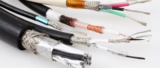
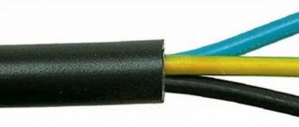
According to the standards, the following types of cable are used:
- to connect the apartment input to the distribution board, use VVG-2 with a cross-section of 6 mm2 or VVG-5 with a cross-section of 6 mm2;
- for installation of main wiring lines and connections to sockets, VVG-3 with a cross-section of 2.5 mm2 is used;
- All branches to switches and lighting devices are laid with VVG-3 wire with a cross-section of 1.5 mm2.
Figure 1. Characteristics of the VVG cable
All these requirements are specified in the rules of SNiP and PUE. The principle of calculations is based on the fact that the cross-section of the electrical wiring must withstand the rated load limited by the circuit breaker.
Requirements for the number of wire cores
Returning to the same PUE rules, in the 7th edition you can find requirements stating that all electrical wiring of a residential premises must be done with a three-core copper cable. The third core is needed for grounding.
There are two types of grounding systems, differing in the zero separation point:
- TN-S system with working zero separation (N);
- TN-CS system with protective zero separation (PE).
Be that as it may, a cable with three conductors must exit from the electrical panel into the room, that is, phase (L), zero (N) and, of course, ground (PE).
Figure 2. Types of grounding system.
The grounding wire protects a person from electric shock, as well as all household electrical appliances from burnout. When installing electrical wiring, special attention must be paid to the grounding conductor. If it breaks at a bad terminal connection, during a phase breakdown on the body of any electrical appliance, dangerous voltage will flow to all household appliances connected to the sockets.
To avoid an unexpected breakage, you cannot connect the wires with twists. For these purposes, there are special terminal blocks that differ in different wire clamping mechanisms. As a last resort, you can perform soldering. All connections must be located in junction boxes, socket boxes and panels so that they can be easily accessed. When there is old aluminum wiring in the room, it is better to replace it with new copper wiring. If this is not possible, connecting copper conductors to aluminum conductors is allowed only with special terminal blocks.
Rules for laying cables in trays
When in industrial premises the number of wires and cables laid along common routes is very large, it is advisable to use cable routing on trays. Trays are intended for:
- open laying of cables in dry, damp and hot rooms;
- rooms with a chemically active environment;
- fire hazardous premises for laying wires and cables permitted for such premises;
- cable mezzanines and basements of electrical machine rooms;
- passages behind shields and panels of control stations and transitions between them;
- technical floors of buildings and structures.
This electricity drainage system is highly flexible and greatly simplifies installation and operation. Wiring in trays provides good cooling conditions for cables, provides greater savings and reduces the cost of work compared to other types of wiring.
The trays provide free access to the cables along their entire length. If necessary, the cables can be easily removed and replaced with others; at the same time, you can change their number, section, brand, as well as route.
When using trays, it is easier to carry out wiring on complex routes; it is possible to arrange a branch on any section of the tray line route.
Trays are made of steel profiles and strips. Two types of trays are used: welded (2, 2.5 and 3 m long, 400, 200, 100 and 50 mm wide) and made of perforated strips (2 m long, 50 and 105 mm wide). Both types of trays are equipped with connecting angles and bolts for connecting the trays into a main. Individual trays and tray lines can be positioned horizontally, vertically and obliquely.
Cables on trays should be laid in one row.
Unarmored cables with a voltage of up to 1 kV with a core cross-section of up to 25 mm2 can be laid in trays in multi-layers, in bundles and single-layers without gaps. The height of cable layers laid in multilayers should be no more than 150 mm. The height (diameter) of the beam should be no more than 100 mm. The distance between bundles of power cables must be at least 20 mm; The distance between bundles of control cables, as well as power and control cables, is not standardized.
Fastening of cables laid in trays on straight sections of the route is not required when installing trays horizontally; with any other arrangement of trays, the cables are attached to the trays at intervals of no more than 2 m.
Advantages of underground wiring
Laying cables underground has a number of advantages over above-ground ones:
- Reducing the chance of network damage. If all installation standards are observed, the cable will be difficult to transfer or move, and its condition will not be affected by weather conditions and trees.
- It's easier to determine the length of the wire. If a cable is selected for underground installation, then during selection it is necessary to take into account the cross-section and length of the entire line. For an overhead cable, the weight and tension would have to be calculated to avoid overloading.
- Lower costs. To connect, you only need a forced network shutdown device, as well as small expenses for the project.
- Less risk of fire.
- Exposure to electromagnetic waves and thunderstorms is also reduced.
- Aesthetics. Since the wires are underground, the area can be used according to your preferences. The main thing is to remember where the wire is located so that there are no problems when planting trees.
Area before digging a trench Source s00.yaplakal.com
Rules for laying cables on a cable
In cases where other types of cable laying cannot be used for technological, design or economic reasons, cable laying on cables (on a steel rope) is used. Laying power cables on cables is used in networks with voltages up to 1 kV, both indoors (workshops) and outdoors. Cable wiring on cables indoors is carried out along columns along and across the building, as well as between walls, and outdoors - as a rule, between the walls of buildings.
For power lines laid on a cable, the same cables are used as for laying inside buildings and structures. Cables laid outside buildings, including under open sheds, must have a protective non-flammable outer covering.
The choice of cable is made depending on the load-bearing load.
As a supporting cable, ropes woven from galvanized steel wires and hot-rolled galvanized steel wire are used.
The distance between the anchors of the supporting cable should be no more than 100 m.
The distance between intermediate fastenings should be no more than 30 m when laying one or two cables with a cross-section of up to 70 mm2, 12 m when laying more than two cables with a cross-section of 70 mm2 and in all cases of laying cables with a cross-section of 95 mm2 or more. The distance between cable hangers should be 0.8... 1.0 m.
Anchor end structures are attached to building walls or building columns; fastening them to beams and trusses is not allowed.
2.3.126
Oil-filled low-pressure cables must be mounted on metal structures in such a way that the possibility of forming closed magnetic circuits around the cables is excluded; the distance between fastening points should be no more than 1 m.
Steel pipelines of high-pressure oil-filled cable lines can be laid on supports or suspended on hangers; the distance between supports or hangers is determined by the line design. In addition, pipelines must be fixed on fixed supports to prevent thermal deformations in the pipelines under operating conditions.
The loads taken by the supports from the weight of the pipeline should not lead to any movement or destruction of the support foundations. The number of these supports and their locations are determined by the project.
Mechanical supports and fastenings of branching devices on high-pressure lines must prevent swinging of branching pipes and the formation of closed magnetic circuits around them, and insulating gaskets must be provided in places where supports are fastened or touched.
Video description
How to warm up the wire in winter conditions is shown in the video:
With any of these methods, it is necessary to seal the ends of the cable using special couplings to prevent condensation from penetrating.
The cable needs to be warmed up only after the entire line has been fully prepared, since in winter the installation of the electrical network is strictly regulated in terms of timing. Installation of a warm wire must be carried out at a certain time:
- 60 minutes – from 0 to -10 °C;
- 40 minutes from -10 to -20 °C;
- 30 minutes – from -20 and below.
A cable for laying in the ground that has been heated should not be bent too much. After installation, it must be covered with a small layer of fluffy earth and wait until it cools, and then bury the hole.
If your budget allows, you can purchase a cold-resistant cable (CL). It is designed for low temperatures and is not damaged by severe frosts. This cable has its advantages: a good range of temperature conditions for installation (from +50 ° C to -60 ° C), as well as use without heating in frost conditions of -25 ° C.
Cold-resistant wire Source hostingkartinok.com