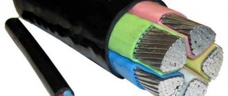
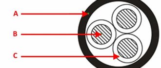
Cable design VVGng(A)
- Copper conductor, round or sector-shaped, single-wire or multi-wire, according to flexibility classes 1 and 2 (GOST R 55025-2012), nominal cross-section 1.5-1000 mm2 (GOST 31996-2012);
- Core insulation is made of PVC plastic material of low flammability, thickness from 0.6 to 3.0 mm;
- Filling internal and external spaces between twisted insulated cores of multi-core cables;
- The inner shell is made of PVC plastic material of low flammability, 1.0-2.0 mm thick;
- The outer shell is made of PVC plastic material of low flammability, thickness from 1.8 to 3.1 mm.
Table of colors used in cable markings:
White, natural or gray[/td]
| B | |
| Yellow | AND |
| Orange | ABOUT |
| Violet | F |
| Red | TO |
| Pink | R |
| Blue | WITH |
| Blue | G |
| Green | Z |
| Brown | Kch |
| Black | H |
| Green-yellow | Z-Z |
| Red-white | K-B |
| Brown-white | Kch-B |
Scope of application of VVGng(A) cable
Purpose of the cables: For laying, taking into account the volume of flammable load of the cables, in open cables. Use in stationary type installations with an alternating voltage rating of 0.66/1/3 kV with a frequency of 50 Hz or for constant voltage, 2.4 times higher than alternating voltage. For vertical, inclined and horizontal routes. Operation in areas of high humidity and in the presence of a corrosive environment is allowed. Installation in air without risk of mechanical damage. For group laying indoors. Scope of cable laying: Outdoor areas, trenches, lake/river banks, closed heated and unheated industrial premises, flooded premises, tunnels, collectors, underground structures and subways, pipes, channels.
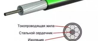
Coaxial (radio frequency) cables.
Designed for video/radio signal transmission.
An example of marking a Russian-made radio frequency cable.
RK 75-4.8-318
RK – radio frequency cable
75 – wave impedance, Ohm. Cables with a characteristic impedance of 75 Ohms are designed for transmitting a video signal, and with a characteristic impedance of 50 Ohms - for transmitting a radio signal.
4.8 – diameter of the central core insulation.
318 – number in the manufacturer’s catalog, does not carry technical information.
Imported cables.
RG-58 – cable with a characteristic impedance of 50 Ohms.
RG-59 and RG-6 – cables with a characteristic impedance of 75 Ohms.
The numbers in the marking indicate only the standard size and nothing more. RG-6 cables have an outer diameter from 4.8 to 6.6 mm, RG-59 less than 4 mm.
Thus, cables RK-75, RG-6 and RG-59 are analogues.
For indoor work, a cable in PVC insulation (PVC in English) is used, for laying outdoors in polyethylene (PE).
The most important characteristics of these cables are the attenuation coefficient and the shielding coefficient. The lower the attenuation coefficient and the higher the shielding coefficient, the better the cable. Please note that the CCA marking on imported cables indicates that the center conductor is not copper, but copper-plated steel. The characteristics of such a cable are worse than those of a similar one with a copper central core, but its cost is lower and it costs, accordingly, less. These characteristics can only be viewed in reference books. If you need to connect an antenna to a TV, the distance to which is 10 m, you do not need to look into reference books; any cable will do for this, with the exception of the cheapest Chinese samples. If the task is more complex, contact our managers, they will select a cable to suit your needs.
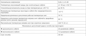
Technical characteristics of cable VVGng(A)
| Operating temperature range: | from -50 °С to +50 °С |
| Rated voltage: | 0.66/1/3 kV frequency 50 Hz |
| Peak test voltage: | 12-38 kV |
| Core flexibility class: | 1 or 2 |
| Construction length: | by customer order |
| Maximum operating temperature of the core during operation: | +70°С |
| Short circuit duration, no more: | 5 s |
| Test holding time: | 10 min |
| Insulation resistance at 20 °C: | not less than 4.8…12.0 MOhm km |
| Insulation resistance at 70 °C: | not less than 0.005 MOhm km |
| Relative air humidity at temperatures up to +35 0C: | up to 98% |
| Permissible core heating temperature: | 70°C |
| Maximum core heating temperature during overload: | 90°C |
| Maximum core heating temperature at short-circuit current: | 160°C |
| Installation temperature: | -15°C |
| Minimum bending radius for stranded: | 7.5 outer diameters |
| Warranty period: | 5 years |
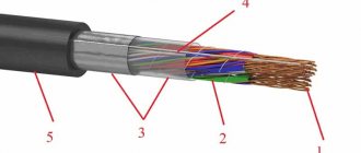
PPGng(A)-HF, PPGng-HF
Cables PPGng(A)-HF, PPGng-HF - power cables identical in design are manufactured in accordance with GOST 31996-2012 and GOST 31565-2012
Description
Cables PPGng(A)-HF and PPGng-HF are fire-resistant power cables with copper single-wire or multi-wire conductors, insulated and sheathed from halogen-free polymer compositions. Designed where a level of safety is required that exceeds the usual standards for PVC cables. The cable does not spread fire and does not emit toxins. It is used for transmission and distribution of electricity in stationary installations, with a rated alternating voltage of 0.66 and 1 kV with a frequency of up to 50 Hz.
Cable design PPGng(A)-HF, PPGng-HF:
- Current-carrying conductor - copper single-wire or multi-wire, round or sector configuration
- Insulation is made of a halogen-free polymer composition. The cores are twisted into a core. — color marking: neutral conductors are blue, grounding conductors are green-yellow.
- The inner shell is filled with a polymer composition that does not contain halogens.
- The outer shell is made of a halogen-free polymer composition.
| DESIGN | |
| Number of cores | 1 – 5 |
| Section | 1.5 – 35 mm2 |
| Conductor | copper, class 1 or 2 GOST 22483-77 (IEC 228) |
| Insulation | polymer compositions that do not contain halogens, do not propagate combustion, with low smoke and gas emissions |
| Filling | |
| Shell | |
Explanation of cable PPGng(A)-HF, PPGng-HF:
P - insulation polymer composition P - shell polymer composition G - absence of a protective cover over the shell ng - does not support combustion HF - there are no halogens in the shell and insulation
Characteristics
The cable's characteristics comply with the requirements of IEC 502, TU16.K71-304-2001.
Conditions for laying and operating cables PPGng(A)-HF, PPGng-HF:
— for laying without limiting the difference in levels along the laying route, including in vertical sections. — for installation in premises and cable structures in the absence of danger of mechanical damage during operation. — for cable lines of power supply circuits and control of electrical equipment of nuclear power plants (NPS). - for electrical wiring in office premises equipped with computer and microprocessor equipment, in crowded places.
Technical characteristics of the cable PPGng(A)-FRHF, PPGng-FRHF:
| Lower operating temperature limit | -50°С |
| Upper operating temperature limit | 50°C |
| Humidity at 35°C | 98% |
| Laying without preheating is carried out at an air temperature not lower than | -15°С |
| bending radius of a single-core cable is not less than | 10 maximum outer diameters |
| bending radius of multi-core cable not less than | 7.5 maximum outer diameters |
| Long-term permissible heating temperature during operation no more than | 70 °C |
| Smoke formation during combustion and smoldering does not lead to a decrease in light transmission in the test chamber by more than | 40%. |
| Long-term permissible heating temperature during overload no more than | 90 °C |
| Maximum heating temperature during short circuit no more | 350°С |
| Short circuit duration is no longer | 5 s |
Indicators of the corrosive activity of smoke and gas emission products during combustion and smoldering of insulation, filling and shell materials:
| Content of halogen acid gases in terms of HCl, mg/g, not more than | 5 |
| Conductivity of an aqueous solution with adsorbed smoke and gas emission products, µS/mm, no more | 10 |
| pH value (acid number), not less | 4,3 |
Size
Size and weight of cable PPGng(A)-FRHF, PPGng-FRHF with a rated voltage of 0.66 kV:
| Number and cross-section of cores, pcs. x sq. mm | Outer diameter, mm | Cable weight kg/km |
| 1×1.5 | 5.5 | 49.8 |
| 1×2.5 | 5.9 | 62.5 |
| 1×4 | 6.5 | 83.9 |
| 1×6 | 7.0 | 106 |
| 1×10 | 8.3 | 160 |
| 1×16 | 10.1 | 244 |
| 1×25 | 11.2 | 345 |
| 1×35 | 12.2 | 445 |
| 1×50 | 13.9 | 590 |
| 2×1.5 | 9.0 | 126 |
| 2×2.5 | 9.7 | 159 |
| 2×4 | 11.1 | 217 |
| 2×6 | 12.1 | 274 |
| 2×10 | 1.5 | 417 |
| 2×16 | 17.7 | 635 |
| 2×25 | 22.0 | 1048 |
| 2×35 | 24.2 | 1329 |
| 2×50 | 27.2 | 1723 |
| 3×1.5 | 9.4 | 146 |
| 3×2.5 | 10.2 | 188 |
| 3×4 | 11.6 | 261 |
| 3×6 | 12.7 | 335 |
| 3×10 | 15.3 | 518 |
| 3×16 | 18.8 | 794 |
| 3×25 | 23.2 | 1295 |
| 3×25μ+1×16μ (N) | 25.6 | 1547 |
| 3×35 | 25.6 | 1659 |
| 3×35μ+1×16μ (N) | 27.1 | 1851 |
| 3×50 | 28.8 | 2164 |
| 3×50μ+1×25μ (N) | 30.5 | 2450 |
| 3×50ms+1×25μ (PE) | 31.5 | 2396 |
| 3×50 | 28.9 | 2043 |
| 4×1.5 | 10.1 | 175 |
| 4×2.5 | 11.0 | 227 |
| 4×4 | 12.6 | 318 |
| 4×6 | 13.8 | 412 |
| 4×10 | 16.7 | 644 |
| 4×16 | 20.6 | 994 |
| 4×25 | 25.6 | 1613 |
| 4×35 | 28.0 | 2064 |
| 4×50μ (PE) | 32.0 | 2744 |
| 4×50ms (N) | 32.3 | 2656 |
| 5×1.5 | 10.8 | 203 |
| 5×2.5 | 11.9 | 267 |
| 5×4 | 13.7 | 379 |
| 5×6 | 15.0 | 497 |
| 5×10 | 18.3 | 776 |
| 5×16 | 22.7 | 1205 |
| 5×25 | 27.9 | 1944 |
| 5×35 | 30.6 | 2495 |
| 5×50μ (N,PE) | 35.5 | 3361 |
| 5×50ms (N,PE) | 35.7 | 3287 |
Size and weight of cable PPGng(A)-FRHF, PPGng-FRHF with rated voltage 1 kV:
| Number and cross-section of cores, pcs. x sq. mm | Outer diameter, mm | Cable weight kg/km |
| 1×1.5 | 5.9 | 55.6 |
| 1×2.5 | 6.3 | 68.7 |
| 1×4 | 7.1 | 94.4 |
| 1×6o | 7.6 | 118 |
| 1×10 | 8.5 | 164 |
| 1×16 | 10.3 | 249 |
| 1×25 | 11.4 | 352 |
| 1×35 | 12.4 | 451 |
| 1×50 | 14.1 | 598 |
| 1×70 | 15.6 | 811 |
| 1×95 | 17.9 | 1093 |
| 1×120 | 19.4 | 1333 |
| 1×150 | 21.6 | 1654 |
| 1×185 | 24.2 | 2084 |
| 1×240 | 27.0 | 2664 |
| 1×300 | 29.6 | 3257 |
| 1×400 | 32.7 | 4112 |
| 1×500 | 36.6 | 5277 |
| 1×630 | 40.4 | 6622 |
| 2×1.5 | 9.8 | 145 |
| 2×2.5 | 10.5 | 180 |
| 2×4 | 12.3 | 253 |
| 2×6 | 13.3 | 313 |
| 2×10 | 14.9 | 432 |
| 2×16 | 18.1 | 654 |
| 2×25 | 12.4 | 1074 |
| 2×35 | 24.6 | 1358 |
| 2×50 | 27.6 | 1756 |
| 2×70 | 30.6 | 2317 |
| 2×95 | 36.0 | 3192 |
| 2×120 | 39.0 | 3848 |
| 2×150 | 43.8 | 4826 |
| 2×185 | 48.2 | 5951 |
| 2×240 | 54.2 | 7621 |
| 3×1.5 | 10.2 | 167 |
| 3×2.5 | 11.1 | 211 |
| 3×4 | 12.9 | 301 |
| 3×6 | 14.1 | 379 |
| 3×10 | 15.8 | 535 |
| 3×16 | 19.2 | 816 |
| 3×25 | 23.9 | 1336 |
| 3×25+1×16 | 26.0 | 1582 |
| 3×35 | 26.0 | 1691 |
| 3×35+1×16 | 27.5 | 1886 |
| 3×50 | 29.2 | 2200 |
| 3×50+1×25 | 31.4 | 2527 |
| 3×50+1×25 | 31.7 | 2425 |
| 3×50 | 29.3 | 2073 |
| 3×70+1×35 | 35.1 | 3200 |
| 3×70ms | 32.7 | 2787 |
| 3×95ms+1×50μ (PE) | 39.2 | 4215 |
| 3×95 | 37.0 | 3695 |
| 3×120 | 39.6 | 4468 |
| 3×120+1×70 | 42.6 | 5274 |
| 3×150+1×70 | 46.2 | 6274 |
| 3×150 | 43.5 | 5500 |
| 3×185+1×95 | 50.2 | 7727 |
| 3×185 | 48.0 | 6742 |
| 4×1.5 | 11.0 | 200 |
| 4×2.5 | 12.0 | 255 |
| 4×4 | 14.1 | 366 |
| 4×6 | 15.2 | 467 |
| 4×10 | 17.2 | 664 |
| 4×16 | 21.1 | 1022 |
| 4×25 | 26.0 | 1648 |
| 4×35 | 28.5 | 2102 |
| 4×50 | 32.5 | 2792 |
| 4×50 | 32.5 | 2688 |
| 4×70 | 36.1 | 3571 |
| 4×95 | 40.2 | 4725 |
| 4×120 | 43.6 | 5825 |
| 4×150 | 47.4 | 7119 |
| 4×185 | 51.4 | 8673 |
| 5×1.5 | 11.9 | 232 |
| 5×2.5 | 13.0 | 301 |
| 5×4 | 15.3 | 438 |
| 5×6 | 16.6 | 558 |
| 5×10 | 18.9 | 800 |
| 5×16 | 23.2 | 1237 |
| 5×25 | 28.5 | 1990 |
| 5×35 | 31.6 | 2584 |
| 5×50 | 36.0 | 3412 |
| 5×50 | 35.9 | 3320 |
| 5×70 | 39.6 | 4401 |
| 5×95 | 44.8 | 5938 |
| 5×120 | 48.0 | 7229 |
| 5×150 | 51.8 | 8918 |
Service life 30 years.
Shelf life:
| in open areas no more | 2 years |
| under a canopy no more | 5 years |
| in enclosed spaces no more | 10 years |
← Back
General principles for marking cable products
The basic standards and principles for marking wires and cables are similar. At the same time, there is no great difficulty in decoding. The main thing is to remember a few rules.
To identify cable products, markings are used, consisting of 7 groups, including letters and numbers. The code looks like this: X ХХХ ХХХ ХХХ ХХХ ХХХ ХХХ.
Each numerical and alphabetic value is written in a strictly designated order. Stands out:
- 1 group. It indicates the material of the veins.
- 2nd group. The material used to make the armor, protection, core insulation or sheath is indicated here. The marking of the armored cable is also indicated here.
- 3rd group. Design features are indicated (these may include the possibility of using the product for installation in the ground or pipes).
- 4th group. It has a numerical indicator, which means the number of cores located in the cable. The absence of a number indicates that she lived here alone.
- 5 group. Refers to the cross-sectional area, which is expressed in mm².
- 6 group. From this characteristic you can find out the rated network voltage.
- 7 group. At the end of the marking the standard according to GOST or TU is indicated.
Decoding digital values
After the letter designations in the marking of power cables, several numbers are indicated. It will take a little effort to decrypt:
- 1 position. The operating voltage for which this type is designed is indicated here. In the absence of such a number, the cable is used for a voltage of 220 V.
- 2nd position. This indicator means how many conductors are present in the cable product.
- 3rd position. The cross section of the working core is indicated here. The second and third positions are indicated by an “x”. For example, 3 x 16 (where 3 is the number of cores, and 16 is their cross-section).
If there are cores of the same cross-section, then this is where the digital marking ends. When a “zero” core is present, it has a smaller cross-section. In this case, the “+” sign is used and the number and cross-section of the “zero” core are indicated. For example, 3 x 16 + 1 x 10.
Why is marking needed?
There are dozens of types of electrical wires and various cables on the product market, the technical characteristics of which vary. At the same time, it is impossible to select the necessary products based on appearance, since visually many of the wires are identical. Labeling can help with this.
Cable classification occurs according to a generally accepted system. At the same time, alphabetic or numerical designations are adopted for the most important features of the product. Thus, marking makes it easier to decipher the cable brand.
Wire marking
Wires and cable products have some different features; the difference is the greater flexibility of the wires and their smaller cross-section. In addition, wires are divided into stranded and single-core. You can distinguish the wire by the letters “P” in the marking. She is listed in 2nd place.
Another feature is the indication of design characteristics:
- G - the wire is flexible;
- C - used for connections;
- T - suitable for pipe laying.
Otherwise, the principle of designating cables and wires is the same.
Transcription examples
If the principle of reading abbreviations is clear, then there should be no problems finding the right products. For an example of decryption, you should pay attention to common combinations:
- APvPu2g. This marking indicates the presence of aluminum wires (A). Cross-linked polyethylene (Pv) was used to insulate the wires. The cable sheath was made from reinforced polyethylene (Pu). In addition, there is double waterproofing - this can be understood by the expression “2g”.
- APvPu. This version contains conductors made of aluminum (A), wire insulation made of cross-linked polyethylene (XLPE) and a sheath with reinforced polyethylene were used.
- KSh 50x2x0.64. This marking of communication cables is common. It shows: this is a communication cable (KS), it belongs to the mine cable (SH). The number of pairs reaches 50, 2 cores are twisted into pairs. The diameter of the conductor is 0.64 sq. mm.
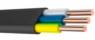
- VVGng-frls. The frls cable stands out from the rest. The abbreviation indicates the following. The conductors are made of copper (no letter A). The core insulation is made of PVC. The outer shell is made of polyvinyl chloride. The cable does not have additional armor (i.e., bare) and does not burn (this is indicated by the letters “ng”). FR - Fire Resistance, the presence of the LS index characterizes a small amount of smoke during smoldering.