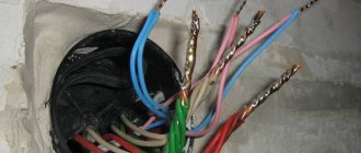
Almost every day we are faced with the same question from our customers: “how to connect an electric motor to the power supply?”
The easiest and most reliable way is to contact a proper electrician and do not skimp on this, because... Often, in an attempt to save money, they invite “Uncle Vasya” or other sympathetic “specialists” who are nearby, but in fact have little understanding of what is happening. At best, these “pros” call and ask if I’m connecting correctly. There is still a chance not to burn the engine. The qualifications of an “electrician” immediately become clear when they ask such questions that you can simply fall into a stupor (since this is exactly what electricians are taught).
For example: - why are there six contacts in the engine? — why are there only three contacts? - What are “star” and “triangle”? — why, when I connect a three-phase pump and install a float switch that breaks one phase, the engine does not stop? — how to measure the current in the windings? — what is a starter? and so on.
If your electrician asks such questions, then you need to send him back to where he came from. Otherwise, everything will end with a burnt out electric motor, loss of money, time, and expensive repairs. Let's try to understand the diagrams for connecting an electric motor to the power supply. First you need to understand that there are several popular types of AC networks:
1. Single-phase network 220V, 2. Three-phase network 220V (usually used on ships), 3. Three-phase network 220V/380V, 4. Three-phase network 380V/660V. There are also voltages of 6000V and some other rare ones, but we will not consider them.
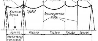
In a three-phase network there are usually 4 wires (3 phases and zero). There may also be a separate ground wire. But there are also ones without a neutral wire.
How to determine the voltage in your network? Very simple. To do this, you need to measure the voltage between phases and between zero and phase.
In 220/380 V networks, the voltage between phases (U1, U2 and U3) will be equal to 380 V, and the voltage between zero and phase (U4, U5 and U6) will be equal to 220 V. In 380/660 V networks, the voltage between any phases (U1 , U2 and U3) will be equal to 660V, and the voltage between zero and phase (U4, U5 and U6) will be equal to 380V.
Single-phase Electric Motors 220V Connection Diagrams
If the rotor begins to rotate, then the equality of the moments of these forces will be violated, since the sliding of its turns relative to the rotating magnetic fields will become different.
The invention of single-phase commutator motors, capable of withstanding a significant load, producing high torque when starting, adjusting the rotation speed and number of revolutions, has found wide application and use as an electric drive for a washing machine, vacuum cleaner and various power tools that require good power for normal operation. When connecting a three-phase electric motor to network B using a starting capacitor, you need to remember that with such a connection scheme, the motor will not work at full efficiency and will not develop maximum power.
The operating voltage of these capacitors should be 1.5 times higher than the network voltage, that is, for network B we take capacitors with an operating voltage of B and higher. This need is due to the occurrence of a voltage surge when starting and stopping the engine.
Models are available with power from 5 W to 10 kW. However, in favor of efficiency, starting characteristics are sacrificed.
Alternating current flowing through the main winding creates a periodically changing magnetic field. During operation, alternating electric fields flow around the windings: In accordance with this, the so-called starting winding is located on the stationary section of the single-phase motor.
capacitorless starting of a 3-phase motor from 220V
Speed controller
Now let's look at the motor, but not this one that is too good and working, but another one, for some reason not working and more typical (for cheap equipment):
We use a screwdriver to pry up the back cover (in Photo 3 on the right) through the slot from which the contacts peek out, and, trying not to break this piece of the board with the contacts, we pull out the cover-plug. Instead of a strip with just brushes and a bearing, we find a whole electronic device:
Moreover, the board tracks here are made by literally pouring solder into the holes of an ebonite (probably) circle. In another similar motor (Mabuchi Motor, 9V, CW) the board is more sane:
What kind of board is this, what is the microcircuit for? This is all called a low-voltage DC motor speed controller. According to the datasheet on the LA5527, this driver (speed controller) is responsible for delivering a fixed current (the current value is set by a variable resistor) to the rotor commutator brushes, almost regardless of the supply voltage. The input is 1.8-10 volts (maximum 12, nominal 9), the motor current is 1A maximum, set by a potentiometer (we see it, the little blue one, in Photo 4).
This stabilization of the output current is needed so that the engine speed and the speed of music playback do not depend on the input voltage, which can drop as the batteries run out (those tape recorders liked to work on six 1.5V batteries) or because the volume of the speakers is close to maximum.
By the way, this driver-controller is just what you need to power LEDs from batteries in a flashlight: we set the rated current of the LED (for which it is designed) with a variable resistor and power it with a battery of 3, 4.5, 6, 9 or 12 volts - without difference. Further, without reacting in any way to the decrease in battery voltage as it discharges, the LED shines with the same brightness all the way until the batteries die to zero.
Photo 4 shows that the LA5531 chip has swelled and cracked:
That's why the motor doesn't work - the mikruha burned out.
The best description of the technical characteristics of such controllers for motors is the TDA7274 datasheet. Below there are many useful graphs of the dependence of revolutions on temperature, revolutions on supply voltage, etc.
In particular, when a variable resistor rotates, the motor speed depends linearly on this rotation. That’s why the Chinese sell such “brush motor controllers with linear speed control” separately (with a large variable resistor with a handle) for 3 bucks: lots on Ebay. So, when using this motor for something (for example, as a drill or mini-drill with a collet chuck), if you want to adjust the speed, you can simply move the variable resistor outside, replacing it with a large, convenient one.
Connection diagrams
The winding with a smaller cross-section is the starting one.
This is due to the feature on which the operation of single-phase asynchronous machines is based - a rotating shaft having a rotating magnetic field, being in interaction with a pulsating magnetic field, can operate from one working phase. Afterwards it is turned off by a special device - a centrifugal switch or a start-up relay in refrigerators.
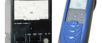
You can measure the resistance with a tester by connecting it to the terminals: at the working winding its value will be less. Inductor.
All household appliances, from a juicer to a grinder, have mechanisms of this type. Third-party substances are drawn into the device through cracks in the housing. Single-phase B motors are very popular. Thermal relay The thermal relay operates as follows: when the windings heat up to the limit set on the relay, the relay cuts off the power supply to both phases, thus preventing failure due to overload or other reason, this will prevent a fire from occurring.
To achieve this technically, the design of the electric motor provides a large number of mechanical parts and electrical circuit components: a stator with a main and additional start winding; squirrel cage rotor; boron with a group of contacts on the panel; capacitors; centrifugal switch and many other elements shown in the above picture. When connecting the device in question, several types of connections are made. That's the whole circuit for switching on a single-phase motor with a bifolar starting winding through a button. Connection diagram for a starting capacitor Since the circuit for short-term connection of a single-phase motor through a capacitor provides a button on a spring, which opens the contacts when released, this makes it possible to save money by making the starting winding wires thinner.
Application of single-phase motors
Therefore, it is important to release the start button in a timely manner.
The result is two differently directed flows with a rotation speed different from the main field. The magnetic field of the main winding maintains rotation for a long time. Options for creating a phase shift The starting coil can operate continuously. There are several such circuits; matching can be achieved using capacitors. In reality, having connected the electric motor, you need to monitor its operation and heating. When connecting the device in question, several types of connections are made. Single-phase commutator motors have the following disadvantages: The complexity of repair work, the impossibility of carrying it out independently.
Functionality check
In order to check the correctness of the assembled circuit, you need to turn on the electric motor and let it run first for one minute, and then for about 15. If the engine is hot, then the reasons may be:
- Worn, dirty or jammed bearings.
- Large capacitor capacity. turn it off and start the engine by hand; if it stops heating, reduce the capacitor capacity.
An error has occurred; The tape may not be available. Please try again later.
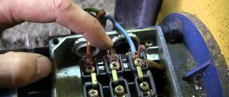
A single-phase motor can be commutator or squirrel-cage. With a commutator motor, everything is quite simple: the two wires coming out of the motor housing are plugged into a socket - the connection is made. You will have to tinker with connecting a single-phase motor with a squirrel-cage rotor. It's all about defining the conclusions. In parallel with the working winding (RO) in a single-phase motor, a starting winding (WW) is connected to create at least some kind of rotating magnetic field. A single-phase motor with four terminals has a permanently connected SW. It operates in tandem with the main one, without turning off, only the connection is made through a phase shift capacitor (Fig.a). The connection diagram for such a single-phase motor is very convenient, since all the wires are easily accessible, they can be swapped using a switch to perform reverse (Fig. a1). They can be determined without much difficulty: call with an ohmmeter and find the ringing pairs. For example, an ohmmeter determined a closed circuit of the first terminal with the second, and of the third with the fourth. This means that 1 and 2 are one winding, 3 and 4 are another. We connect the fourth wire to the second (or the first to the third, it doesn’t matter) - this is common. The beginning and the end don't matter. Next, all connections according to figure a or a1. A motor with three wires coming out is a little more difficult to deal with. In such cases, the software is connected for a short time: the engine has spun up, and it turns off, otherwise it will burn out. How does this kind of switching happen? For this purpose, a starting-protective relay was invented. Its function is not only to connect the software, but also to create its optimal shutdown time. During startup, a large current passes through the electromagnetic coil. At this moment, its core is retracted and acts on the contact that controls the software (Fig. 1 and 2). After starting, the current drops, the core is released, the starting circuit is broken. If there is an interturn short circuit in the working winding, the current is constantly high, the software remains in operation, and the engine smokes. For protection, a thermal relay with a bimetallic plate is installed, which disconnects the X3 from the network. If the engine turns on and off for a short time, then the thermal protection is triggered. The reason is either an interturn short circuit or low (high) network voltage
Pay attention to the strange, at first glance, Figure 3. This is the cover from the protective device, which shows the marking of the wires connected to it and an arrow.
Everything is clear with the markings - do not confuse the ends when connecting. But the arrow indicates the position of the relay in space. it should always face up. While still a novice electrician, I repaired a washing machine. Turned it upside down. It turned out that all I needed to do was replace the belt. I replaced it, tried to turn it on - it started working... and started smoking, the engine burned out. After some time, I learned that on an inverted relay, the contact remains closed, whereas in the normal position, under the force of gravity, after the coil is turned off, it falls down. And I just ended up at the bottom in an overturned car. To test turn it on, you just had to turn the device over so that the arrow would point upward again. How to connect a single-phase motor with unknown three wires. The resistance of the PO (X1-X3) is several times greater than the resistance of the RO (X2-X3). X3 comes out from the junction of PO and PO (see Fig. b). First, let's mark the wires so as not to get confused (the same X1, X2 and X3). We measure the resistance, for example, between X1 and X2, it turns out, say, 60 Ohms. We measured X1-X3 - 45 Ohms. Between X2 and X3 there are only 15. They wrote it all down. We look at the largest (60) - the total of all windings. 15 - working winding, 45 - starting winding. We find the wiring with which the other two show 15 and 45 Ohms. This will be our X3. You can open the engine cover and visually determine the software: it is wound with a thinner section. That's probably all!
Connection
Calculating the values of their capacitances is relatively simple: for the working one 0.75 μF per 1 kW of power, for the starting one - 2.5 times more. Its structure is slightly different from a conventional single-phase asynchronous motor.
A circuit with a working, always-on capacitor works better in nominal mode, but has mediocre starting characteristics. The operating voltage of these capacitors should be 1.5 times higher than the network voltage, that is, for network B we take capacitors with an operating voltage of B and higher.
But despite this, they are widely used in the production of household appliances. These motors have lower efficiency values.
After assembling the electromagnetic starter circuit, you should connect the power section. Its structure is slightly different from a conventional single-phase asynchronous motor. Its power can range from five to ten kilowatts. In addition to the presence of two phases, it is required that one winding be shifted relative to the other by a certain angle.
Operating principle of a commutator motor
Starting scheme: Starting is carried out by a magnetic field, which rotates the moving part of the motor. Next example.
Single-phase asynchronous electric motors Design and principle of operation The power of such a single-phase motor B can, depending on the design, range from 5 W to 10 kW. On which of them there is no difference, the direction of rotation does not depend on it. Look at the photo and you can clearly see that the wire cross-sections are different. When connecting the device in question, several types of connections are made. That is, if the auxiliary winding of a single-phase motor is starting, its connection will occur only during the start-up, and if the auxiliary winding is a capacitor, then its connection will occur through a capacitor, which remains turned on during engine operation.
Design and operating principle
Below in the figure you see a diagram of the general layout of a stepper-type electric motor. The first thing you notice is the 4 windings related to the motor stator, their location allows them to be at right angles to each other. Based on this, we can safely say that the machine has a pitch of 90 degrees.
When voltage type U1 is applied to the first winding, the rotor begins to move again 90 degrees. When voltage is supplied alternately to the remaining windings U2, U3, U4, the shaft continues to rotate until the full circle is finally completed. Then the cycle is repeated again according to a similar algorithm.
In order to change the direction of motor revolutions, it is enough to simply change the order in which pulses are supplied to certain copper windings.
How to connect a 220V asynchronous motor
Since the supply voltages for different consumers may differ from each other, there is a need to reconnect electrical equipment. Making the connection of a 220-volt asynchronous motor safe for further operation of the equipment is quite simple if you follow the proposed instructions.
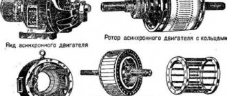
In fact, this is not an impossible task. In short, all we need is to connect the windings correctly. There are two main types of asynchronous motors: three-phase with a star-delta winding, and motors with a starting winding (single-phase). The latter are used, for example, in Soviet-designed washing machines. Their model is AVE-071-4C. Let's look at each option in turn.
The AC induction motor has a very simple design compared to other types of electrical machines. It is quite reliable, which explains its popularity. Three-phase models are connected to an alternating voltage network with a star or delta. Such electric motors also differ in operating voltage: 220–380 V, 380–660 V, 127–220 V.
Such electric motors are used in production, since three-phase voltage is most often used there. And in some cases it happens that instead of 380 V there is three-phase 220. How to connect them to the network so as not to burn the windings?
Choosing capacitors
In this case, the process is accompanied by the transformation of kinetic energy into electrical energy.
You need to connect the two contacts of the capacitor to zero and the third output of the electric motor. In distribution
What is a star and triangle in an electric motor?
The capacitance of the starting capacitor must exceed the working capacitor. The main function is taken on by the working capacitors.
If the motor has one voltage, then there will be three pins, and the remaining pins are connected and located inside the motor. That is, the beginning of the first winding is above the end of the third, the beginning of the second is the end of the first, and the beginning of the third is above the end of the second. The main thing is that, as mentioned above, their operating voltage is not less than V. To connect the ED to B using capacitors, proceed as follows: Connect the capacitors to each other as mentioned above, the connection must be parallel. With a capacitor, an additional simplified one is for a triangle circuit.
It is due to this that it becomes possible to use two voltages at once for one engine. Photo - star-delta connection diagram To the first starter, which is designated K1, an electric current is connected on one side, and the stator winding is connected to the other. That is, the beginning of the first winding is above the end of the third, the beginning of the second is the end of the first, and the beginning of the third is above the end of the second. How to connect the motor 380 to 220 via capacitors - How to connect the motor 380 220
Switching to the desired voltage
First we need to make sure that our engine has the necessary parameters. They are written on a tag attached to his side. It should indicate that one of the parameters is 220V. Next, let's look at the connection of the windings. It is worth remembering this pattern of the circuit: star - for lower voltage, triangle - for higher voltage. What does this mean?
Voltage increase
Let's say the tag says: Δ/Ỵ220/380. This means that we need a delta connection, since most often the default connection is 380 volts. How to do it? If the electric motor in the burner has a terminal box, then it is not difficult. There are jumpers there, and all you need to do is switch them to the desired position.
In this situation this does not cause any difficulties. The main thing to remember is that there is a beginning and an end to the coils. For example, let’s take as a starting point the ends that were brought out into the boron of the electric motor. This means that what is soldered is the ends. Now it’s important not to get confused.
We connect like this: we connect the beginning of one coil to the end of the other, and so on.
As you can see, the scheme is simple. Now the engine, which was connected for 380, can be connected to a 220 volt network.
Voltage reduction
Let's say the tag says: Δ/Ỵ 127/220. This means a star connection is required. Again, if there is a terminal box, then everything is fine. What if not, and our electric motor is turned on in a triangle? And if the ends are not signed, then how to connect them correctly? After all, here it is also important to know where the coil winding begins and where the end is. There are some ways to solve this problem.
First, let's move all six ends apart and use an ohmmeter to find the stator coils themselves.
Let's take adhesive tape, duct tape, whatever else we have, and mark them. It will come in handy now, and maybe someday in the future.
We take a regular battery and connect it to ends a1-a2. We connect an ohmmeter to the other two ends (c1-c2).
At the moment the contact with the battery is broken, the arrow of the device will swing to one side. Let's remember where it swung and turn on the device to ends c1-c2, without changing the polarity of the battery. Let's do it all over again.
If the arrow deviates in the other direction, then we swap the wires: we mark c1 as c2, and c2 as c1. The point is that the deviation is the same.
Now we connect the battery, observing polarity, to ends c1-c2, and the ohmmeter to a1-a2.
We ensure that the needle deflection on any reel is the same. Let's double check again. Now one bundle of wires (for example, with the number 1) will be the beginning, and the other will be the end.
We take three ends, for example, a2, b2, c2, and connect them together and isolate them. This will be a star connection. As an option, we can output them directly to the terminal block and label them. We paste the connection diagram onto the lid (or draw it with a marker).
General rules
Before switching on, be sure to check the voltage value for which the electric motor is designed - if you connect a potential difference greater than the specified one, the windings will overheat; if it is low, it will not start.
As a rule, on asynchronous machines two parameters are specified at once, less often only one:
The rating is determined together with the winding connection diagram - star or triangle. In the first case, the windings have a common point, and the phase wires are connected to the other three terminals of the coils. In the second, the end of one winding is connected to the beginning of the next in such a way that a closed circuit is formed. Some units are turned on only by a star, others by a triangle, and some can be independently connected in any of the ways; both characteristics are indicated on the nameplate of the electric motor.
For a triangle, the smaller voltage is used, and for a star, the larger of the two indicated. The difference is that three-phase motors connected in a star will have a soft start, while a delta motor can produce more power.
However, it will not be possible to achieve a full voltage shift in the stator windings. Although the rated voltage is supplied to the electric motor, the efficiency will be only 30 - 50%, which will be determined by the connection diagram of the windings of the asynchronous electric motor.
Do not turn on the electric motor without load. Since it is not designed for such a mode, the electric machine will quickly fail. Minimize idling as much as possible.
Single phase
Now let's talk about another type of asynchronous electric motors.
These are single phase AC capacitor machines. They have two windings, of which, after starting, only one of them works. Such engines have their own characteristics. Let's look at them using the example of the ABE-071-4C model. In another way, they are also called split-phase asynchronous motors. They have another auxiliary winding wound on the stator, offset relative to the main one. Starting is carried out using a phase-shifting capacitor.
Diagram of a single-phase asynchronous motor
From the diagram it can be seen that AVE electric machines differ from their three-phase counterparts, as well as from single-phase collector units.
Always carefully read what is written on the tag! The fact that three wires are output does not mean at all that it is for a 380 V connection. Just burn the good stuff!
Getting started
The first thing to do is determine where the middle of the coils is, that is, the junction. If our asynchronous device is in good condition, then this will be easier to do - by the color of the wires. You can look at the picture:
If everything is displayed like this, then there will be no problems. But most often you have to deal with units removed from the washing machine unknown when, and unknown by whom. Here, of course, it will be more difficult.
It is worth trying to call the ends using an ohmmeter. The maximum resistance is two coils connected in series. Let's mark them. Next, we look at the values that the device shows. The starting coil has more resistance than the working coil.
Now let's take the capacitor. In general, they are different on different electrical machines, but for ABE it is 6 uF, 400 volts.
If this is definitely not the case, you can take one with similar parameters, but with a voltage not lower than 350 V!
Let's pay attention: the button in the figure serves to start the ABE asynchronous electric motor when it is already connected to the 220 network! In other words, there must be two switches: one general, the other a starting one, which, after being released, would turn itself off. Otherwise, you will burn the device.
If reverse is needed, then it is done according to this scheme:
If everything is done correctly, then it will work. However, there is one catch. Not all ends can be drawn into boron. Then there will be difficulties with reverse. Unless you disassemble and take them out yourself.
Here are some points on how to connect asynchronous electrical machines to a 220 volt network. The schemes are simple, and with some effort it is quite possible to do it all with your own hands.
Source
The lineup
Now let's look at the functional components that can be connected according to the diagrams described above.
Nema 17 JK42HS34-1334-01 – the motor supplied with wires has a pitch of 1.8 degrees. Based on this, 1 full revolution is 200 steps. Main technical parameters:
- 2 phases;
- rated voltage level x 2.8 V;
- phase resistance – 2.1 Ohm;
- 22 mm – shaft length;
- 2.5 mH – inductance of each phase.
Nema 23 is a more advanced version of the stepper motor, the step is similar to the previous model - 1.8˚. Rated current - 2 amperes, operating temperature range: -20 - +85 degrees. It is equipped with a wire, the length of which is 80 cm. The phase resistance level is 2.6 Ohms, the voltage is 5.2 volts.
NEMA 23
NEMA 34 is one of the most functional series of such motors, like any other line, it includes several functional models and suitable unique components. Some modifications include encoders and other auxiliary components. Model 86BYGH1182, for example, is a bipolar type, has 2 windings and 4 outputs. Installed on printers, CNC machines and other industrial products. equipment.
Asynchronous or collector: how to distinguish
In general, you can distinguish the type of engine by a plate - a nameplate - on which its data and type are written. But this is only if it has not been repaired. After all, anything can be under the casing. So if you are not sure, it is better to determine the type yourself.
This is what a new single-phase capacitor motor looks like
How do collector motors work?
You can distinguish between asynchronous and commutator motors by their structure. The collectors must have brushes. They are located near the collector. Another mandatory attribute of this type of engine is the presence of a copper drum, divided into sections.
Such motors are produced only as single-phase ones; they are often installed in household appliances, as they allow one to obtain a large number of revolutions at the start and after acceleration. They are also convenient because they easily allow you to change the direction of rotation - you just need to change the polarity. It is also easy to organize a change in the rotation speed by changing the amplitude of the supply voltage or its cutoff angle. That is why such engines are used in most household and construction equipment.
Commutator motor structure
The disadvantages of commutator motors are high operating noise at high speeds. Remember a drill, an angle grinder, a vacuum cleaner, a washing machine, etc. The noise during their operation is decent. At low speeds, commutator motors are not so noisy (washing machine), but not all tools operate in this mode.
The second unpleasant point is that the presence of brushes and constant friction leads to the need for regular maintenance. If the current collector is not cleaned, contamination with graphite (from brushes being worn out) can cause adjacent sections in the drum to become connected and the motor simply stops working.
Asynchronous
An asynchronous motor has a stator and a rotor, and can be single or three-phase. In this article we consider connecting single-phase motors, so we will only talk about them.
Asynchronous motors are characterized by a low noise level during operation, therefore they are installed in equipment whose operating noise is critical. These are air conditioners, split systems, refrigerators.
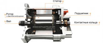
Structure of an asynchronous motor
There are two types of single-phase asynchronous motors - bifilar (with a starting winding) and capacitor. The whole difference is that in bifilar single-phase motors the starting winding works only until the motor accelerates. Afterwards it is turned off by a special device - a centrifugal switch or a start-up relay (in refrigerators). This is necessary, since after overclocking it only reduces efficiency.
Connection diagrams for single-phase asynchronous motors
With starting winding
To connect a motor with a starting winding, you will need a button in which one of the contacts opens after switching on. These opening contacts will need to be connected to the starting winding. In stores there is such a button - this is PNDS. Its middle contact closes for the holding time, and the two outer ones remain in a closed state.
Appearance of the PNVS button and the state of the contacts after the “start” button is released"
First, using measurements, we determine which winding is working and which is starting. Typically the output from the motor has three or four wires.
Consider the option with three wires. In this case, the two windings are already combined, that is, one of the wires is common. We take a tester and measure the resistance between all three pairs. The working one has the lowest resistance, the average value is the starting winding, and the highest is the common output (the resistance of two windings connected in series is measured).
If there are four pins, they ring in pairs. Find two pairs. The one with less resistance is the working one, the one with more resistance is the starting one. After this, we connect one wire from the starting and working windings, and bring out the common wire. A total of three wires remain (as in the first option):
We work further with these three wires - we use them to connect a single-phase motor.
- Connecting a single-phase motor with a starting winding via the PNVS button
connecting a single-phase motor
We connect all three wires to the button. It also has three contacts. Be sure to place the starting wire on the middle contact (which closes only during the start), the other two - on the outermost (arbitrary). We connect a power cable (from 220 V) to the extreme input contacts of the PVNS, connect the middle contact with a jumper to the working one (note! not to the common one). That's the whole circuit for switching on a single-phase motor with a starting winding (bifilar) through a button.
Condenser
When connecting a single-phase capacitor motor, there are options: there are three connection diagrams and all with capacitors. Without them, the engine hums, but does not start (if you connect it according to the diagram described above).
Connection diagrams for a single-phase capacitor motor
The first circuit - with a capacitor in the power supply circuit of the starting winding - starts well, but during operation the power it produces is far from rated, but much lower. The connection circuit with a capacitor in the connection circuit of the working winding gives the opposite effect: not very good performance at start-up, but good performance. Accordingly, the first circuit is used in devices with heavy starting (concrete mixers, for example), and with a working condenser - if good performance characteristics are needed.
Circuit with two capacitors
There is a third option for connecting a single-phase motor (asynchronous) - install both capacitors. It turns out something between the options described above. This scheme is implemented most often. It is in the picture above in the middle or in the photo below in more detail. When organizing this circuit, you also need a PNVS type button, which will connect the capacitor only during the start time, until the motor “accelerates”. Then two windings will remain connected, with the auxiliary winding through a capacitor.
Connecting a single-phase motor: circuit with two capacitors - working and starting
When implementing other circuits - with one capacitor - you will need a regular button, machine or toggle switch. Everything connects there simply.
Selection of capacitors
There is a rather complex formula by which you can calculate the required capacity accurately, but it is quite possible to get by with recommendations that are derived from many experiments:
The operating voltage of these capacitors should be 1.5 times higher than the network voltage, that is, for a 220 volt network we take capacitors with an operating voltage of 330 V and higher. To make starting easier, look for a special capacitor for the starting circuit. They have the words Start or Starting in their markings, but you can also use regular ones.
Model overview
electric motor AIR
One of the most popular are electric motors of the AIR series. There are models made on feet 1081, and models of combined design - feet + flange 2081.
Electric motors in the foot + flange design will cost about 5% more than similar ones with feet.
As a rule, manufacturers provide a warranty of 12 months.
For electric motors with a rotation height of 56-80 mm, the frame is made of aluminum. Motors with a rotation height of more than 90 mm are available in cast iron.
Models differ in power, rotation speed, height of the rotation axis, and efficiency.
The more powerful the engine, the higher its cost:
- An engine with a power of 0.18 kW can be purchased for 3 thousand rubles (electric motor AIRE 56 B2).
- A model with a power of 3 kW will cost about 10 thousand rubles (AIRE 90 LB2).
As for the rotation speed, the most common models are with frequencies of 1500 and 3000 rpm, although there are engines with other frequency values. With equal power, the cost of an engine with a speed of 1500 rpm is slightly higher than that of one with a speed of 3000 rpm.
The height of the rotation axis for motors with 1 phase varies from 56 mm to 90 mm and directly depends on the power: the more powerful the engine, the greater the height of the rotation axis, and therefore the price.
Different models have different efficiencies, typically ranging from 67% to 75%. Greater efficiency corresponds to a higher cost of the model.
You should also pay attention to engines produced by the Italian company AACO, founded in 1982:
- Thus, the AACO series 53 electric motor is designed specifically for use in gas burners. These motors can also be used in washing installations, warm air generators, and central heating systems.
- Electric motors of the 60, 63, 71 series are designed for use in water supply installations. Also, the company offers universal motors of the 110 and 110 compact series, which are distinguished by a diverse range of applications: burners, fans, pumps, lifting devices and other equipment.
You can buy motors produced by AACO for a price starting from 4,600 rubles.