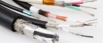
A coaxial cable (coaxial pair) is a conductor that consists of a central core and a screen. They are separated by insulating material or an air chamber, but located on the same axis. It transmits radio frequency electrical signals. The difference from a shielded wire is a uniform cross-section in the direction of one axis, the manufacture of an insulating layer from higher quality materials, and better conductor quality. All dimensional characteristics are standardized by industry standards.
This product can be thin or thick. Select it in accordance with the network parameters. The slim one has a diameter of 5 mm, it is flexible, easy to use and versatile. It connects to the computer's network adapter cards and transmits the signal over a distance of 185 m without interference or attenuation. The thin cable is equipped with copper cores.
A thick coaxial cable has less flexibility in bending; its diameter is 10 mm. Its name is often listed as "standard Ethernet", due to its use in network architecture. The copper core has a larger cross-section. The signal range is 500 m, so it can be used to connect small networks consisting of a thin analogue.
To connect to a thick type of cable, a special device is used - a transceiver, which is equipped with a vampire (piercing) tap connector - “vampire tooth” or “piercing coupler”. It is able to pass through the insulation and establish a connection to the conductor. To connect the transceiver to the network adapter, you need to connect the first wire to the AUI connector of the board. It is called the DIX connector.
As the cross-sectional area of the cable increases, the complexity of its installation increases. Thin has advantages such as ease of operation, low cost, and flexibility. Thick in this regard is inferior to its counterpart, especially when it comes to laying routes through pipes and gutters. Its advantage is the ability to transmit a signal over a greater distance.
Advantages and disadvantages
The high popularity of the cable is due to its advantages:
- slight attenuation;
- stability of operation at different signal frequencies;
- wide bandwidth;
- safety and ease of installation;
- low price, light weight, flexibility, ease of use.
Operational disadvantages include:
- lower bandwidth compared to optical fiber;
- the need for connectors, the complexity of their installation and high cost;
- the cost of installation work with a thick cable;
- more complex wiring compared to twisted pair;
- susceptibility to mechanical damage.
Areas of use
Coaxial cable is used in the following areas:
• Coaxial cable for TV or other type of broadcasting, be it digital, terrestrial or satellite; • radio-electronic equipment and radio broadcasting; • simple army equipment; • household devices; • remote control systems; • communication systems and any communication connections; • suitable for connecting computers to the Internet; • video surveillance systems; • alarm systems; • antenna-feeder systems; • communication systems; • measurement systems; • control systems; • communication equipment for mobile objects: airplanes, ships, etc.
Components
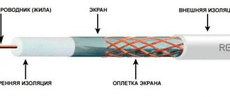
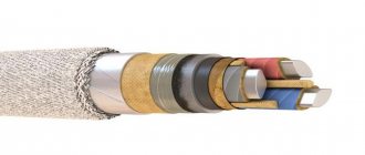
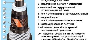
The coaxial cable includes:
- 4 – shells used as insulating and protective layers. They are made from light-stabilized polyethylene (PE), PVC, twisted fluoroplastic tape;
- 3 – the outer conductor (screen) is made in the form of a braid, foil with an outer coating of aluminum, corrugated tubes, twisted metal strips (copper, aluminum- and copper-based alloys);
- 2 – insulating layer, represented by a solid or semi-air dielectric filling, which ensures the alignment of the outer and inner conductor. It can be made of PE, foamed PE, solid fluoroplastic, fluoroplastic tape, tubular cord, washer, etc.;
- 1 – internal conductor, represented by a single straight or spiral cable, stranded conductor, tube made of copper, an alloy based on it, an aluminum alloy, copper-plated steel or aluminum, silver-plated copper.
Alignment minimizes electromagnetic energy loss due to radiation and provides protection against interference. This is due to the concentration of both components of the electromagnetic field in the space between the conductors and the impossibility of them leaving the cable. In reality, such deviations can occur, so the indicators are not ideal, and the main part of the signal is conducted through the core.
Transcript example
Design features
In the last few years, coaxial cable has begun to be replaced by modern wireless technologies that allow faster signal transmission. That is why the developers came up with alternative options. But he remained in demand in various traditional fields of activity. It is used to organize a computer network, cable television, video surveillance systems, and radio engineering complexes.
The design feature of the cable is the simplicity of the device. Inside there is a copper core that performs the main function. It must be protected by a durable shell. It is a high quality insulating material that prevents short circuits. There is a metal braid on top. The last protective layer is a shell of soft material.
Some models provide double screening. To do this, manufacturers add a thin layer of foil. This is a special technology that has appeared recently. You can buy cables in stores that have four additional layers. They provide maximum protection against strong and extraneous interference. Sometimes you can find modifications with a combination of foil and metal braid.
On the market and in stores you can find designs with additional metal mesh. It performs the important function of an additional screen. As a result, reliable protection of data transmitted over the cable is ensured.
Characteristics of coaxial cable
The main characteristics of coaxial cable include:
| probability of a collision | 10^(-9)…10^(-7); |
| frequency | more than 50 MHz (video, path length - 2 km), more than 400 MHz (radio, length - up to 50 km with an amplifier); |
| price | small compared to fiber optics; |
| interference immunity | high, including electromagnetic; |
| transferability | analog and digital signals; |
| bandwidth | wide; |
| the ability to transmit a signal over a distance without interference | 100-1000 m; |
| degree of radio emission | small. |
Linear wave impedance
The main advantage of single-ended video transmission is based on the fact that the characteristic impedance of the transmission medium does not depend on frequency (this applies mainly to medium and high frequencies), while the phase shift is proportional to frequency.
The short wires and cables used in conventional electronic equipment have negligible ohmic resistance, inductance and capacitance and do not affect the signal. However, if a signal must be transmitted over a fairly long distance, many different factors are included in the complex picture of information transfer. High-frequency signals are especially susceptible to influence. Then resistance, inductance and capacitance begin to play a significant role and significantly affect signal transmission.
From the point of view of electrodynamics, a coaxial cable can be represented as a circuit consisting of resistances (R), inductances (L), capacitors (C) and conductors (G) per unit length (Fig. 3). If the cable is of considerable length, then the combination of elements R, L and C acts as a coarse low-pass filter, which in turn affects the amplitude and phase of various components of the video signal. The higher the signal frequencies, the more they are affected by non-ideal cable properties.
Rice. 3 Introduction to coaxial cable
Each cable has a uniform structure and its own characteristic impedance (impedance), which is determined by the elements R, L, C and G per unit length.
The main advantage of single-ended video transmission is based on the fact that the characteristic impedance of the transmission medium does not depend on frequency (this applies mainly to medium and high frequencies), while the phase shift is proportional to frequency.
The amplitude and phase characteristics of a coaxial cable at low frequencies depend to a large extent on the frequency itself, but since in such cases the cable length is quite short compared to the wavelength of the signal, the effect on signal transmission is negligible.
When the characteristic impedance of the coaxial cable matches the output impedance of the video source and the input impedance of the receiving device, maximum energy transfer occurs between the source and the receiver, such a transmission line is called matched.
For high frequency signals such as video, impedance matching is of utmost importance.
For high frequency signals such as video, impedance matching is of utmost importance. When the impedance is mismatched, all or part of the video signal is reflected back to the source, affecting not only the output stage but also the image quality. Reflection of 100% of the signal occurs when the end of the cable is either short-circuited or left open (unshorted). All (100%) signal energy (voltage times current) is transmitted only when there is a match between the source, transmission media, and receiver. This is why the last element in the video signal chain always ends with a 75 ohm load, which is called a terminator (see Fig. 4).
TIP
To ensure matching between the source, transmission media and receiver, the last element in the coaxial line includes a 75 Ohm terminator.
Rice. 4. Design elements of a coaxial line
75 ohms of coaxial cable is the complex impedance determined by the voltage/current ratio at each point in the cable. This is not active resistance and therefore cannot be measured with a regular multimeter.
In television, all equipment transmitting or receiving video signals has a characteristic impedance of 75 ohms. Therefore, you need to use a coaxial cable with an impedance of 75 ohms. But manufacturers also produce other equipment, for example, with an impedance of 50 ohms (which in some cases is used for broadcast or RF equipment), but then impedance converters (passive or active) must be used between such sources and 75 ohm receivers.
75 ohms of coaxial cable is the complex impedance determined by the voltage/current ratio at each point in the cable. This is not active resistance and therefore cannot be measured with a regular multimeter.
The impedance of a coaxial cable is determined by the formula:
Characteristic impedance is independent of cable length and frequency, but depends on capacitance and inductance per unit length.
This formula means that the characteristic impedance does not depend on cable length and frequency, but depends on the capacitance and inductance per unit length. However, this is not the case if the cable length exceeds 200 meters. In this case, resistance and capacitance matter and affect the video signal.
Losses in a coaxial cable consist of two components: dielectric losses and losses in conductors. Losses in insulation depend only on its dielectric properties and do not depend on the size of the cable. Losses in conductors are strictly related to their dimensions, and to a greater extent to the cross-section of the central conductor, because the main part of the electromagnetic field propagates along the cable, greatly decreasing towards the screen. Obviously, as the cable size increases, the field concentration around the central conductor decreases, therefore, the losses also decrease.
Losses in a coaxial cable consist of two components: dielectric losses and losses in conductors.
Deviations of linear wave impedance of a cable line are expressed using return losses
.
The assessment of the line operating mode is characterized by the traveling wave coefficient (TWC)
, which characterizes the degree of coordination of the line with the load. If the BPV is equal to one, the line is fully matched to the load. In practice, such lines do not exist due to the impossibility of perfectly matching the load with the line.
The reciprocal of the traveling wave coefficient is called the standing wave coefficient
.
It is clear that cable length uniformity is essential to meeting characteristic impedance requirements. The quality of the cable depends on the accuracy and uniformity of the central core, dielectric and screen. These factors determine the values of C and L per unit length of cable. That is why special attention must be paid to cable routing and termination.
Classification
Types of coaxial cables by application:
- for aviation;
- for cable TV;
- for household appliances;
- for space technology;
- for computer networks;
- for communication.
Characteristic impedance may differ from the values indicated in the classification; for convenience, cables are divided into groups. In Russia there are five classes, and in international standards there are three. Analog audio equipment often uses conductors that are not standardized. Depending on the wave resistance there are:
- 50 Ohm - the cable is the most popular and is used in radio engineering. It transmits radio signals with maximum power and electrical strength with minimal losses;
- 75 Ohm is the second most popular conductor, used in TV systems. It is characterized by mechanical strength and low cost, and is used with low power but a significant network length. His losses are somewhat higher;
- 100 Ohm – used in pulse technology and special purposes;
- 150 Ohm – is an analogue with increased resistance;
- 200 Ohm - characterized by the highest resistance, provided only by Russian Federation standards.
Classification based on insulation diameter divides coaxial cable into groups:
- subminiature – up to 1 mm;
- miniature – 1.5-2.95 mm;
- medium-sized – 3.7-11.5 mm;
- large-sized - more than 11.5 mm.
According to the type of screen, the wire is divided into:
- from a tube made of metal;
- solid;
- with tinned braid;
- with double and multi-layer braid, additional layer;
- with single layer braid;
- standard screen;
- radiating conductor (with a specially reduced but controlled degree of shielding).
Depending on flexibility there are:
- hard;
- semi-rigid;
- flexible;
- especially flexible cable.
Installation rules
The presented wires are quite flexible, so the installation process will not be difficult. It is important to remember that the turning radius during installation cannot exceed 12 times the bending value of the cable sheath.
If the master does not follow the recommendations, then the bend will gradually destroy the integrity of the shell. The central core will push through the dielectric layer, so a short circuit will occur on the screen. It is important not to hang the cable on a nail , otherwise it will stretch under its own weight and lead to a break in the central core.
It is necessary to properly cut the ends in order to attach the connectors; the accuracy of the operation of electrical devices depends on this. You should do it this way:
- Cut the cable at right angles to the sheath.
- Insert the stripped end of the wire into a special tool to remove the insulating layer.
- Squeeze the tool, as a result the insulation will be removed and the copper core will be exposed.
- Clamp the cable well and turn it several times.
- Make a few more turns using the ring without releasing the tool.
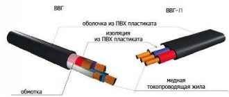
You might be interested in VVG cable: decoding of abbreviations and types of markings
After this procedure, the master receives a completely stripped cable, which is ready for further connection.
The sheath protects against moisture penetration into the copper wire and prevents various external damages during the entire period of operation. The cable should never be laid underground or in damp places. Water seeps into the protective shell, causing its gradual destruction, oxidation and short circuit of the central rod. But it can be used on the surface with low humidity levels, as well as in rainy weather.
To prevent moisture from penetrating inside, you need to carefully treat the joints. Silicone sealants are used for this. Electrical tape and plasticine are not proven methods of protection. You can also buy connectors that are resistant to the negative effects of moisture. Connections made by soldering can change the level of characteristic impedance.
What it is?
The coaxial electrical wire is a single cord made of copper, insulated with foam and surrounded by a special metal screen, covered with plastic protection on top. Thanks to this protection, the cable is high-frequency and transmits a wide range of waves.
There are two types of this cable. The first RG-58/U has a diameter of only half a centimeter, and due to its increased flexibility, its throughput is up to 10 megabits per second.
Thick coaxial cord has increased rigidity. Two categories RG-11 and RG-8 will provide resistance of 75 and 50 Ohms respectively.
Young engineers no longer saw the period when coaxial cables were the basis of all network equipment in the country. Previously, they were used in many industries, because some of their characteristics are higher than those of twisted pair. Due to the emergence of twisted pair cables, this type of cable is slowly being forced out of use: it differs in the speed of information transfer, practicality in installation and maintenance.
However, coaxial cable still has a niche in satellite equipment and telecommunications devices.
Installation Guide
RF coaxial cable is widely used to transmit a signal from a transmitter or to a receiver. Although it is very easy to install, certain conditions must be met for it to last long. This is especially important because it is often installed outdoors and must withstand harsh environmental conditions.
Factors such as moisture can reduce its effectiveness over time. This decline goes unnoticed until it reaches a point where it is no longer usable. A few simple precautions will preserve the efficiency of your coaxial cable and significantly slow down its degradation.
Weather protection
When installing, for example, coaxial cable for video surveillance outdoors, it is very important to ensure that it is properly protected. This is of great importance because any moisture will lead to a significant increase in losses. If the dielectric separating the inner and outer conductors gets wet, it will degrade its performance and increase attenuation. Humidity also causes the braid to oxidize and reduce its conductivity.
This is why it is so important to seal the end of the cable if it is used outdoors and prevent moisture from entering. It is necessary to ensure that the outer shell remains intact and is not damaged during installation and further operation.
An additional method to prevent large amounts of moisture from getting into the cable is to form an up and down loop. This prevents water that has penetrated inside from moving further. However, moisture will still spread through capillary action, so it is always best to ensure that the ends are properly sealed and protected.
ending
When installing coaxial cable, it is important to terminate it correctly. In most cases, the physical termination is the plug, and the end device is either an antenna or a receiver. Connections must be made correctly and efficiently.
Although connectors for consumer installations often have poor RF performance, there are few alternatives. For professional purposes, higher quality connections are required, although you should also ensure that they are suitable for the frequencies used. Some cheap models do not meet the requirements and degrade the performance of the coaxial cable. Therefore, it is better to purchase connectors from trusted sellers.
Proper installation of coaxial cable will ensure many years of service. However, wear and tear and environmental exposure will mean that it will need to be replaced after some time. Because performance degradation occurs slowly, it may not be noticed. It becomes obvious only after the cable is completely replaced.
Dielectric and magnetic permeability of the dielectric material of the cable
The absolute dielectric constant of the dielectric used in a coaxial cable determines the speed of signal propagation in the cable. This quantity is usually denoted by the Greek letter ε
(epsilon) and is a measure of the resistance to an electric field in a given material.
In a dielectric, the electric field decreases. In the SI system, dielectric constant is measured in farads per meter (F/m). Vacuum has the lowest dielectric constant. In this regard, the dielectric constant of vacuum was chosen as a constant - the electrical constant ε0
= 8.854187817...×10−12 F/m.
Previously, it was called the dielectric constant or dielectric constant of vacuum. This constant does not have any physical meaning, it is simply a dimensional
coefficient and that is why it is now called the electrical constant.
For a given dielectric material, the dielectric constant is usually expressed as the ratio of its dielectric constant to the dielectric constant of a vacuum, that is
Speed of light in vacuum c0
is related to the magnetic constant
μ0
and the electric constant by the following formula:
or
Magnetic permeability is a measure of a material's ability to maintain a magnetic field within it. It is usually denoted by the Greek letter μ
and is measured in SI.
Relative magnetic permeability, usually denoted as μr
(from the English relative - relative), is the ratio of the magnetic permeability of a given material to the magnetic permeability of a vacuum (magnetic constant).
The relative magnetic permeability of the absolute majority of dielectrics used in coaxial cables is μr
= 1.
Magnetic constant, previously called the magnetic permeability of vacuum, the numerical value of which follows from the definition of the ampere current, taking into account the formation of a magnetic field when current flows through a conductor or when an electric charge moves. It is equal
μ0
= 4π × 10−7 ≈ 1.256637806 × 10⁻⁶ H/m
Magnetic permeability μ
and dielectric constant
ε
determine the phase velocity of propagation of electromagnetic radiation in the dielectric
In a vacuum this formula changes to
For non-magnetic materials (that is, dielectrics used in coaxial cables), the formula for phase velocity simplifies:
As we see, the higher the dielectric and magnetic permeability, the lower the phase velocity of propagation of electromagnetic radiation in dielectrics.
Bayonet coaxial RF connectors (jacks, connectors) of the BNC type are widely used to connect cables for transmitting digital and analog audio and video signals to test equipment, electronic devices, antennas and aircraft instruments. Typically, plugs are installed on cables (in jargon, “male”), and sockets (in jargon, “females”) are installed on equipment panels.
History of creation
RF coaxial cable is an important part of modern electronics. Its first known implementation appeared in 1884, when Ernst von Siemens (one of the founders of the Siemens company) patented his idea, but at that time there were no applications for it. It was not until 1929 that Bell Laboratories patented modern commercial coaxial cables, although their use was relatively small. For example, they were used in 1934 to transmit television images from the Berlin Olympics to Leipzig. In 1936, a coaxial cable with 40 telephone connections was laid between London and Birmingham, and in the USA, an experimental line for transmitting television images was created between New York and Philadelphia.
Since commercial use began, other applications have been discovered that have proven themselves and are widely used in business and home use.