RLC Series Resonance
Let's consider a series resonator circuit.
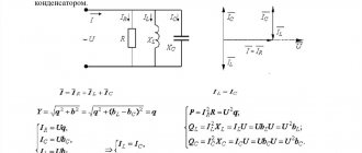
RLC circuit
As can already be seen from the diagram, for the description we need to write down the equation of the input impedance.
\Large Z_{in} = R + jwL — j\frac{1}{wC} (1)
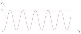
Further, to understand the processes taking place, it is convenient to work with capacities. Let's write the total power in the RLC circuit
\Large P = V_{rms} \cdot I_{rms} = \frac{V \cdot I}{ \sqrt{2}\cdot \sqrt{2}} = \frac{V \cdot I}{2} (2)
The equation involves the root of two, since the effective value of alternating current and voltage is used.
Now we write the power in complex form through the impedance from the equation (1).
\Large P=\frac{I^{2}Z_{in} }{2}= \frac{1}{2} I^{2} \cdot (R + jwL - j\frac{1}{wC} )
Let's open the brackets
\Large P=\frac{1}{2} I^{2}R + \frac{1}{2} I^{2}jwL — \frac{1}{2} I^{2}\frac{ j}{wC} (3)
Let's stop at this point and carefully look at what we got.
Parts of the equation
For greater clarity, we will describe each power and energy using the root mean square (also known as effective) value of current or voltage.
Recall that the effective value for a sinusoidal signal is found as:
\Large V_{rms} = \frac{V_{max}}{\sqrt{2}}
Then the power dissipated by the resistor is:
\Large P_{r} = \frac{I^{2}R}{2}
Energy accumulated in inductance:
\Large W_{L}= \frac{LI_{rms}^{2}}{4}
The energy accumulated in the capacitor, but expressed in terms of current:
\Large W_{C}= \frac{CU_{rms}^{2}}{2} = \frac{I_{rms}^{2}}{4\cdot Cw^{2} }
Let's return to expression (3) and write it using the powers and energies from the equations above.
\Large P = P_{r} + 2jw(P_{L}-P_{C}) (4)
This shows that resonance occurs when the accumulated energies in the capacitor and inductance become equal. Or, if we turn to equation (1) , the impedance of the inductor becomes equal to the impedance of the capacitor. The resonance point is characterized by the minimum input resistance (Z_in = R).
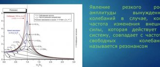
In an impedance plot, series resonance is shown in the figure below.
Impedance versus frequency.
As already mentioned, conditions for resonance arise when WL=WC. Let's equate the two energies.
\Large \frac{LI_{rms}^{2}}{4} = \frac{I_{rms}^{2}}{4\cdot Cw^{2} }
From here it is easy to find the resonant frequency.
\Large w_{0} = \frac{1}{\sqrt{LC}}
Next, we will find another important parameter characterizing the resonant circuit - this is the quality factor . Quality factor is often used to describe the amount of loss in a circuit. Also, using the quality factor, you can determine how susceptible the RLC circuit as a whole is to fluctuations.
In essence, the quality factor is the ratio of the accumulated (stored) energy in a cycle to the energy lost. Denoted as Q.
\Large Q_{0} =w_{0} \frac{W_{stor}}{W_{loss}} = w_{0} \frac{W_{L}+W_{C}}{W_{loss}} (5)
Let's next look at the formula for the quality factor for the resonant frequency w0. As already written above, at the resonance frequency the energy in the capacitor and in the inductance are equal. Let's take this into account in the formula (5).
\Large Q_{0} =w_{0} \frac{2W_{L}}{W_{R}} = w_{0} \frac{2\cdot \frac{I^{2}L}{4}} {\frac{I^{2}R}{2}} = w_{0} \frac{L}{R}
The same thing can be written through the energy of a capacitor.
\Large Q_{0} =\frac{1}{w_{0}RC}
The last thing to note about series resonance is the resonance bandwidth. What it is? In words, this can be described as follows: the passband for a resonant circuit is the frequency region that lies within the boundaries where the power dissipated by the resistor is less than half of the total power of the system. You can find the bandwidth like this:
\Large BW = w_{0} \frac{1}{Q_{0}}
The band boundaries can be found in a simple way, for example, from the frequency w0, step back in each direction by BW/2. This can also be done through the transfer function for the RLC circuit in relation to the resistor. Let's write the transfer function as the ratio Vr/Vin.
\Large \frac{V_{r}}{V_{in}} = \frac{IR}{I(R+jwL+\frac{1}{jwC})} = \frac{R}{R+\frac{( jw)^{2}LC+1}{jwC}}
Next, we multiply each term of the equation by jwC/jwC
\Large \frac{V_{r}}{V_{in}} = \frac{jwRC}{jwRC-w^{2}LC+1}
Now we find the module of the transfer function. Let me remind you that the module for complex numbers is found as:
\Large \sqrt{(RE)^{2}+(IM)^{2}}
Now let's write down the final version of the transfer function module.
\Large \left | \frac{V_{r}}{V_{in}} \right | = \frac{wRC}{\sqrt{(wRC)^{2}+(1- w^{2}LC)^{2}}} (6)
After we have written down the transfer function, let's return to determining the bandwidth. The passband for a resonant circuit is the frequency region that lies within the boundaries where the power dissipated by the resistor is less than half of the total power of the system.
In other words, to find the bandwidth, you need to set the conditions where half of the total power will be dissipated on the resistor. To do this, the amplitude across the resistor must be at least equal to:
\Large \frac{1}{\sqrt{2}}V_{max}
Knowing these conditions, let’s return to the equation taking into account the above (6).
\Large \frac{1}{\sqrt{2}} = \frac{wRC}{\sqrt{(wRC)^{2}+(1- w^{2}LC)^{2}}} (7)
Now we can solve equation (7) for w. After solving we get the following roots:
\Large w_{1,2} = (\sqrt{1+(\frac{R}{2\sqrt{\frac{L}{C}}})^{2}} \pm \frac{R}{ 2\sqrt{\frac{L}{C}}})_{w0}
Let's highlight the obtained frequencies on the impedance graph, which appeared above.
RLC Bandwidth
Parameters for construction.
Mathcad listing.
Connecting to the inductive coil circuit
Resonance in an electrical circuit
The inclusion of an inductor in a capacitive circuit immediately turns it into a CC. Depending on the connection diagram, there are two types of class 1 CCs: parallel and serial.
Parallel QC
In this circuit, capacitor C is connected to coil L in parallel. If a charged capacitor is connected to a coil, the energy stored in it will be transferred to it. A current will flow through the inductive coil L, causing an electromotive force (EMF).
The self-induction emf L will be aimed at reducing the current in the parallel circuit. The current created by this EMF and the discharge current of the capacitor are initially identical, and their total value is zero. The capacitor will transfer its energy Ec to the coil and will be completely discharged. The inductance, having received the maximum magnetic energy EL, will begin to charge the capacitor with a voltage of a different polarity. When all the energy from the inductance goes into the capacitor, the capacitor will be fully charged. Oscillations appear in the circuit; such a circuit is called an oscillatory circuit.
Parallel QC
For your information. If there were no losses in such a circuit, then such oscillations would never begin to fade. In practice, the duration of the process depends on the energy loss. The greater the losses, the shorter the duration of the oscillations.
Parallel connection of C and L causes current resonance. This means that the currents passing through C and L are higher in value than the current through the circuit itself by a specific number of times. This number is called the quality factor Q. Both currents (capacitive and inductive) remain inside the circuit because they are in antiphase, and their mutual compensation occurs.
It is worth noting! At fres, the value of R KK tends to infinity.
Sequential QC
In this circuit, a coil and a capacitor are connected in series with each other.
Sequential QC
In such a circuit, voltage resonance occurs, R of the circuit tends to zero in the event of the formation of a resonant frequency (fres). This allows a similar resonance system to be used as a filter.
Parallel Resonance RLC
Let us describe everything that was deduced for the sequential RLC resonance, but in a more condensed form.
Parallel RLC circuit
Expression for impedance Z_in :
\Large Z_{in} = (\frac{1}{R}+\frac{1}{jwL}+jwC)^{-1}
Graph of impedance versus frequency:
Z_in(w)
The resonant frequency is found in the same way as for series resonance and is equal to:
\Large w_{0} = \frac{1}{\sqrt{LC}}
Quality factor for parallel resonant circuit:
\Large Q_{0} = \frac{R}{w_{0}L} = w_{0}RC
The bandwidth is the same as in the serial RLC circuit, except that the quality factor must be for the parallel RLC circuit.
\Large BW = w_{0} \frac{1}{Q_{0}}
Definition of an Oscillatory Circuit
Rotation frequency: formula
Resonance phenomena noted in electrical engineering are clearly expressed in the circuits of oscillatory circuits (OC). Such designs are elementary systems capable of carrying out free oscillations of an electromagnetic nature. The CC itself in the circuit consists of the following elements:
- capacitor;
- inductors;
- current source.
Attention! The terminals of the circuit elements can be connected to each other in parallel or in series. It all depends on what result you want to achieve from resonance in the CC.
Application of oscillatory circuits
A detailed calculation of the oscillatory circuit allows you to accurately select the size of the required CC elements. This allows them to be used in electronic circuits in the form:
- frequency filters - in radio receivers, signal generators, converters and rectifiers;
- oscillatory circuits - for isolating and tuning a broadcast station to a specific frequency;
- power resonance filters – for generating a sinusoidal voltage.
On civil aviation aircraft, CC is used in generator frequency control units.
The benefits and harms of resonance
In order to draw some conclusion about the pros and cons of resonance, it is necessary to consider in which cases it can manifest itself most actively and noticeably for human activity.
Positive effect
The response phenomenon is widely used in science and technology. For example, the operation of many radio circuits and devices is based on this phenomenon.
- Two-stroke engine. The muffler of a two-stroke engine has a special shape designed to create a resonant phenomenon. It improves engine performance by reducing consumption and pollution. This resonance partially reduces the unburned gases and increases compression in the cylinder.
- Musical instruments. In the case of string and wind instruments, sound production occurs mainly when the oscillatory system (strings, columns of air) is excited until the phenomenon of resonance occurs.
- Radios. Each radio station emits an electromagnetic wave with a clearly defined frequency. To capture it, the RLC circuit is forcibly vibrated by an antenna, which captures all electromagnetic waves that reach it. To listen to one station, the natural frequency of the RLC circuit must be tuned to the frequency of the desired transmitter by changing the capacitance of the variable capacitor (the operation is performed by pressing the station search button). All radio communication systems, whether transmitters or receivers, use resonators to "filter" the frequencies of the signals they process.
- Magnetic resonance imaging (MRI). In 1946, two Americans, Felix Bloch and Edward Mills Purcell, independently discovered the phenomenon of nuclear magnetic resonance, also called NMR, which earned them the Nobel Prize in Physics.
Negative impact
However, the phenomenon is not always useful. You can often find references to cases where suspension bridges broke when soldiers walked across them “in step.” At the same time, they refer to the manifestation of the resonant effect of resonance, and the fight against it becomes large-scale.
- Motor transport. Motorists are often annoyed by noise that occurs at certain vehicle speeds or as a result of engine operation. Some slightly rounded parts of the body resonate and emit sound vibrations. The car itself, with its suspension system, is an oscillator, equipped with effective shock absorbers that prevent sharp resonance from occurring.
- Bridges. The bridge can perform vertical and transverse vibrations. Each of these types of oscillations has its own period. If the lines are suspended, the system has a very different resonant frequency.
- Building. Tall buildings are susceptible to earthquakes. Some passive devices help protect them: they are oscillators whose natural frequency is close to the frequency of the building itself. Thus, the energy is completely absorbed by the pendulum, preventing the destruction of the building.
Next
MiscellaneousWhat is active power?