Operating principle
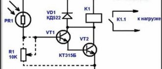
The diagram shows the principle of operation of the device.
Photoresistor PR1 reduces its resistance to several Kohms as the illumination increases, due to which phototransistor VT2 opens, which turns on photorelay K1, and this device, in turn, will begin to transmit signals. Diode VD1 protects the circuit from self-induction. Thanks to this principle, even very weak signals can turn the light on or off. Photo - Photo relay circuit
The main working part is a photocell, which is a gas tube in which gas ionization occurs. It has a cathode that is capable of producing electrons in proportion to the intensity of light directed towards it, and the tube is also equipped with an anode to collect electrons.
Photo – Photo relay
Whenever a negatively charged surface is placed in an atmosphere of an ionizable gas, such as mercury vapor or any inert gas, electrons are transferred to it. There, by using the Fermi-Dirac velocity theory, electrons are accelerated depending on the strength of the applied electric field.
Photo – Photo relay TDM
These electrons travel a relatively short distance before colliding with an ionizing gas atom. When an electron, which has constant kinetic energy, passes through an ionizing substance, it disturbs the atoms it encounters. Also, its trajectory of action may change periodically. If the material is gaseous, the resulting fragments or ions may move away from each other. But if electrons are knocked out of atoms, then they move in one direction, and the residual positive ions move in the opposite direction. The output of the ionization type or photocell depends on the number of electrons at the anode.
It is the movement of electrical particles in a certain sequence that causes the device to switch. It must be said that this is especially convenient for devices with a motion sensor Finder, Legrand.
Operating principles and basic components of photo relays
What is a photo relay? The executive circuit of the device consists of the following components:
- A sensor, which is an electronic component that detects the presence of visible light, infrared radiation, and/or a source of ultraviolet radiation.
- Signal amplifier (sometimes complete with a converter of one type of emitted energy to another).
- The executive element is a microcontroller that contains a bipolar field-effect phototransistor.
- Control unit.
- Power supply.
Photosensors
Most photo sensors are semiconductors that have a property called photoconductivity. It consists in changing the parameters of electrical conductivity depending on the intensity of light radiation falling on the material.
How the photo relay works is clear from the figure. Photovoltaic devices can be divided into two main categories: those that generate electricity when illuminated - photovoltaic or photoemissive emitters - and those that change their electrical characteristics in some way (photoresistors or photoconductors).
Types of photovoltaic devices (left - semiconductor, right - photoemissive)
Thus, a typical photo relay design may include the following versions of photo sensors:
- Photoemissive cells are devices that release free electrons from a photosensitive material, for which a photon with sufficient energy must hit the light-receiving surface. The amount of energy that photons have depends on the frequency of the light: the higher the frequency, the more energy the photons have, converting light energy into electrical energy;
- Photoconductive elements that change their electrical resistance when exposed to light. Photoconductivity occurs when light strikes a semiconductor material, which controls the current flowing through it. The most common photoconductive material is cadmium sulfide, used in LDR solar cells;
- Photovoltaic cells. The principle of operation is based on the generation of emf in proportion to the received energy of radiant light, which is similar in its effect to photoconductive components. Light energy hits two semiconductor materials placed together. This produces a voltage of at least 0.5 V. The most common photovoltaic material is selenium, used in solar cells;
- Photoreceiving devices. These are semiconductors (photodiodes or phototransistors) onto which light must be directed to control the flow of electrons and holes through the PN junction. Photo relays use electronic components specifically designed for detector application and light penetration, with their spectral response tuned to the wavelength of the incident light.
Photo relay based on LDR elements with power supply
Photoresistor
A photoconductive sensor does not produce electricity, but simply changes its physical properties when exposed to light energy. The most common type of photoconductive device is the photoresistor, which changes its electrical resistance in response to changes in light intensity.
Photoresistors are semiconductor devices that use light energy to control the flow of electrons and therefore the current flowing through them. This element is usually called a light dependent resistor or LDR.
The operating principle of a photo relay on the corresponding photosensor is shown in the figure:
Design and principle of operation of a photoresistor
As its name suggests, a light dependent resistor (LDR) must be made from an exposed semiconductor material, such as cadmium sulfide, which changes its electrical resistance from a few thousand ohms in the dark to several hundred ohms when light shines on it, creating hole-electron pairs in the material.
The effect is to improve the conductivity of the photosensor with reduced resistance to increase illumination. Photoresist cells have a long response time, which is needed to respond to changes in light intensity.
Photosensitive materials
The materials used as semiconductor substrates are lead sulfide (PbS), lead selenide (PbSe), indium antimonide (InSb), which detect light in a wide range of wavelengths. The most commonly used of all photoresistive light sensors is cadmium sulfide (Cds) because its spectral response curve most closely matches that of the human eye, requiring the presence of any light source. The peak sensitivity wavelength for a cadmium sulfide solar cell is 560 to 600 nm in the visible spectral range.
The ORP12 conductive element is often used as a photosensor. This light-dependent resistor has a spectral response of about 610 nm in the yellow to orange light region. The resistance of the element when not illuminated (dark resistance) is very high, around 10 megohms, which drops to 100 ohms when fully illuminated (nominal resistance).
To increase dark resistance and therefore reduce dark current, the resistive path forms a zigzag pattern on the ceramic substrate. The CdS photocell is a very inexpensive device and is often used for automatic dimming, as well as for determining the time of darkness or twilight, in photo relays for street lighting.
A typical diagram of an electronic control unit, which uses light-conducting elements made of cadmium sulfide, is shown in the figure:
Motion sensor and light sensor
Having finished disassembling the connection and connection of the photo relay for street lighting, we will move to the premises under the roof. A similar system can also be found here. In essence, other than the vastness of the space compared to the outer limits, there are no differences. At night, as on the street, nothing is visible indoors. And here we also need an illumination system to disperse the darkness during periods of darkness. But not every prudent owner is willing to pay extra money for electricity that is wasted senselessly most of the time. After all, the need for light, although it arises occasionally at night, does not last throughout its entire period. This is where the connection of several components will come to the rescue: a light and motion sensor. That is, the system itself will only work at night and precisely at the time when someone moves within the range of the sensors. At the moment both factors are determined, a command will be given to the lamp to turn on. The main thing is not to forget to set the photo relay to the current level of illumination of the space and the motion detector to the desired sensitivity.
Connection diagram of the motion detector and light sensor to the lamps:
A quick note regarding the motion detector. It must be either infrared or ultrasonic. The reason is simple - the optical one, while the light is off, will not “see” the movement of the object in the touch field, and therefore will not give a command to activate the lamps.
Description of photo relay
Sensitive photo relay based on a triac GOST 51324.2.1-99. is an optocoupler device consisting of LEDs optically connected to the contacts of electrical appliances. It is also often called a twilight LED sensor, a day-night device, etc.
Photo – Photo relay photo
Photo relays offer various advantages over mechanical time relays:
- Small size. Housed in small units such as USOP, the fixture is designed with a reduced board;
- Long service life. In the absence of mechanical contact, the shelf life is significantly extended due to the fact that wear is completely absent;
- Low current drive. This device can operate with an incoming current of even a few milliamps without an amplifier. Thus, neighboring devices can do without drivers;
- Quiet operation. In the absence of mechanical contact, the contactless relay does not make any sounds during operation;
- High speed. Photo relays are about 10 times faster than their mechanical counterparts (which take a few milliseconds to switch).
- Excellent performance, many appliances come with a timer.
The components of the device are: three contact wires for connecting to a common network, a magnetic starter, and an armature.
Photo - Photo relay disassembled
Video: simple photo relay
Connecting a photo relay
The connection diagram for photo relays for street lighting comes in two types: with two wires or a number of wires that is a multiple of two when connecting a number of lamps or lanterns directly to the relay, or with three terminals.
All modifications of relays with three terminals according to the international standard have three multi-colored wires. To connect the photo relay to the lighting, it is necessary to make wire connections according to the drawing. This usually happens as follows when the relay has 3 wires of different colors:
- Brown. Connects to one of the AC wires directly in the relay wiring box;
- Blue. It is a “zero” wire, connected to the neutral terminal in the wiring box, from which a wire goes to the lighting fixture;
- Red. The wire from the light relay is connected to the connector in the installation box, from which the phase is supplied to the light device.
With a two-wire circuit, the phase with the neutral wire is connected to the two corresponding contacts of the relay box, and the lighting devices to the other two; more of them can be connected in parallel.
There are modifications of photo relays used for operation in electrical networks with a grounding bus; for this purpose, the mounting box is equipped with an additional terminal for connecting the grounding wire (green).
A diagram of how to connect a photo relay is always drawn on the device body itself and is indicated in the technical data sheet, so it is almost impossible to make a mistake when connecting.
How to connect a device to a street lamp: diagrams and principles
When connecting a simple device, you need to familiarize yourself with its design. The main element is a photodiode, which can be located outside or inside the housing. In the first case, the sensor is mounted outdoors, and the electronic unit is connected to an electrical panel indoors. If the sensitive part is located internally, the device is mounted outdoors.
The device is small in size and easy to mount
Knowledge of the design features of the device allows you to connect it to the flashlight as efficiently as possible
Therefore, it is important to determine the type of photo relay, purchase a high-quality device, select a circuit, and then begin connecting the sensor
Photo relay on the diagram
The correct connection diagram greatly facilitates self-installation of the device. In the electrical diagram, the photodiode is presented in the form of a conventional graphic symbol, which is a triangle on the axis of symmetry with arrows directed from top to bottom. On simple diagrams, the device can be designated as a circle or rectangle with the inscription “FR”.
The arrows in the diagram symbolize the reflection of light
Connection
The bracket with the device is mounted in a shaded place. Tree foliage, canopies, and precipitation should not affect the operation of the device. After determining the location, you need to find out the number of lamps for which control is required. One photo relay is mounted per light source. If you use a large number of flashlights, then it is best to use a controller. It receives a signal from a photosensor and allows you to control several lamps simultaneously.
The connection diagram for one lamp is very simple
The design of the device may include terminals, which simplifies connection. They are necessary for clamping wires. The cable of each color is connected to the corresponding wire of the lamp and power circuit. If there are no terminals, then a junction box should be installed. The device body must be protected from moisture and precipitation. Well-known manufacturers indicate on the packaging or in the instructions the connection diagram of the element.
Relay installation and grounding
If a TN-S or TN-CS type grounding system is used in an apartment, house or street, the electrical circuit is powered from the network by a three-wire cable (phase wire, neutral, ground). But for connecting lamps with TN-C type wiring, the connection will differ only in that there is no PE conductor.
The adjustment is made according to the manufacturer's settings. Before connecting the lamp, be sure to check the passport, certificate and patent of the seller, so that later you do not have to make major repairs to the wiring in the apartment. It is advisable to install a separate machine for this controller in the distribution board (cabinet).
You can buy a photo relay at any electrical store; the price directly depends on the brand and area of operation (street - FR-601 IEK, FR-602, facades - FRSU-1-0 uhl 4.2, FRSU-2-0 and other types). The most popular models are FR-1 12 volt, UTFR-1M, CSM, LUNA 110 AL, TWS-1, TWS-1M, AWZ-30, ABB (ABB), LXP-01, DLS-1/50, AZH-S , AS-7, RFS-11, FB-2-16A (range 2-4 kW), LUX 2.
Photo - Connecting photo relay FR-601
Where to put
The installation location is selected so that the photocell is not exposed to light from a lamp, window, or advertising board. When the house is located near the roadway, the light from the lights of passing cars should not be directed at the device. The choice of location is limited by height requirements - 1.8-2 meters from the ground (if installed higher, a stool/chair or ladder/step-ladder will be required for adjustment).
Solving this problem is made easier by using some tricks. The photo sensor can be protected with a piece of black plastic pipe of the appropriate diameter, 15-20 cm long. The cutting angle is 30-45° from the pillar or wall. If there is only one spotlight, the photo relay is placed on the other side of the pole. The parameters are adjusted more accurately if the sensor is placed on the west or east side.
Microprocessor photo relay
Modern technologies have also affected photo relays. Devices based on microcontrollers are increasingly being used, which allow not only determining the presence of light flux, but also combining many other functions. Moreover, the expansion does not require significant changes in the hardware component; it is enough to modify the internal program.
A microcontroller is a small computer, initially focused on controlling devices depending on external factors and an algorithm. In addition, its capabilities are quite sufficient for joining a common digital network that unites groups of equipment of various types.
It is also worth mentioning industrial samples of photo relays equipped with a “smart” part. But their functionality is usually limited by the manufacturer. Therefore, it is better to consider another system. For example, Arduino. Its capabilities are quite sufficient to control the light, turn off the line day and night, send messages about the current mode in use or signal problems in the performance of the lamp.
On the hardware side, everything that does not directly relate to the control functions is assigned to additionally connected “shields” to the Arduino. In the above diagram, the latter will refer to the clock, the light sensor and the relay itself. The issue of sending the status to the final owner is resolved using the GSM communication module, which will send SMS about the current operating mode of the system.
The design concept is quite simple:
There is a note regarding the above assembly
Please note that the relay module has external power supply. This is done in order to avoid current surges, since the shield takes a lot of electricity from the common line and can cause a voltage “dip” when switching
Separate power supply is also recommended for SIM800L (in the diagram above it is connected directly to the Arduino itself). Also, the GSM communication module is quite a consuming element - it needs to generate a certain power to connect to a cell tower, and it can only take energy for this purpose from the supply line.
As for the software part, anyone familiar with programming Arduino microcontrollers can write the appropriate algorithm. Moreover, there are many codes on the Internet.
Despite the functional simplicity of the photo relay, it has enough niches for application. Moreover, small capabilities are expanded by adding new ones due to slight complication of the circuit and the use of microcontrollers.
Lighting control using a time relay
Time relays are widely used in automation circuits, including lighting control.
Time relays can be divided into two large groups:
- Programmable time relays - the relay closes and opens its contacts in accordance with a given program;
- Timers - a time relay closes and opens its contacts for a specified time after applying a control signal.
Programmable time relays and timers can be electronic or electromechanical.
Programmable time relays can be with daily (the same program is repeated every day), weekly (the same program is repeated every week) and annual cycle (the program is set for a year).
Basic circuit and operating principle
Let's consider the operation of a lighting control circuit based on a programmable time relay operating according to one daily program.
Lighting control using a time relay. Basic scheme
Let's say the lighting should be turned on every day from 9:00 to 18:00. We set the current time in the time relay and set a program according to which at 9:00 the relay should close its contacts for a period of 9 hours. Every day, when 9:00 comes, the KT1 time relay closes its contacts, the power circuit is closed and the lighting is turned on. After 9 hours, the program ends and the relay opens its contacts - the lighting turns off.
Schemes for controlling lighting of several lines using a time relay
To control several lines according to one program, time relays are used in combination with contactors. Contactors turn the power on and off, and a time relay controls their operation.
Lighting control using time relays and contactors
Power is supplied to the coils of contactors 1KM1, 2KM1, 3KM1 through a three-position switch SA1 with a neutral position:
- In the “Manual” position, power is directly supplied to the coils of the KM contactors and they close their pairs of contacts, the lighting is turned on in accordance with the specified program;
- In position “0” the power supply circuit of the contactor coils is broken and the lighting is turned off;
- In the “Automatic” position, power is supplied to the contactor coils through the contacts of the KT1 time relay. Turning the lighting on and off is controlled by a time relay, closing and opening its contacts in accordance with a given program.
If necessary, you can supplement the circuit with an HL signal lamp connected parallel to the contactor coils, which will inform you that the lighting is turned on.
Lighting control using time relays for staircases
To save energy and control lighting from several places, use a time relay from a group of timers. This type of relay closes or opens its contacts after a control signal is applied to their coil; the closing or opening of the contacts occurs with a specified time delay.
This type of time relay is mainly used in motor control circuits and ATS (automatic transfer switch) circuits, but is also used to control lighting. For example, to control the lighting of staircases.
Let's consider the use and operation of a time relay to solve this problem:
- At the initial moment of time, the KT1 relay contacts are open, the lighting is turned off. Buttons SB1, SB2... are installed on each floor of the staircase and connected in parallel to the control contacts of the KT1 time relay.
- When you press any of the SB buttons, a control signal is sent to the coil of the time relay KT1, it closes its contacts, the lighting turns on, and the time relay begins counting.
- After a specified time, relay KT1 opens its contacts and the lighting turns off.
- If, when the relay contacts are closed (i.e. before the set time has expired), a new control signal is received, then the time countdown begins anew.
Staircase lighting control using a time relay
Thus, a person entering the staircase presses the push-button switch SB and turns on the lighting. On the next floor he presses the button again, etc. After a specified time, the lighting in the staircase turns off. The shutdown delay setting is selected so that a person has enough time to walk from one pushbutton switch to another.
This circuit can also be used to control lighting in corridors. It allows you to organize the switching on of lighting from several places (as when using a pulse relay) and at the same time save energy.
payaem.ru
The task of a photo relay is to control lighting; often, it is a circuit with a photosensitive element that controls the switching on of lighting at night. Radio amateurs have developed many different photo relay circuits; we present to your attention simple and reliable circuits based on various photosensitive elements: photoresistors, photodiodes, phototransistors.
The first photo relay circuit is based on a photodiode and is quite suitable for beginners, as it is easy to manufacture and does not contain rare elements. An LED is used as a load after the switch; of course, another logical circuit or relay can be used instead. In this circuit, the photodiode is connected through a current stabilizer; the circuit in this connection makes a significant difference in lighting and darkening the photosensitive element and therefore does not require an additional amplifier. With a sudden change in illumination, the voltage on the photodiode changes from 0 to the circuit supply voltage level. You can easily assemble and adjust this circuit in a couple of hours on a breadboard. Almost any brand of photodiode can be used.
Details:
In this circuit, FD 256 was used, but the circuit also works with phototransistors. VD1 and VD2 can be installed with any silicon diodes. Transistors can also be any low-power ones. As I already said, the first transistor works as a current stabilizer and the larger R2 is, the greater the sensitivity of the circuit, but do not overdo it with the settings. The cascade on the second transistor is an emitter follower, the third transistor is a regular switch.
We offer another simple circuit with a minimum number of parts and high sensitivity. This sensitivity is achieved by including transistors VT1 and VT2 as a composite. In such a connection, the total gain will be equal to the product of the coefficients of the component transistors. Also, due to this inclusion, a high input impedance is achieved, which allows the use of a photoresistor and other high-resistance signal sources.
Principle of operation:
The circuit works very simply - with increasing illumination, the resistance of the photoresistor decreases to several kiloohms (in the dark - several megaohms), this leads to the opening of transistor VT1. The collector current VT1 will open the transistor VT2, which in turn will turn on the relay and it will turn on the load with its contacts. So that at the moment the relay is turned on, self-induction does not occur and the low-power signal of the photoresistor is converted into a signal sufficient to turn on the winding, VD1 is turned on.
Details:
To adjust the sensitivity of this circuit, which can sometimes be excessive, you can put a variable resistor in the circuit, which is shown in the dotted line in the diagram. The power supply of the circuit depends on the operating voltage of the relay and can be in the range of 5-15 V. With a power supply of 6 volts, you can use RES 9, with 12 volts RES 15, RES 49. The winding current when using the specified transistors should not exceed 50 mA. if you replace VT2 with a more powerful type KT 815, the output can be larger and it is possible to use more powerful relays. It should be taken into account that as the power increases, the sensitivity of the photo relay increases.
Another circuit is assembled on an operational amplifier and also does not contain a large number of parts. The op-amp in this circuit is included as a comparator (comparing device), and the photodiode is turned on in photodiode mode, power is supplied to it so that it is biased in the opposite direction.
Due to this inclusion, when the illumination decreases, the resistance of the LED increases, and this leads to the fact that the voltage drop across resistor R1 decreases, and accordingly drops at the inverting input of the comparator. At the non-inverting input, the voltage is set using R2, and is threshold, that is, it sets the response threshold. When the voltage at the inverting input decreases below the threshold, a voltage level will appear at the comparator output that will open T1 and turn on the relay.
Details:
The transistor can be used with any low-power NPN type KT 315, 3102. Op-amp as a comparator type K140UD6 - UD7, or similar. To power the circuit, use a rectifier with a voltage of 9-12 volts; select a relay with the appropriate winding response voltage.
Setting:
Setting up the device consists of setting the threshold voltage; it should be configured in such a way that it turns on already at dusk. To adjust the response threshold, you can use an adjustable incandescent lamp in a darkened room. To get rid of possible relay bounce when triggered, you need to connect a capacitor of several hundred microfarads in parallel to the coil.
How to install a photo relay
You need to use special holes to complete the installation. You just need to follow a few important rules.
- It is imperative to check what voltage the supply network operates with before installing the magnetic starter and other elements. It is necessary to have an indicator of approximately 220 V. The minimum deviation is 10 percent up or down. We also need to make sure that the protection complies with all the rules. This applies to the fuse, circuit breaker.
- Installation is prohibited if there are chemically active substances nearby. Do not place with flammable or flammable materials.
- The connection diagram suggests that the base of the device should only be at the bottom, not at the top.
- The light from the lamp being switched on should never fall on the photosensor.
Installation of photo relay
It is not difficult to install a photo relay with your own hands; it is only important to exclude the direct influence of the adjustable light source and protect the device from adverse external influences: moisture, direct sunlight, temperature changes
For industrial devices, there are a number of standards that such solutions must comply with: GOST (domestic) and IP (international). It is more difficult to ensure that a homemade photo relay is protected from environmental factors, although it is theoretically possible. But for those who want to install such a device in their yard, near their entrance or garage, it is better to first consider the solutions offered on the market - without having the necessary knowledge and experience, it will be extremely difficult to bring the photo sensor to working condition with your own hands.
Selecting a photo relay
There are devices on sale, both domestic and foreign, with a similar set of functions. When choosing a device, you should be guided by the following rules:
- The total power of the connected luminaires must correspond to the rated current load specified in the relay passport and not exceed it.
- The supply voltage and type of current (DC or AC) must correspond to the selected model.
- For outdoor installation, it is necessary to use a device with a degree of protection not lower than IP. In the case of a remote sensor, the IP for the electronic unit may be reduced if it is installed in a protected place.
- If you need flexible settings, you should choose a relay with additional functions or a professional model.
Photo relay operation
At high illumination, the photocell resistance (LDR) is low, hence the voltage across it is almost equal to the supply voltage. For this reason, the BC558 pnp type transistor is closed, so the second BC548 npn type transistor is also closed. The relay will not be active.
At night, the resistance of the photocell (LDR) increases significantly, as a result, the voltage across it will drop, and this will lead to the opening of BC558 (pnp transistors open at a negative voltage at the base in the region of 0.6 volts relative to their emitter). Following this, transistor BC548 opens, and this leads to activation of the relay.
Step-by-step installation instructions
Right away I would like to move a little away from the topic and advise you to simultaneously connect a photo relay and a motion sensor for lighting. When paired, these two devices will allow you to turn on the lamp when darkness falls, only if a person appears in the detection zone. If there is no one on the site, the lights will not light up, which will significantly save energy.
The installation method depends on what protection class and type of mounting of the twilight light switch you purchased.
Today there are various manufacturing options, namely:
- with mounting on a DIN rail, on a wall or on a horizontal surface;
- outdoor or indoor use (depending on IP protection class);
- photocell built-in or external.
In the instructions, we will provide an example of installing a photo relay for street lighting with wall mounting. The connection is made at the stand for convenience, especially since this is just an example.
So, in order to connect the photo relay to the lamp yourself, you must complete the following steps:
- We turn off the power at the input panel and check the presence of current in the distribution box from which we will run the wire.
- We stretch the power wire to the installation site of the photo relay (next to the lighting fixture). We recommend that you use a three-core PVS wire to connect the twilight switch, which has proven itself to be a reliable and not too expensive conductor option.
- We strip the conductors of insulation by 10-12 mm in order to connect them to the terminals.
- We create holes in the housing for inserting the cores in order to connect the photo relay to the network and the lamp.
- To increase the tightness of the case, we attach special rubber seals in the cut holes to protect against dust and moisture getting inside. By the way, the twilight switch must be placed in such a way that the inlet holes are at the bottom, which will prevent moisture from penetrating under the cover.
- We connect the photo relay for street lighting according to the electrical diagram that we provided above. As can be seen in the photo, the input phase is connected to connector L, and the input neutral to N. A separate screw terminal with the appropriate designation is provided for grounding.
- We cut off the required length of wire to connect the photo relay to the light bulb (in reality, it could even be an LED spotlight). We also strip the insulation by 10-12 mm and connect it to terminals N' and L', respectively. The second end of the conductor is brought to the light source and connected to the terminals of the socket. If the lamp body does not conduct current, grounding does not need to be connected.
- Installation and connection are completed, let's move on to setting up the photo relay with our own hands. There is nothing complicated here; the kit includes a special black bag, which is necessary to simulate night. On the body of the light sensor you can see a regulator (signed with the abbreviation LUX), which is used to select the light intensity at which the relay will operate. If you want to save energy, set the rotary control to minimum (o). In this case, the signal to turn on will be given when it is completely dark outside. Usually the regulator is located next to the screw terminals, a little to the left and above (as shown in the photo).
- The last step of connecting the photo relay is to attach the protective cover and turn on the power on the panel. Once you do this, you can proceed to testing the device.
That's all I wanted to tell you about how to install and connect a photo relay with your own hands. We also recommend that you watch a visual video lesson, which shows in detail the entire essence of electrical installation.
Instructions for connecting a Feron photo relay
Finally, it should be said about which manufacturers of twilight switches are of the highest quality. Today it is recommended to give preference to products from companies such as Legrand, ABB, Schneider electric and IEK. By the way, the latter company has a fairly reliable model - FR-601, which has many positive reviews on the forums.
Application and connection
Electronic devices with a built-in photosensor of light are used to organize and control automatic street lighting, external façade, driveway or household lighting. Often combined with it, console lamps of the housing and communal services type are used, which are equipped with protective glass and a special grille.
The device operates on a very small microcircuit and transistors, and instructions are often given on the case on how to properly connect the device. We use a light control switch to demonstrate step by step how to install the fixture. Despite its externally small size, this device does an excellent job of lighting courtyards, parks and gardens.
Photo - photo relay FR-3
In general, photo relays for street lighting are recommended to be installed in the middle position. To install the switch yourself, you need to use a special bracket that is attached to the wall. The canopy is installed directly into the photo relay using a screw. The installation location depends on the lighting; try to choose an area where nothing prevents the sun's rays from hitting the working surface of the device, otherwise interference will begin on the photodiode and the device will not work correctly. Depending on the characteristics of the device, the presence of trees, furniture, curtains, etc. in front of the photo relay is not allowed.
The diagram of the photo relay and its principle of connection to the network is most often depicted on the box of the device, it is very convenient, you do not need to look for one that is suitable specifically for your device. Detailed instructions on how to connect a photo relay with your own hands:
- There are three wires coming out of the relay: brown, blue and red. Based on standard parameters and indicators, brown is a phase cable, red is an extension wire, goes like switching to a lamp, blue is zero (if you are developing a homemade relay, then you need to take these branches into account);
- In order for everything to be connected correctly, it is necessary to connect the wires to the console lamp as a load, this is demonstrated by the circuit designation.
To check that the connection is correct, you need to plug in the starter and see if the spotlight or flashlight works.
Photo - Connecting a photo relay
Selecting device parameters
Before you buy a photo relay, you need to determine the technical characteristics of the device:
What voltage is it designed for? In most cases, this is 220 volts; imported models may have a requirement for 110 or 127 V. There are 12 and 24 V devices (to connect these to a regular network, you will need a power supply). Look at the panel to find out your network voltage. Maximum load current value. Most often, this parameter has a range from 5 to 16 A. It is selected based on the number and power of light sources connected through a photo relay. Sensor response range. In the standard version, the devices have limits from 5 to 50 Lux (lux is a unit of illumination measurement). More expensive models have more precise adjustment. Device power consumption at rest (from 0.1 to 1 W) and when triggered (from 2 to 10 W). Time interval (from 15 to 30 sec.) in case of accidental darkening of the photocell. Keeping the sensor briefly exposed to strong shadows or headlights will prevent false alarms. The degree of protection of the device body from external factors. For street lighting, they usually choose the index IP 65 or IP 44; the IP 40 marking indicates that the photo relay can be used outdoors only with a protective casing. The maximum permissible outside air temperature for normal operation of the photo relay, this range is from -20 to +50 ⁰С. The dimensions of the device are selected depending on the location of the device, the dimensions of the shield
Whether a compact external part is needed or this is not so important, everything is selected individually.
Selection of photo relays for outdoor lighting
Before you go to the store to purchase a photo sensor to adjust the street lighting system, you should decide on the number and type of lamps to be connected. For one or two flashlights, a relay is enough, the lighting electrical appliances will be connected directly to it.
If there are a lot of light bulbs, then the photo relay will not be able to withstand the current passing through it. In this case, equipment with a magnetic starter is required.
Here, a photosensitive switch triggers a special device, through which the lighting equipment is already powered. Those. a lot in choosing a photosensor model depends on the power of the luminaire circuit connected to it.
A special approach and mandatory preliminary calculations require the selection of photo relays for a solar-powered street lighting system. Its power and the number of connected devices directly depends on the average annual number of sunny days in the region, as well as on the number of solar panels in the circuit.
The more light bulbs you plan to connect to the photo relay, the higher its switched current parameters must be - there are now devices on the market with a current rating in the range of 6–63 Amperes, there is plenty to choose from
Based on the type of connection to the electrical network, light control relays for street lighting are divided into:
- single-phase (household, for 220 V network);
- three-phase (for 380 V networks).
However, the switching relay itself and the entire circuit with the photosensor are powered by 12 V, which comes from the step-down transformer. The choice in favor of a single-phase or three-phase device depends solely on the network of light bulbs connected to it and the power it consumes.
To install control photo relays for street lighting in private homes, it is best to choose ordinary household models for 220 V. They will be more than enough, especially if economical LED lamps are connected to them.
Technical parameters - what to look for
Some imported electrical appliances are designed for 110 or 127 V networks. Rarely, you can stumble upon them in lighting stores. They simply cannot work in Russian 220 V networks. They will require the installation of an additional transformer. It is better to immediately take the equipment whose connection will have fewer problems.
The first and main indicator is the degree of protection . For outdoor installation, you should choose models with a sealed housing IP65 or higher. And for installation under a roof or in a protected shield, a device with IP44 is quite suitable.
The second parameter is the response threshold , which is expressed in Lux. Typically this range is from 2 to 50 Lux. The photo relay has an adjustment for this indicator so that the user can adjust it to his personal preferences. It is worth purchasing a device with an unregulated response threshold only as a last resort.
The third indicator is the type of lamps connected . Often, a photo relay is designed exclusively to work with incandescent light bulbs that create an active load.
To connect fluorescent devices with an already reactive load, you need to take a different type of twilight switches. And to connect mercury or sodium lamps, you need equipment with an additional protective circuit designed for inrush currents.
When choosing a relay with an external photocell, it is necessary to take into account the length of the cable between them - it has certain limitations, you cannot change it to a larger one
And the last parameters are dimensions and weight . The largest part of the photo relay is the power supply with a step-down transformer inside. The photosensor itself (LED) has very small dimensions.
Much more space is occupied by a contactor or magnetic starter, through which lighting devices are connected. All this should fit in the electrical panel or near the lamp.
Are additional features important?
Many models of light-control relays are complemented by a motion sensor and a timer. The first guarantees that the lighting is turned on only when a person moves through the controlled area, and the second allows you to completely turn off the device during the day, regardless of the level of natural light.
In fact, all photo sensors are configured at the factory so that when briefly illuminated by the headlights of a passing car, they simply do not operate
The most expensive models are photo relays with an electronic display and a programmable controller. These devices allow you to set your own work program for each season and occasion.
For example, in winter the lighting will turn on earlier, and in summer later. You can also provide for turning off the relay itself, along with street lamps, after one in the morning, so that they do not burn energy in vain.
DIY outdoor LED floodlight installation
LED floodlights for illuminating suburban areas have become very popular today. They are economical, provide a powerful, bright beam of light, and perfectly illuminate a certain area. For more efficient use, motion or light level sensors are additionally installed, which automatically turn on the lamps when moving or when it gets dark. You can choose and purchase high-quality and inexpensive LED spotlights here.
One of the advantages of LED street lights is the simplest installation, which you can do yourself
Site selection When planning installation, careful attention should be paid to site selection. According to accepted safety standards, street floodlights can be mounted at some distance from flammable materials and surfaces
High-power lamps must be installed so that there is an air gap between the housing and the wall. Additionally, you can protect the surface (especially wood) with a sheet of tin. When using light and motion sensors, care should be taken that they are not obscured, otherwise they simply will not work. The position of the future spotlight depends on the requirements for illumination and the direction of the light beam: • car parks and areas in front of the house are illuminated by lamps, the light from which is directed vertically downwards; • gates near the garage or fence are illuminated by spotlights, the beam of light of which is directed horizontally; • for paths, lawns, and facade walls, you can use lamps whose luminous flux is directed strictly upward.
The procedure for installing an LED spotlight The procedure for installing an LED spotlight on the street with your own hands includes the following steps: • a cable is pulled to the installation site, observing all safety standards and regulations (it is best to use a multi-core copper cable); • the lamp is applied to the selected place, with a simple pencil you should carefully mark the fastening points on the surface, check their horizontalness with a building level; • the spotlight is screwed on with self-tapping screws, the type of which depends on the surface material (wood or metal); • when fastening to a concrete wall, you must first drill holes for dowels or metal anchors with a hammer drill; • the spotlight is firmly mounted on the wall; it should not move or wobble easily.
The next step is to connect the lamp to the electrical network: • the line is de-energized; using an indicator screwdriver, you should additionally check that there is no phase on the cable (all measures should be taken to ensure that it does not appear accidentally); • the lamp contact box opens (it is located outside or inside the spotlight body, which depends on its model); • the power cable is inserted through a small hole (it has a special seal that protects the box from moisture); • power wires are connected to the terminal block (black or blue wire goes to zero, yellow or green goes to ground, brown or red goes to phase); • the box cover is put in place, all screws are tightened, after which it is necessary to check the installation of all seals; • the lamp is put in place, electricity is connected; • The spotlight can be turned on to check that the work has been done correctly.
Attention: When checking the performance of the spotlight, you should remember that it does not cool down immediately after turning off, remaining very hot for some time! If you purchased a 12 V spotlight, a mandatory connection element is a separate power supply or transformer, which is not required if you use conventional energy-saving lamps. A large selection of which is here https://salonlustr.com.ua/c9_14-Lampi_energosberegayushchie
Outdoor LED floodlights can be mounted in any convenient place. To save energy, it is best to immediately provide a special motion sensor that turns on the lamp if any moving person or object enters its field of view. Such sensors can be equipped with light indicators that turn off lamps during daylight hours.
WE RECOMMEND READING
- 08/04/2016Which lighting to choose for a nursery
- 09.29.2014Installation of electrical wiring in a wooden house
- 11/24/2014 Faceted metal support for lighting
- 11/24/2014 We understand electric household boilers
Specifications
Supply voltage. Almost all light relays are designed for a supply voltage of 220 V. Sometimes models are sold with power from 12 or 24 V DC or 110 V AC, in which case they must be connected through a step-down transformer.
Load level. This parameter is given for active loads in the form of conventional incandescent lamps; when using fluorescent lighting devices, this parameter is lower. Less commonly, in imported models, instead of load power, the maximum current is indicated.
Operation threshold. It is usually adjustable in a wide range of 2-300 Lux. To save energy, the lowest response threshold is set - 2 Lux, corresponding to the illumination of deep twilight. Cheap photo relays (usually from a Chinese manufacturer) do not have an adjustment of the response threshold; their preset response value is 5-15 Lux.
Delay time. There are situations when a short-term light flux hits the photocell (headlights, lighter, flashlight). To avoid turning on the lights on the entire street, there is a delay in the response time when turning on and off. This value varies between 15-60 seconds; some imported models have a response threshold of 100 seconds.
Power consumption at rest. For standby mode, this value is small and ranges from 0.1-0.5 W.
Degree of protection from moisture and dust. Depends on the modification of the relay; outdoor models that meet international standards must have a protection class of IP44. For modifications with an external photodetector, these parameters are set individually for each part of the device. For a remote sensor, the optimal value of the protection parameter is IP45 or IP44; the electronic unit built into the electrical panel can have a degree of protection IP20.
Temperature Range. Photosensors or external external elements must operate correctly in a temperature range of -20 C - + 50 C; some models from foreign manufacturers produce devices with a wider temperature range of -40 C - +70 C.
Reliable photo relay on the K561A7 chip
When controlling a powerful load or a load on a 220 V network, it is necessary to use another relay to ensure the reliability and safety of the device.
In Fig. 2. shows a similar circuit of a sensitive photoautomatic machine using the logic elements of the K561A7 CMOS microcircuit. The device has a distinctive feature - when the photoresistor PR is darkened, relay K1 is turned on. It is understood that the relay switches the load actuator circuit with its contacts.
When the photoresistor is sharply illuminated (for example, turning on the light in a room), the Schmitt trigger on logic elements D1.1-D1.3 switches, relay K1 releases and the load is de-energized.
But with a gradual increase in illumination, such as dawn, the device turns on the load also sharply - when the signal at the trigger input reaches the threshold level for switching the Schmitt trigger. The amplifier on transistor VT1 converts the change in the resistance of the photoresistor PR (SFZ-1) into electric current.
Rice. 2. Scheme of a reliable photo relay on the K561A7 microcircuit.
When the sensitive surface of the photoresistor is illuminated, the transistor VT1 is open and the high-level signal through the isolation on the diodes VD1, VD2 is supplied to the input of independent inverters.
Circuit R4C1R5 provides a delay of 2.5-3 minutes, due to which the high-level signal, passing freely through diode VD2, arrives at the input of element D1.2 only after capacitor C1, which provides the time component of the delay, is charged through resistor R4.
After that, on the pin. 8 element D1.3 will be log. 1 and on its pin. 9 - the same level. Accordingly, the output of this inverter (pin 10) will be a low logical level, and the output of element D1.4 will be a high logical level.
As a result, the key transistor VT2 opens and the relay turns on. Thanks to the switch-on delay, the device can be used with any type of relay - there is no contact bounce.
The use of this scheme is effective in situations with a smooth change in the illumination of the object. Variable resistor R1 regulates the sensitivity of the photosensor.
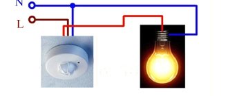
Connection diagram
You need to connect phase and zero to the input of the light sensor. From the point of exit, the phase goes to the load. This refers to a lantern that should turn on when night falls. The zero for the load should come from the machine or from the zero bus of the electrical panel.
In accordance with the installation rules, it is appropriate to make the connection in the junction box. It must have adequate tightness. This is due to the fact that in most cases the box is placed on the street near the spotlight. The most commonly used connection diagram is shown below:
Additionally, a starter may be needed. It is added to the circuit in cases where you need to turn on a fairly powerful street spotlight located on a pole. A device such as a magnetic starter tolerates inrush currents well, being designed for constant operation of the spotlight.
From this article you could learn how to properly connect a photo relay with your own hands. As you can see, all this work can be done independently without the relevant experience or skills, you just need to follow the diagrams!
Setup and calibration
When setting up the light sensor, it is important to use the black bag that comes with the sensor. This bag serves to simulate night.
Bag for setting up the light sensor
Of the adjustment controls in the light sensor, there is only a light level control (LUX). It sets the level at which the sensor's internal relay is triggered.
The level setting is described in more detail in the description of the circuit diagram below.
There are the simplest light sensors (for example, LXP-01), which have no adjustments at all. There are advanced ones that also have an on/off delay time regulator.
Well, now the most interesting thing -