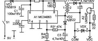
The symbol system for modern types of integrated circuits is established by OST 11073915-80. The notation system is based on an alphanumeric code.
The first element is a number indicating the group of the integrated circuit according to its design and technological design:
1,5,6,7 - semiconductor ICs; 2,4,8 - hybrid; 3 - other (film, vacuum, ceramic).
The second element is two or three digits (from 01 to 99 or from 001 to 999), indicating the serial number of the development of this series of ICs.
The first and second elements form a series of microcircuits.
The third element is two letters indicating the functional subgroup and type of microcircuit.
Computing devices:
BE - microcomputer; VM - microprocessors; BC - microprocessor sections; VU - microprogram control devices; VR - functional expanders; VB - synchronization devices; VN - interrupt control devices; BB - input-output control devices; VT - memory management devices; VF - functional information converters; VA - devices for interfacing with the highway; VI - timing devices; ВХ - microcalculators; VG - controllers; VK - combined devices; VZh - specialized devices; VP - others.
Fixed resistors
The name of constant resistors is associated with their nominal resistance, which remains unchanged throughout the entire period of operation. They differ depending on the design and materials.
Wire elements consist of metal wires. In some cases, high resistivity alloys may be used. The basis for winding the wire is a ceramic frame. These resistors have high nominal accuracy, but a serious drawback is the presence of a large self-inductance. In the manufacture of film metal resistors, a metal with high resistivity is sprayed onto a ceramic base. Due to their qualities, such elements are most widely used.
The design of carbon fixed resistors can be film or volumetric. In this case, the qualities of graphite as a material with high resistivity are used. There are other resistors, for example, integral ones. They are used in specific integrated circuits where the use of other elements is not possible.
19.Digital devices:
IR - registers; IM - adders; IL - half-adders; IE - counters; ID - decryptors; IR - combined; IV - encryptors; IA - arithmetic - logical devices; IP - others.
The fourth element is a number indicating the serial number of the development of the microcircuit in the series.
Additional symbols (from A to Z) can also be entered into the designation, defining the tolerances for variations in microcircuit parameters, etc. The first element of the designation may be preceded by the following letters: K - for equipment of wide application; E - for export (lead pitch 2.54 and 1.27 mm); P - plastic housing of the second type; M - ceramic, metal- or glass-ceramic body of the second type; E - metal-polymer housing of the second type; A - plastic housing of the fourth type; I - glass-ceramic body of the fourth type N - crystal carrier.
Symbols of foreign microcircuits according to the PRO ELECTRON system
Abroad, there are various coding systems (designations, markings) for ICs, operating both internationally and within individual countries or companies. In European countries, the IC coding system is similar to the system adopted for coding discrete semiconductor devices, and is used by semiconductor companies in various countries (England, Belgium, Italy, Spain, the Netherlands, Sweden, France, Germany, etc.). The basic principles of the coding system by which designations are assigned by the Association International Pro Electron are given below.
The code consists of three letters followed by a serial number (for example, TVA810, SAB2000, FLH101).
The first letter for single circuits reflects the principle of signal conversion in the circuit: S - digital; T - analog; U - mixed (analog-digital).
The second letter has no special meaning (selected by the manufacturer), with the exception of the letter H, which denotes hybrid circuits. For series (families) of digital circuits, the first two letters (FA, FB, FC, FD, FE, FF, FJ, FI, FL, FQ, FT, FY, FZ, GA, GB, GD, GF, GM, GT, GX , GY, GZ, NV, NS) reflect circuit-technological features, for example: FY - ESL series; FD, GD - MOS circuits; FQ - DTL circuits; GA - low-power TTL circuits; FL, GF - standard TTL circuits; GJ - high-speed TTL circuits; GM - low-power TTL circuits with Schottky diodes; NV - complementary MOS circuits of the 4000 A series; NS-complementary MOS circuits of the 4500 V series.
The third letter indicates the operating temperature range or, as an exception, another important characteristic: A - temperature range is not standardized; B - from 0 to + 70°C; C - from -55 to +125°C; D - from -25 to +70°С; E - from -25 to +85°C; F - from -40 to +85°С; G - from -55 to + 85°С.
This is followed by a serial number of at least four digits. If it consists of less than four digits, then the number of digits is increased to four by adding zeros in front of them.
In addition, the numbers may be followed by a letter to indicate a variant (variety) of the main type. Housing types can be designated by one or two letters. When designating housing options with two letters (after the serial number), the first letter reflects the design: C - cylindrical housing; D - with double-row parallel pin arrangement (DIP); E - powerful with a double-row arrangement of pins (with an external heat sink); F - flat (with double-sided pinout); G - flat (four-sided pin arrangement); K - TO-3 type body; M - multi-row (more than four rows); Q - with four-row parallel pin arrangement; R - powerful with a four-row pinout (with external heat sink); S - with single-row pin arrangement; T - with a three-row arrangement of pins. The second letter shows the case material: G - glass ceramics; M - metal; P - plastic; X - others.
Designations of housings with one letter: C - cylindrical; D - ceramic; F - flat; L—ribbon crystal holder; P - plastic DIP; Q - with a four-row arrangement of pins; T - miniature plastic; U - unpackaged IC.
In the code that was in force until 1973, the first two letters mean the same as in the modern one, and the third letter shows the functional purpose: A - linear amplification; B - frequency conversion/demodulation; C—oscillation generation; N - logical circuits; J - bistable or multistable circuits (frequency dividers, flip-flops, counters, registers); K - monostable circuits (one-shot); L — digital level converters (decoders, drivers); M - circuits with a complex logical configuration (for example, an adder); N - bistable or multistable circuits (with long-term storage of information); Q—random access memory (RAM); R—read-only memory (ROM); S—sense amplifier with digital output; Y - other schemes.
The first two digits that follow then indicate the serial number (from 10 to 99), and the third digit indicates the operating temperature range: 0 - temperature range is not standardized; 1 - from 0 to +70°C; 2 - from -55 to 125°C; 3 — from -10 to +85°С; 4 – from + 15 to +55°С; 5 — from -25 to +70°С; 6- from -40 to +85°C.
For example, IC type FY H121 is a digital logical IC (letter H) and belongs to the FY family (ESL). It is compatible with other ICs of this series (family), i.e. it is used at the same supply voltage, at the same input and output levels, and has the same performance. This is the third device in the series (number 12), operating in the temperature range from 0 to 70°C.
Letter designation of ICs of various companies
| Letter designation | Firm | Letter designation | Firm |
| A | RFT | DMPAL | N.S.C. |
| AD | Analod Devices (AD) | DMX | PMI |
| A.D.B. | National Semiconductor Corp. (NSC) | DN | Matsushita |
| D.P. | N.S.C. | ||
| ADC | NSC, Datel, Burr-Brown (BB), Hybrid Systems (HS) | DQ | SEEQ |
| D.S. | G.I., N.S.C. | ||
| ADD | N.S.C. | E | RFT, SGS |
| A.D.M. | N.S.C. | ECG | Sylvania |
| A.D.S. | N.S.C. | E.F. | Thomson |
| ADX | N.S.C. | EFB | Thomson |
| A.F. | N.S.C. | EFD | Thomson |
| A.H. | N.S.C. | EFF | Thomson |
| A.M. | Advanced Micro Devices (AMD), NSC, Raytheon, DSI | EFG EFH | Thomson Thomson |
| AMPAL | AMD | EFM | Thomson |
| AN | Matsushita | EFS | Thomson |
| ATF | BB | E.F.T. | Thomson |
| AY | General Instrument (GI) | EFY | Thomson |
| B | Fujitsu, R.F.T. | EFZ | Thomson |
| B.A. | Rohm | EL | Elcap |
| Bt | Brooktree Corp. | E.P. | Altera |
| BUF | Precision Monolithics Inc. (PMI) | ER ESM | G.I. Thomson |
| C | NSC, Fujitsu, RFT | ET | Thomson |
| C.A. | RCA | ETC | Thomson |
| CCD | Fairchild | ETL | Thomson |
| CD | RCA, NSC | F | Fairchild, Master Logic (ML) |
| CDA | Thomson | F.C. | Mullard |
| CDM | RCA | FCH | Valvo |
| CDP | RCA | FCK | Valvo |
| CF | Harris | FCL | Valvo |
| C.M. | Solitron, Mitel | FCM | Fairchild |
| CMP | PMI | FCY | Valvo |
| COM | SMC | FD | RTC, Siemens |
| COP | N.S.C. | FDN | Valvo |
| C.P. | G.I. | FDQ | Valvo |
| CRT | SMC | FDR | Valvo |
| C.S.C. | Crystal Semiconductor | F.E. | RTC |
| C.S. | Cherry Semiconductor Corp. | F.E.J. | Valvo |
| C.U. | G.I. | FEY | Valvo |
| CX | Sony | FF | RTC |
| CXA | Sony | FGC | Fairchild |
| C.Y. | Cypress Semiconductor | FGE | Fairchild |
| D | Corp. RFT, Intersil, Siliconix | FJ FK | Mullard, RTC Mullard |
| DA-AD | N.S.C. | FL | Siemens |
| DAC | BB, Datel, PMI, HS, NSC, Raytheon | FLT FQ | DSI SGS |
| DAS | Datel | F.W.A. | Fairchild |
| DAX | N.S.C. | FX | Consumer Microcircuits Limited |
| DC | Digital Equipment Corp. (DEC) | FY | Siemens |
| DCJ | DEC | FZ | Siemens |
| DE | SEEQ | FZH | Valvo |
| DF | Siliconix | FZJ | Valvo |
| DG | Intersil, Siliconix | FZK | Valvo |
| DGM | Siliconix | FZL | Valvo |
| D.H. | N.S.C. | G | Siliconix, Intersil |
| D.I. | Dionics | GA | Mostek |
| D.L. | GI, RFT | GAP | PMI |
| DM | NSC, SEEQ | G.B. | Mostek |
Letter designation of ICs of various companies (continued)
| Letter designation | Firm | Letter designation | Firm |
| G.D. | Siemens | IRK | Sharp |
| G.E. | General Electric (GE) | ISP | N.S.C. |
| GEIC | G.E. | ITT | ITT |
| GF | RTC | IX | Intel |
| G.L. | GSS | J | Matsushita |
| GT | RTC | JBP | Texas Instruments (TI) |
| GX | Siemens, Valvo | K.A. | Samsung |
| GXB | Philips, RTC, Valvo | K.B. | G.I. |
| GZ | RTC | K.M. | Samsung |
| GZF | Valvo | KR | SMC |
| H | Hughes, SGS, Siliconix | KS | Gold Star, Samsung |
| H.A. | Harris, Hitachi | L | SGS, Siliconix |
| HAB | Harris, RTC, Valvo | L.A. | Sanyo, G.I. |
| HAL | Monolithic Memories (MMI) | LAS | Lambda |
| HAS | AD | LB | Sanyo |
| H.B.S., H.B.F. | SGS | L.C. | GI Sanyo |
| HC | Harris, Honeywell, RCA | LD | Siliconix |
| HCC | SGS | L.E. | Sanyo, Seeq |
| HCF | SGS-ATES | LF | N.S.C. |
| HCMP | Hughes | LFT | N.S.C. |
| HD | Harris, Hitachi | LG | G.I. |
| HDS | AD | L.H. | NSC, Raytheon, Sharp, Siliconix |
| HE | Honeywell | L.L.M. | Lambda |
| HEF | Mullard, Philips, RTC, Valvo | L.M. | NSC, Raytheon, Sanyo, Seeq, Siliconix, Signetics |
| HI | Harris | ||
| HLCD | Hughes | LMC | Lambda |
| H.M. | Harris, Hitachi | LNA | TRW |
| HMCS | Hitachi | LP | N.S.C. |
| HMMP | Hughes | LPD | Lambda |
| HN | Hitachi | L.Q. | Seeq |
| HNVM | Hughes | LR | Sharp |
| HPL | Harris | L.S. | SGS |
| HPROM | Harris | LT | Linear Technology Corp. |
| HRAM | Harris | LTT | Lighes Telegraphiques Telefoniques |
| HROM | Harris | L.U. | Sharp |
| H.S. | Harris, Hybrid Systems NSC | LZ | Sharp |
| HSG | SGS | M | Matsushita, Mitsubishi, SGS, Thomson |
| HSSR | Hughes | ||
| HSO | RTC | M.A. | Mitel. Philips |
| HT | Harris, Honeywell | MAA | ITT, Tesla |
| HX | Philips | MAB | Tesla |
| HXA | RTC | MAC | Tesla |
| HY | N.S.C. | MAF | Tesla |
| I.B. | Intel | M.A.S. | Tesla |
| IC | Intel | MAT | PMI |
| ICL | Intersil | Max | Maxim |
| ICM | Intersil | M.B. | Fujitsu, Intel, Philips |
| ID | Intel | MBA | Tesla |
| IDM | N.S.C. | MBL | Fujitsu |
| IH | Intersil, N.S.C. | M.B.M. | Fujitsu |
| I.M. | Intel, Intersil, NSC | M.C. | Intel, Motorola, Nippon Electric (NEC), Unitra |
| IMI | International Microcircuits Inc. (IMI) | M.C.A. | NSC, Tesla |
| IMP | N.S.C. | MCB | Motorola |
| IMS | Inmos | MCBC | Motorola |
| INS | N.S.C. | MCC | Motorola |
| IP | Intel | MCCF | Motorola |
| IPC | N.S.C. | M.C.E. | Motorola, M.C.E. |
| IR | Sharp | MCM | Motorola |
Letter designation of ICs of various companies (continued)
| Letter designation | Firm | Letter designation | Firm |
| MCX | Unitra | NOM | Plessey |
| MCY | Unitra | N.S. | Nitron |
| M.D. | Intel, Mitel, Philips | N.S.C. | N.S.C. |
| MDA | Tesla | NSL | N.S.C. |
| M.E. | Philips | OP | PMI |
| M.E.A. | Milliard | OPA | BB |
| MEB | Philips | PA | RCA |
| MEM | G.I. | PAL | MMI, NSC |
| MEN | G.I. | ||
| M.F. | N.S.C. | PC | G.I. |
| MGB | M.C.E. | PCA | Philips, Valvo |
| M.G.C. | M.C.E. | PCB | Milliard, Philips, Valvo |
| M.H. | NSC, Mitel, Tesla | ||
| M.H.A. | Tesla | PCC | Philips, Valvo |
| MHC | Tesla | PCD | Milliard, Philips, Valvo |
| M.H.D. | Tesla | P.C.E. | Philips, Valvo |
| MHE | Tesla | PCF | Milliard, Philips, Valvo |
| MHF | Tesla | PIC | GI, Unitrode |
| MHG | Tesla | PKD | PMI |
| MHW | Motorola | PLE | Monolithic Memories |
| MIC | ITT | P.M. | PMI |
| MJ | Plessey | P.M.B. | T.I. |
| M.J.A. | Tesla | PMJ | T.I. |
| M.J.B. | Tesla | P.N.A. | Philips, Valvo |
| MK | Mostek | PMR | Lambda |
| MKB | Mostek | R | Raytheon, Rockwell |
| MKJ | Mostek | R.A. | GI, Reticon |
| M.L. | M.L., Mitel, Plessey | R.C. | Raytheon, Reticon |
| M.L.A. | M.L. | REF | PMI |
| MLM | Motorola | R.L. | Raytheon, Reticon |
| MM | Intel, N.S.C. | R.M. | Raytheon |
| MMS | Motorola | R.O. | GIC, Reticon |
| MN | Matsushita, Micro Networks, Plessey | RPT | PMI |
| RV | Raytheon | ||
| MP | Intel, MPS, Plessey | R5 | Reticon |
| MPC | BB | R6 | Hybrid Systems |
| MPOP | MPS | S | American Microsystems, Signetics, Siliconix |
| MPU | SMC | ||
| MPY | IMI | S.A. | Signetics |
| MPREF | MPS | SAA | Milliard, RTC, Philips, Valvo |
| MSL | Oki | ||
| M.S.M. | Oki | S.A.B. | Philips, RTC, Telefunken, Valvo |
| M.T. | Mitel, Plessey | ||
| MUX | GI, PMI | S.A.D. | Reticon |
| MV | DSI, Plessey | SAF | Philips, RTC, Valvo |
| MWS | RCA | SAH | Milliard |
| MX | American Microsystems, DSI, Intel | S.A.J. | ITT, Siemens, Valvo |
| S.A.K. | ITT, Valvo | ||
| MYA | Tesla | SAM | Reticon |
| MZH | Tesla | SAS | Telefunken, Oki |
| MZJ | Tesla | SAY | ITT |
| MZK | Tesla | S.B.A. | G.I. |
| N | Signetics | SBB | Philips, Valvo |
| NC | GI, Nitron | SBP | Texas Instruments (TI) |
| NCR | NCR Microelectronics | S.C. | Nitron |
| NE | Signetics | SCB | Signetics |
| N.H. | N.S.C. | sec | Signetics |
| NJ | Plessey | SCL | SSS |
| NMC | N.S.C. | SCM | SSS |
| NMH | N.S.C. | SCN | Signetics |
Letter designation of ICs of various companies (continued)
| Letter designation | Firm | Letter designation | Firm |
| sex | N.S.C. | TBC | Siemens |
| SD | N.S.C. | TBE | Siemens |
| S.D.A. | Siemens, Philips, Thomson | TBP | T.I. |
| S.E. | Signetics | TC | Toshiba |
| SF | Thomson | TCA | ITT, Siemens, Valvo, SGS, Philips, RTC, Thomson, Telefunken |
| SFC | Thomson | ||
| SFF | Thomson | ||
| S.G. | Silicon General | TCD | Toshiba |
| SH | Fairchild | TCP | Toshiba |
| SHC | BB | T.D. | Toshiba, Thomson |
| S.H.M. | DSI | TDA | ITT, RTC, SGS, Philips, Siemens, Telefunken, Thomson, Valvo |
| S.I. | Siliconix | ||
| SL | GI, NSC, Plessey | ||
| SLE | Siemens | TDB | Philips, RTC, Siemens, Thomson, Valvo |
| S.M. | NSC, SSS | ||
| SMB | T.I. | TDC | TRW, Siemens, Thomson, Transitron |
| SMM | Suwa | ||
| SMP | PMI | TDE | Thomson, R.T.C. |
| SN | TI, Monolithic Memories | TDF | Thomson |
| SNA | T.I. | TDP | Toshiba |
| SNB | T.I. | TDS | TRW |
| SNC | T.I. | T.E. | Thomson |
| SND | SSS | TEA | RTC, Philips, Valvo, Mullard, Thomson |
| SNH | T.I. | ||
| SNJ | T.I. | TEB | Thomson |
| SNN | T.I. | TEC | Thomson |
| SNS | T.I. | TEE | Thomson |
| SNT | T.I. | T.F.A. | Siemens |
| SP | American Microsystems | TFF | Transitron |
| SPB | G.I. | TG | Transitron |
| SPR | G.I. | TIFPLA | T.I. |
| S.R. | SMC | TIL | T.I. |
| SRM | Suwa | TIBPAL | T.I. |
| ss | GI, SSS | TL | TI, Telefunken |
| SSI | SSI | TLC | T.I. |
| sss | PMI | TLE | Siemens |
| STK | Sanyo | TM | Toshiba, Telmos |
| S.U. | Signetics | TMC | Transitron, TRW |
| SVM | Suwa | TMD | Telmos |
| S.W. | PMI | TMF | Telmos |
| S.Y. | Synertek | TML | Telmos |
| SYE | Synertek | TMM | Toshiba |
| SYM | Synertek | TMP | Toshiba |
| SYX | Synertek | TMS | T.I. |
| T | SGS, Toshiba | TMZ | TRW |
| T.A. | RCA, Toshiba | TNF | Transitron |
| TAA | ITT, Siemens, SGS, Teleunken, Philips, Mullard, Valvo | TOA | Transitron |
| TP | NSC, Teledyne | ||
| T.Q. | TQSI | ||
| TAB | Mullard | TRC | Transitron |
| TAC | T.I. | T.S.C. | Teledyne |
| TAD | Mullard, Reticon | TSR | Transitron |
| T.A.E. | Siemens | TT | DSI |
| TAF | Siemens | TVR | Transitron |
| TAL | T.I. | U | Telefunken, GI, RFT |
| TAT | T.I. | U.A. | G.I. |
| T.B.A. | ITT, RTC, Mullard, SGS Siemens, Philips, Telefunken, Valvo | UAA | Telefunken, Thomson, Valvo |
| UAB | Thomson | ||
| TBB | Siemens | UAC | Thomson |
Letter designation of ICs of various companies (continued)
| Letter designation | Firm | Letter designation | Firm |
| U.C. | Unitra, Unitrode, Solitron | VI | DSI |
| UCN | Spraque | VL | VLSI Technology |
| UCP | Spraque | VR | DSI |
| UCQ | Spraque | VS | VLSI Technology |
| UCS | Spraque | VT | VLSI Technology |
| UCX | Unitra | VU | VLSI Technology |
| UDN | Spraque | W | Siliconix |
| UDP | Spraque | W.D. | Western Digital |
| UDS | Spraque | X | Xicor |
| UGN | Spraque | XR | Exar |
| UHN | Spraque | Z | SGS, Zilog |
| UL | American Microsystems, Unitra | ZLD | Ferranti |
| ZN | Ferranti | ||
| ULN | Spraque | ZNA | Ferranti |
| ULS | Spraque | ZNREF | Ferranti |
| UTN | Spraque | ZSS | Ferranti |
| ZST | Ferranti | ||
| ZX | Zytrex | ||
| ZXCAL | Zytrex | ||
| 9N | Fairchild | ||
| 10G | Gigabit Logic Inc. (GLI) | ||
| V.C. | VLSI Technology | 11G | GLI |
| VF | VLSI Techn., DS1 | 12G | GLI |
| VFC | BB | 16G | GLI |
| VH | VLSI Technology | 90G | GLI |
Capacitors
A capacitor is a system that includes two or more electrodes made in the form of plates - plates. They are separated by a dielectric, which is much thinner than the capacitor plates. The entire device has mutual capacitance and has the ability to store electrical charge. In the simplest diagram, the capacitor is presented in the form of two parallel metal plates separated by some kind of dielectric material.
On the circuit diagram, next to the image of the capacitor, its nominal capacitance is indicated in microfarads (μF) or picofarads (pF). When designating electrolytic and high-voltage capacitors, after the rated capacitance the value of the maximum operating voltage, measured in volts (V) or kilovolts (kV), is indicated.
Diodes and Zener diodes
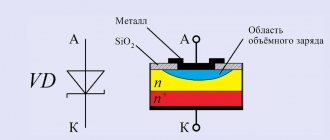
Diodes are the simplest semiconductor devices that operate on the basis of an electron-hole junction known as a pn junction. The property of one-way conductivity is clearly conveyed in graphic symbols. A standard diode is depicted as a triangle, symbolizing the anode. The apex of the triangle indicates the direction of conduction and abuts the transverse line indicating the cathode. The entire image is intersected in the center by an electrical circuit line.
The letter designation VD is used to mark diodes. It displays not only individual elements, but also entire groups, for example, diode bridges. The type of a particular diode is indicated next to its position designation.
The basic symbol is also used to designate zener diodes, which are semiconductor diodes with special properties. The cathode has a short stroke directed towards the triangle, symbolizing the anode. This stroke is positioned unchanged, regardless of the position of the zener diode icon on the circuit diagram.
Transistors
Most electronic components have only two terminals. However, elements such as transistors are equipped with three terminals. Their designs come in a variety of types, shapes and sizes. Their general principles of operation are the same, and minor differences are associated with the technical characteristics of a particular element.
Transistors are used primarily as electronic switches to turn various devices on and off. The main convenience of such devices is the ability to switch high voltages using a low voltage source.
At its core, each transistor is a semiconductor device with the help of which electrical oscillations are generated, amplified and converted. The most widespread are bipolar transistors with the same electrical conductivity of the emitter and collector.
In the diagrams they are designated by the letter code VT. The graphic image is a short dash with a line extending from the middle of it. This symbol indicates the base. Two inclined lines are drawn to its edges at an angle of 60, displaying the emitter and collector.
The electrical conductivity of the base depends on the direction of the emitter arrow. If it is directed towards the base, then the electrical conductivity of the emitter is p, and that of the base is n. When the arrow is directed in the opposite direction, the emitter and base change their electrical conductivity to the opposite value. Knowledge of electrical conductivity is necessary to correctly connect the transistor to the power source.
In order to make the designation on the diagrams of radio components of the transistor more clear, it is placed in a circle indicating the housing. In some cases, a metal housing is connected to one of the terminals of the element. Such a place on the diagram is displayed as a dot placed where the pin intersects with the housing symbol. If there is a separate terminal on the case, then the line indicating the terminal can be connected to a circle without a dot. Near the positional designation of the transistor its type is indicated, which can significantly increase the information content of the circuit.
