To ensure normal operation of electrical installations and protect operating personnel from electric shock, grounding is used. If there is no or incorrectly installed grounding system, the risk of equipment failure and electric shock increases. According to regulatory documentation, all electric motors must be grounded. The housing is connected to the grounding system using a conductor connected to the ground loop. The exception is for motors mounted on a metal base, which are grounded through the frame or have contact with the ground through metal pins. In this article we will tell readers of the Sam Electric website how grounding of electric motors is carried out according to the PUE and what else is important to know about this event.
Grounding the electric motor according to the PUE
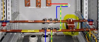
According to the PUE, the engine is grounded with a separate conductor. In this case, series connection of electric motors with the circuit is prohibited, as shown in the diagram below:
If the circuit is damaged, electric motors connected after the break become potentially dangerous due to lack of grounding. There is a danger of equipment failure. And incorrect operation of the protection exposes personnel to danger. Therefore, such a connection is unacceptable.
Why is it important to find and correct a bad ground in a car?
A poor engine ground can ultimately prevent the battery from charging properly, receiving signals from the computer correctly, causing the headlights to glow abnormally, causing starting problems and other problems.
Moreover, poor motor grounding can also cause damage. If too much current tries to find the correct ground without success, it will take the easy path through transmission components, transmission cable, throttle cable, wheel bearings, causing severe damage to these and other components.
Whenever you see signs of electrical problems, check the motor ground.
The diagnostic tests described here are simple procedures that you can perform using a digital multimeter. And they'll save you time and money in minutes.
Motor grounding
Installation of an electric motor, according to all norms and regulations, requires grounding work. To do this, calculate the current resistance that passes from the engine to the ground.
After completing installation of the equipment, resistance measurements are taken, and based on the data obtained, the number of grounding elements is determined.
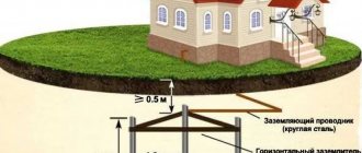
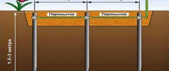
Metal rods are welded to the grounding of the electric motor and deepened into the ground 50 cm. Connecting elements, electric conduits, are connected in parallel. The grounding loop is made around the perimeter so as to cover the engine.
Grounding and grounding: what is the difference
This is what improper installation of protective grounding can lead to
What is the difference between grounding and grounding: generalization
Grounding differs from grounding in the method of protection and installation. Such systems contradict each other, which means installing a circuit that includes both options is unacceptable. Zeroing is installed only in apartment buildings that are not equipped with their own circuit. In other cases, such installation is prohibited. Now let's talk in more detail about the methods of its construction.
Who should do grounding in an apartment building - portal about housing and communal services
Having received a choice, the released current passes to the alloys. The soil where they lead perfectly absorbs energy. The current “spreads” especially well in the aquifers of the earth.
Expert opinion
It-Technology, Electrical power and electronics specialist
Ask questions to the “Specialist for modernization of energy generation systems”
Stages of self-grounding The charge from the last one began to smoothly flow down the spire, just as before a thunderstorm the current flows down the masts of ships and church spiers. Ask, I'm in touch!
The principle of calculating the resistance of grounding conductors
There are quite a few ways to calculate the characteristics of the main grounding elements, but the main parameter for such calculations is the same - the resistance indicator. Its optimal value is determined using data from the normative regulation of the PUE. It is impossible to implement reliable protective grounding of an object without calculating the resistance of its main elements.
For example, it is necessary to determine the grounding resistance for electrical equipment with voltages over 1 kW, with an isolated neutral. In accordance with the profile data of the documentation PUE 1.7.96, it is necessary to use the formula R≤250/I, where:
5.3.58
Minimum voltage protection must be installed in the following cases:
for DC electric motors that do not allow direct connection to the network;
for electric motors of mechanisms whose self-starting after shutdown is unacceptable due to process conditions or safety conditions;
for some other electric motors in accordance with the conditions given in 5.3.52.
For critical electric motors that require self-starting, if they are turned on using contactors and starters with a holding winding, mechanical or electrical time delay devices must be used in the control circuit to ensure that the electric motor is turned on when the voltage is restored within a specified time. For such electric motors, if this is permissible under the conditions of the technological process and safety conditions, it is also possible to use switches instead of control buttons so that the circuit of the holding winding remains closed in addition to the auxiliary contacts of the starter and this ensures automatic reverse switching when the voltage is restored, regardless of the time of the power interruption.
Grounding switches
1.Natural
- water pipes laid in the ground (HW)
- metal building structures and foundations securely connected to the ground
- metal cable sheaths
— casing pipes for artesian wells
— gas pipelines and pipelines with flammable liquids
— aluminum shells of underground cables
— pipes of heating mains and hot water supply
The connection to the natural ground electrode must be in at least two different places.
Artificial
Contour
Remote: group and single
Allows you to choose a place with minimal soil resistance.
Traditionally, for artificial grounding conductors, angle steel with a flange thickness of at least 4 mm, steel strips with a thickness of at least 4 mm, or bar steel with a diameter of 10 mm or more are used.
Recently, deep-seated grounding electrodes with copper-plated or galvanized electrodes have become widespread, which are significantly superior to traditional methods in terms of durability and cost of manufacturing the grounding electrode.
A special problem is the creation of high-quality grounding in permafrost conditions. Here it is worth paying attention to electrolytic grounding systems that can effectively solve the problem.
Detailed information about various sealing schemes, calculation methods and consultations can be obtained on the website www.zandz.ru
Installation rules
Now, regarding the wiring of grounding conductors. They can be carried out on concrete and brick structures, both in the horizontal and vertical planes. Fastening to structures is done with dowels, between which you can leave a distance:
- on straight sections in the range of 600-1000 mm;
- on bends and turns no more than 100 mm.
The distance from the floor base to the fastening point should be 400-600 mm. If the grounding system of conductors will be laid in wet rooms, then under them it will be necessary to lay pads with a thickness of at least 10 mm.
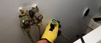
Motor grounding requirements
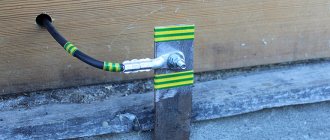
According to the requirements and rules, the installed electric motor must be grounded before starting. An exception is those cases in which the motor housing is mounted on a metal support connected to the ground through the metal structure of the building or through a grounding conductor. In other cases, the motor housing must be connected by wire to the grounding loop of the building, made of a strip of metal by welding.
This is a working ground.
Otherwise, if the insulation between the motor winding or conductor and the motor housing is broken, the protective device will not operate and will not turn off the power. And the engine will continue to work. Each electrical machine must have an individual connection to the ground electrode. Series connection of electric motors with a ground loop is prohibited, because if one of the connections to the ground electrode is broken, the entire circuit will be isolated from the ground. To install protective grounding, it is necessary to have an additional grounding conductor in the power cable, one end of which is connected to the terminal box of the electric motor, and the other to the housing of the motor control cabinet. The electrical cabinet must first be connected to ground. In the event of a breakdown between the current conductor and this grounding conductor, a short circuit current is generated, which will open the protective or switching device (thermal or current relay, circuit breaker). The cross-section of the grounding conductor that meets the requirements of the Electrical Installation Rules is given in Table 1:
| Section of phase conductors, mm2 | Minimum cross-section of protective conductors, mm2 |
| S≤16 | S |
| 16 35 | S/2 |
The cross-section of phase conductors is calculated based on the current load of the consumer.
Grounding device
Grounding device - a system consisting of a grounding loop and conductors that ensure the safe passage of current through the ground. Based on the Electrical Installation Rules, natural grounding conductors can be:
- Building frames (reinforced concrete or metal) that are connected to the ground.
- Protective metal braiding of cables laid in the ground (except aluminum)
- Pipes of wells, water pipelines laid in the ground (except for pipelines with flammable liquids, gases, mixtures)
- Supports of high-voltage power lines
- Non-electrified railway tracks (subject to welded rail connections)
For artificial grounding conductors, according to the rules, unpainted steel rods (with a diameter of more than 10 mm), a corner (with a flange thickness of more than 4 mm), and sheets (with a thickness of more than 4 mm and a cross-section of more than 48 mm2) are used. To create a system with artificial grounding, metal rods, corners or sheets with the thickness and cross-section indicated above, but at least 2.5 m long, are dug or driven into the ground near the structure. Then they are welded together using rod or sheet steel. This structure must be located more than 0.5 m from the ground surface. According to the requirements, the building's grounding loop must have at least two connections to the ground electrode. Depending on the purpose, equipment grounding is divided into two types: protective and operational. Protective grounding serves for the safety of personnel and prevents the possibility of electric shock to a person due to accidental contact with the electrical installation housing. The enclosures of electrical installations and electrical machines that are not fixed to “solidly grounded” supports, electrical cabinets, metal boxes of distribution boards, metal hoses and pipes with power cables, and metal braids of power cables are subject to protective grounding. Working grounding is used in the case when, for production reasons, in the event of insulation damage and breakdown to the housing, continued operation of the equipment in emergency mode is required. In this way, for example, the neutrals of transformers and generators are grounded. Also, working grounding includes connecting lightning rods to the general grounding network, which protect electrical installations from direct lightning strikes.
According to the Electrical Installation Rules, electrical networks with a rated voltage of over 42 V for alternating current and over 110 V for direct current must be grounded.
Appendix: project in DWG and PDF formats
Files in DWG and PDF formats are available for downloading only to authorized users.
Do you need to complete a grounding and lightning protection project? Order it by contacting the ZANDZ.ru Technical Center!
Still have questions about this calculation? Ask it in the comments to this page!
Grounding systems
Introduction.
Grounding is one of the main factors providing protection against electric shock. In accordance with Chapter 1.7 of the PUE, all grounding systems for electrical installations can be divided into two groups:
- systems with solidly grounded neutral these include the TN grounding system (which in turn is divided into TN-C, TN-CS, TN-S systems) and the TT grounding system
- systems with isolated neutral, these include the IT grounding system
The first letter of the abbreviation indicates the nature of the grounding of the power source, and the second - the nature of the grounding of the open conductive parts of the power receiver:
- T (from the French terre - earth) - grounded;
- N (from the French neutre - neutral) - connection to the neutral of the power source (grounding);
- I (from the French isolé - isolated) - isolated from grounding.
The article also contains the following abbreviations:
- N - functional (working) zero - neutral conductor used to connect an electrical receiver.
- PE - protective zero - a protective conductor designed for grounding electrical equipment housings.
- PEN is a conductor that combines the functions of zero protective and zero working conductors.
Now we will analyze in detail the listed types of grounding systems.
TN grounding system
The TN system is a system in which the neutral of the power source is solidly grounded, and the open conductive parts of the electrical installation are connected to the solidly grounded neutral of the power source through neutral protective conductors (clause 1.7.3. PUE).
As already written above, the TN system is divided into the following systems (subsystems): TN-C, TN-CS, TN-S.
2.1 TN-C grounding system
The TN-C system is a TN system in which the neutral protective and neutral working conductors are combined in one conductor along its entire length. That is, with this system, a common PEN conductor is used, which is used both to connect electrical receivers and to ground their open conductive parts (cases).
TN-C grounding system diagram:
As can be seen in the diagram, with this system, the current-carrying housings of electrical equipment are grounded, this is necessary so that when a phase wire is shorted to the housing of the electrical receiver, due to its breakage or damage to the insulation, a short circuit occurs, which, in turn, would lead to the activation of protective equipment (circuit breaker) and power outage.
The main disadvantage of the TN-C system is the loss of its protective functions in the event of a burnout (break) of the PEN conductor, while a life-threatening electrical potential may arise on the grounded electrical equipment housing.
Due to the insufficient degree of protection, this system is not currently used, but it is still found in older buildings. When reconstructing old buildings, the TN-C grounding system is replaced with a TN-CS or TN-S system.
Standards Standards for the design of grounding networks - download for free
R.N. KARYAKIN
Doctor of Engineering sciences, professor
STANDARDS FOR CONSTRUCTION OF GROUNDING NETWORKS
MOSCOW
Energoservice
2002
Doctor of Technical Sciences, Professor K aryakin Rudolf Nikolaevich
The standards apply to grounding devices of electrical installations with voltages up to 1 kV and higher. This 3rd edition of the Standards, being a technological addition to Chapter 1.7 “Grounding and protective measures for electrical safety” of the Electrical Installation Rules (PUE), meets the requirements of the standards of the International Electrotechnical Commission (IEC): 60364-5-54-2001: Earthing protective arrangements conductors and eq u ipotential bonding and 61024-1-2001: Protection of structures against fire, explosion and life hazards (Lightning Protection).
Compared to the previous 2nd edition, the volume of the book has been more than doubled due to the addition of new regulatory materials.
The book is addressed to engineers (electrical engineers, electric power engineers, electrical installers, builders), foremen, foremen, technicians, electrical workers involved in the design, installation, testing, certification, energy supervision, repair, reconstruction and operation of electrical installations.
PREFACE TO THE 3RD EDITION
This 3rd edition of the Standards for the Construction of Grounding Networks is intended as a technological
continuation of Chapter 1.7 “Grounding and protective electrical safety measures” of the Electrical Installation Rules (PUE).
That is why the Standards require their practical application simultaneously
with the PUE in a single process of creating electrical installations and lightning protection of buildings and structures: design - ordering equipment and materials - installation - commissioning and acceptance tests - certification.
Compared to the previous 2nd edition, the volume of the book has been more than doubled by adding additional regulatory requirements for grounding and lightning protection networks, taking into account new standards of the International Electrotechnical Commission (IEC): 60364-5-54-2001: Earthing arrangements protective conductors and equipotential bonding and 61024-1-2001: Protection of structures against fire, explosion and life hazards (Lightning Protection).
The author expresses gratitude to Eng. A.S. E rmolenko for his great help in preparing the 3rd edition of the manuscript for publication.
Author
Moscow
October 29, 2001
FROM THE PREFACE TO THE 1ST EDITION
In contrast to the well-known instructional materials on the construction of grounding networks and lightning protection, the proposed Standards comply with the Basic Rule for the Construction of Electrical Installations
(see Chapter 1, clause 1.1.) and the set of standards GOST R 505 71 (M EK 364), according to which grounding or grounding of open conductive parts of electrical installations should be carried out:
1) at a rated voltage of more than 50 V AC or more than 12 0 V DC - in all electrical installations;
2) at rated voltages above 25 V AC or above 60 V DC - in areas with increased danger, especially dangerous ones and in outdoor electrical installations.
For comparison, let us recall that according to well-known instructional materials, grounding or grounding of electrical installations is carried out:
1) at a voltage of 380 V and above alternating current and 440 V and above direct current - in all electrical installations;
2) at rated voltages above 42 V AC and above 110 V DC - only in areas with increased danger, especially dangerous ones and in outdoor stops.
The standard is supplemented by standard methods for calculating grounding and protective conductors and a modern classification of grounding systems for electrical installations with voltages up to 1 kV. The terminology used in the book in the field of design of grounding networks has been clarified and supplemented in accordance with the set of standards GOST R 50571 (IEC 364).
The author considers it his pleasant duty to express gratitude to his colleagues, Ph.D. t echn. Science V.I. Solntseva and engineer. OK. Konovalova for her assistance in preparing a number of paragraphs.
https://www.youtube.com/watch?v=XLWD0-jxrpA
The author thanks Eng. A.S. Ermolenko for assistance in preparing the manuscript for publication.
Author
Moscow
September 1, 1999
INTRODUCTION
The Electrical Installation Rules in force in 2001 (PUE - 6th edition) quite clearly regulate the requirements for protective measures depending on the values of rated voltages. According to the PUE, it is required to ground or neutralize electrical installations:
1) at a voltage of 380 V and above alternating current and 440 V and above direct current - in all electrical installations;
2) at rated voltages above 42 V, but below 380 V AC and above 110 V, but below 440 V DC - only in areas with increased danger, especially dangerous ones and in outdoor installations.
Grounding or grounding of electrical installations is not required at rated voltages up to 42 V AC and up to 11 0 V DC in all cases except hazardous areas and electric welding installations.
Recommendations of the PUE - 6th ed. do not ensure electrical safety both indoors and in areas where outdoor electrical installations are located.
To ensure electrical safety in accordance with the IEC 364-4-41-1992 standard, it is necessary to ground or neutralize electrical installations:
1) at a rated voltage of more than 50 V AC (rms value) or more than 120 V DC (rectified) - in all electrical installations;
2) at rated voltages above 25 V AC (rms value) or above 60 V rectified current - only in areas with increased danger, especially dangerous ones and in outdoor electrical installations.
Grounding or grounding of electrical installations is not required at rated voltages up to 25 V AC or up to 60 V rectified current in all cases except hazardous areas and electric welding installations.
Table
B.
_
1
| Regulatory document | Requirements | Premises | |
| No increased danger | with increased danger | especially dangerous | |
| PUE - 6 and building. | Grounding or grounding is required | Rated voltage 380V or above AC or 440V or above DC | When rated voltage is higher than 42V AC or higher than 110V DC |
| No grounding or grounding required | When the rated voltage is below 380 V AC or below 440 V DC | At rated voltages up to 42 V AC or up to 11 0 V DC in all cases except hazardous areas and electric welding installations | |
| Recommendations IEC 364-4-41 (1992) | Grounding or grounding is required | When rated voltage is more than 50 V AC or more than 120 V DC | When rated voltage is higher than 25 V AC or higher than 60 V rectified current |
| No grounding or grounding required | With a nominal voltage of 50 VAC and below or 120 VDC and below | At rated voltages up to 25 V AC or up to 60 V rectified current in all cases except hazardous areas and electric welding installations | |
| Protection from direct contact by guards or enclosures or insulation is not required if the electrical equipment is within the range of the potential equalization system | At a rated voltage not exceeding 25 VAC or 60 VDC | At a rated voltage not exceeding 6 V AC or 15 V rectified current | |
| No protection from direct contact with third-party conductive parts that may be live is required. | At a voltage not exceeding 25 V AC or 60 V rectified current | At a voltage not exceeding 6 V AC or 15 V rectified current |
Well pump kit
Let's look at the encountered (recommended) submersible well pump kit. Typically this kit includes:
- The pump itself. It is often sold separately;
- Electrical cable for connection. Included in the pump kit;
- Automation block. Sold as a set or as additional equipment;
- Hydraulic accumulator (expansion tank). Sold as additional equipment.
The given equipment for a well pump is the maximum and is not typical for all manufacturers of well pumps. The automation unit (control system) and hydraulic accumulator may not be included in the kit and their need is determined by the water supply scheme of the house. In the simplest version, the well pump is equipped only with an electrical cable for connection.
Understanding this, let's consider three options for connecting a well pump.
- Connecting a well pump to power supply without automation;
- Connecting the well pump to the power supply with the control unit (system) (automation unit);
- Connecting the well pump to the power supply via a pressure switch.
What needs to be grounded in the cable?
According to the PUE (Electrical Installation Rules), the metal armor of the cable, as well as any other metal non-current-carrying parts of electrical installations, must be reliably grounded. Together with the armor and metal shielding braids of power cables, the following must be grounded:
- metal trays;
- metal boxes and channels;
- pipes;
- load-bearing cables;
- other supporting metal structures
The main function of grounding cable armor and supporting structures along which power lines are laid is to protect a person from electric shock in the event of a breakdown of electrical insulation. In addition, grounding the cable armor is an important condition for the proper operation of relay protection against ground faults.
When laying long cable lines, it is not always possible to get by with just one piece of cable. In such cases, cable couplings are used to connect cable sections. If the protective sheath of the cable sleeve is made of metal, then it must also be grounded.
Checking weight in a car
Transmissions on some vehicle models are equipped with a chassis or protective shield for modules, sensors, and solenoids (relays). You can also test these grounds using your digital multimeter.
- Check the voltage drop between the transmission and the negative terminal of the battery. The voltage drop should be 0.2V or lower.
- Check individual chassis grounding by checking the voltage drop across each ground terminal on the transmission. The voltage drop should be 0.2V or lower.
Clean, repair or replace the transmission ground as necessary. Remove grease, rust and paint from ground terminals or replace damaged ground straps.
General Voltage Drop Values
Choke cables and other equipment can be damaged when high electrical current cannot find the correct path back to ground.
How does a centrifugal pump with an electric motor work?
The diagram below shows the structure of the internal part of a centrifugal pump and its connection to an electric motor. In the body, pos. 1, which has the shape of a snail, contains an impeller, and blades are located on it. These elements are located on the motor shaft. The suction and pressure pipelines are connected to the discharge and inlet openings. The water that fills the pump, under the action of the centrifugal force arising from the rotation of the impeller by its blades, is thrown into the pressure pipeline from the housing. When the impeller rotates, a vacuum is created in the suction pipe of the device, due to which water continuously flows into the suction pipe.
Tip: Centrifugal pumps can only operate when the impeller, and therefore the suction pipe, is filled with water. Therefore, to retain water inside the pump when it is stopped, a receiving device having a check valve must be installed at the suction end of the pipeline.
If an electric centrifugal pump is put into operation for the first time after completion of installation work or repairs, it is necessary to first fill its housing with water. In this case, you need to ensure that there are no air pockets. The main indicators of pump operation are:
- Performance.
- Pressure
When choosing centrifugal pumps with an electric motor, you need to pay attention that its performance must correspond to the hourly flow rate of liquid in the system, and the pressure must be sufficient to raise the water to the required height and be able to overcome the resistance of pipelines and fittings.
4.2.134
Open switchgear and substations of 20-750 kV must be protected from direct lightning strikes. Protection against direct lightning strikes is not required for 20 and 35 kV substations with transformers with a unit capacity of 1.6 MVA or less, regardless of the number of such transformers and the number of thunderstorm hours per year, for all outdoor switchgear of 20 and 35 kV substation in areas with thunderstorm hours per year are no more than 20, as well as for outdoor switchgear and substation 220 kV and below at sites with an equivalent earth resistivity during the thunderstorm season of more than 2000 Ohm m with the number of thunderstorm hours per year not more than 20.
Buildings of closed switchgear and substations should be protected from direct lightning strikes in areas with more than 20 thunderstorm hours per year.
The protection of closed switchgear and substation buildings with metal roof coverings should be carried out by grounding these coverings. If there is a reinforced concrete roof and continuous electrical connection of its individual elements, protection is carried out by grounding its reinforcement.
The protection of closed switchgear and substation buildings, the roof of which does not have metal or reinforced concrete coverings with continuous electrical connection of its individual elements, should be carried out with rod lightning rods, or by laying a lightning protection mesh directly on the roof of the buildings.
When installing rod lightning rods on a protected building, at least two down conductors must be laid from each lightning rod on opposite sides of the building.
The lightning protection mesh must be made of steel wire with a diameter of 6-8 mm and laid on the roof directly or under a layer of non-combustible insulation or waterproofing. The grid should have cells with an area of no more than 150 m (for example, a cell 12x12 m). The mesh nodes must be connected by welding. Down conductors connecting the lightning protection grid to the grounding device must be laid at least every 25 m around the perimeter of the building.
Metal and reinforced concrete (if there is at least part of the unstressed reinforcement) building structures should be used as down conductors. In this case, a continuous electrical connection from the lightning rod to the ground electrode must be ensured. Metal elements of the building (pipes, ventilation devices, etc.) should be connected to a metal roof or lightning protection mesh.
When calculating the number of reverse overlaps on a support, one should take into account the increase in the inductance of the support in proportion to the ratio of the distance along the down conductor from the support to the grounding to the distance from the grounding to the top of the support.
When entering into closed switchgears and substations of overhead lines through bushings located at a distance of less than 10 m from current conductors and other associated live parts, these inputs must be protected by RF or appropriate surge arresters. When connecting to the substation grounding mains at a distance of less than 15 m from power transformers, the conditions of 4.2.136 must be met.
For electrolysis buildings located on the territory of the substation, premises for storing hydrogen cylinders and installations with hydrogen receivers, the lightning protection mesh must have cells with an area of no more than 36 m (for example, 6x6 m).
Protection of buildings and structures, including explosive and fire hazardous ones, as well as pipes located on the territory of power plants, is carried out in accordance with technical documentation approved in the prescribed manner.
A little theory
To increase performance, the design of the pump can be changed.
Structural diagram of parallel connection of pump wheels
With a parallel connection, each impeller delivers only part of the total flow, creating a full head, the flow in the pump is divided into a number of parallel jets. Such pumps are called multi-flow.
When entering the pump, the flow is divided into two parts and enters the impeller from both sides. The impeller in this case is a combination in one part of two impellers located symmetrically relative to the plane normal to the axis of the pump. When leaving the impeller, both parts of the flow are reconnected and enter the spiral outlet.
The design of such a pump is very compact.
Structural diagram of a series connection of pump wheels
With a series connection, each impeller produces only a portion of the total head at full flow, the pump head increases in steps.
This type of design allows you to increase the pump pressure as many times as it has stages. All wheels are mounted on a common shaft and form a single pump rotor.
The axial pressure balancing system, bearings, and seals are combined in one housing common to all stages, which makes the pump compact, reduces weight and reduces cost.
Diagram of a deep and submersible pump
A connection diagram for a submersible pump is needed to see in what order all the parts are connected.
The first step is to determine the depth of the well. The depth of the well is determined by the depth of groundwater. It must be remembered that the distance from the bottom of the well to the pump must be at least 1 meter. The distance from the top point of groundwater to the surface of the earth is called the dynamic level.
To ensure uninterrupted all-season use of the well, a special well - a caisson - is equipped. The depth of the caisson must be no less than the depth of soil freezing.
1. The pipe coming out of the well into the caisson is trimmed and connected to a pipe laid in a trench leading to the house. Thus, the pipeline located in the trench leading to the house must be located at a depth no less than the depth of soil freezing - i.e. at the level of the lower boundary of the caisson. It is recommended to lay two pipes in this trench: the first is for water supply, the second is for electrical wiring.
A coarse filter must be installed directly in front of the pressure control unit and the hydraulic accumulator. Additionally, the same filter is installed at the outlet of the hydraulic accumulator before supplying water to the pipeline system of the house, but this requirement is advisory in nature.
2. Next, you need to connect the power supply to the pump. The wires are connected according to the electrical diagram for connecting the pump. The pump control panel is installed in the boiler room of the house.
Electrical diagram for connecting the pump
Connecting the pump directly to the power supply risks rapid breakdown of the centrifugal unit, and the main reason is that the pump will continue to idle even when the water level drops. For household water supply systems, the correct option is to include factory automation units in the water supply scheme. Such units are called pump control stations or hydraulic controllers.