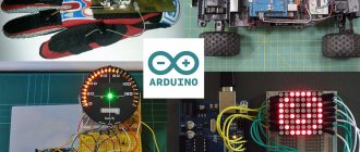
Independent production of various automatic systems has become available thanks to the use of ready-made Arduino boards. Programming such devices does not take much time and requires virtually no special knowledge. The Arduino light sensor is a fairly simple electrical system that can be installed and configured without any help.
This article will discuss the most popular options for using lighting elements of this type.
Sensor characteristics
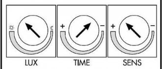
It is necessary to know in advance about the main parameters of this element so that during installation and operation the basic technical requirements for the safe use of devices of this type are not violated. The sensor board can be made using an analog or digital circuit. In the second case, the device is equipped with a trimming resistor, with which you can change the characteristics of the output signal manually.
Regardless of the type of device, the board is equipped with 3 contacts. Two connecting elements supply power (+5 and GND), the third contact is used to transmit a digital signal (indicated on the board as S or D0).
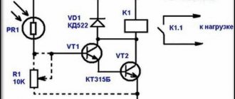
The light sensor of the Arduino hardware platform is a fairly simple circuit. The main element of such a device is a photoresistor, which changes the resistance of the electrical circuit depending on the illumination.
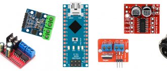
Infrared LED module KY-005 [4-5]
The module is an infrared LED without any additional elements; there is no additional resistance on the board.
The module has dimensions of 35 x 15 mm and a weight of 1.3 g. As the author understands, connecting this LED is no different from connecting a conventional visible LED. The central contact of the module is not connected to anything, the “-” contact is common, the “S” contact is informational. The author connected a 200 Ohm resistor in series with the LED, and the current consumed by the LED was 17 mA. The emission of this LED cannot be seen by the eye.
Using the camera's matrix, you can register the radiation of the LED; for this, it is advisable to set the sensitivity to at least 800 ISO, turn off the flash, open the camera aperture as much as possible and minimize ambient light.
Principle of operation
In an Arduino system, a sensor of this type will act as a voltage divider. On one arm of such a circuit, the potential difference will directly depend on the lighting level. On the other side, voltage is supplied to the analog input of the device.
The controller chip converts the received analog signal into a digital one. The output voltage coming from the device will be minimal (tends to zero) in normal lighting conditions and will increase significantly in the dark. The light control system is based on this principle.
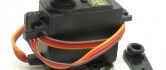
IR rangefinder module KY-032
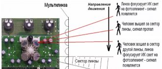
The module is designed to detect obstacles without direct contact with them. An IR LED and an IR photodetector are located on the module’s printed circuit board; when the intensity of radiation reflected from an obstacle exceeds a specified threshold, a sensor response signal is generated.
The module has dimensions of 45 x 16 x 12 mm, weight 4 g, and a mounting hole with a diameter of 3 mm is provided in the module's printed circuit board. The board has a four-pin connector through which the module is powered and information is transferred. The purpose of the connector pins is as follows: “GND” – common wire, “+” – +5V power supply, “OUT” – information output, “EN” – operating mode control. The “Pled” LED is used to indicate the power supply to the sensor; when triggered, the “Sled” LED lights up.
A low logic level appears at the information digital output “OUT” if there is an obstacle in the field of view of the sensor, otherwise a high logic level appears at the output. You can verify this by loading the AnalogInput2 program into the Arduino UNO memory, then when the sensor is triggered, the following picture will be observed in the serial port monitor of the Arduino IDE program.
According to sellers [21-22], the sensor can detect obstacles at a distance of 2 to 40 cm. The author of this review managed to achieve the sensor triggering at a distance of 5.5-3.5 cm from a white obstacle (sheet of paper). The sensor does not see a black rough surface (CD box) at all; the sensor registers a distance of about 2 cm on a black glossy surface.
According to the documentation, to adjust the modulation frequency of IR pulses to a frequency of 38 kHz, use a trimming resistor marked 103, and to adjust the sensitivity of the sensor, use a trimming resistor marked 507. As can be clearly seen in the previous photographs on the board that the author received, both variable resistors are marked 103. Perhaps This is a defect in this particular device. This may explain the short range of the sensor.
The sensor consumes a current of 4-5 mA in operating mode and 5-6 mA when triggered. If you set the sensor to the minimum sensing distance, you can slightly reduce the current consumption (by about 1 mA). In this photo, you can also see that when the sensor was triggered, the “Sled” LED lit up.
According to the description of this sensor, the “EN” pin is used to control the operating mode when the jumper is removed. When the logical level at the “EN” input is low, the sensor is turned on; when the logical level is high, the rangefinder module is in sleep mode with reduced power consumption.
However, according to the author’s observations, when the jumper was removed, when the “EN” output was not connected to anything, the current consumption increased to 13.5 mA, and the sensor stopped responding to the obstacle. With the jumper in place, applying a low logic level to “EN” (from the “GND” socket of the Arduino UNO board) led to a jump in current consumption to 150 mA. When “EN” is applied to a high logic level (from the 3.3 V socket of the Arduino UNO board) and the jumper is removed, the sensor works as usual. In general, in this mode the sensor behaved somewhat strangely, although this may have been due to errors in the experimental methodology that the author of this review made or due to the defective nature of this instance of the sensor.
Thus, on the one hand, the sensor can be used for its intended purpose, but in fact this sensor is not superior to simpler IR distance sensors [23]
Connection
The light sensor will work correctly in the Arduino system only if it is connected correctly. In order to do this work yourself, you need to prepare:
- Light sensor for the Arduino system.
- Arduino board (Nano, Uno, Mega).
- Any LED suitable for voltage.
- Solderless breadboard.
- Wires for connection.
When everything you need is prepared, you need to connect the 5v output of the Arduino board to the corresponding connector of the device. Then the ground (GND pin) is connected in the same way. The sensor output S is connected to pin2 of the main board.
If the element was connected correctly, then when the illumination changes, the electrical voltage at the S output will vary from 0 to 5 Volts. The digital sensor, in turn, will convert this indicator into a range of values from 0 to 1024, for further output to information display devices.
The LED is connected to pin 13 of the Arduino board, both when using analog and digital devices. If the device design has a trimming resistor, then it can be used to adjust the sensitivity of the working element within a wide range.
Program
Having connected the photoresistor according to a simple circuit, we begin to write a program. The first thing we will do is output the raw signal from the analog input to the serial port, in order to simply understand how the value at the A0 input changes. The corresponding program looks like:
const int pinPhoto = A0; int raw = 0; void setup() { Serial.begin(9600); pinMode( pinPhoto, INPUT ); } void loop() { raw = analogRead( pinPhoto ); Serial.println( raw ); delay(200); }
By running this program in our hackspace, we received the following values from the sensor:
Now let’s cover the sensor with our hand:
It can be seen that the value changes greatly. From 830 in case of direct light, up to 500 in case of shading (the appearance of an obstacle in the path of light). Knowing this behavior, we can numerically determine the triggering threshold. Let it be equal to, say, 600. Not exactly 500, because we want to protect ourselves from accidental activation. Suddenly a fly flies over the sensor - it will be slightly shaded and show 530.
Finally, let's add some action to the program that will be performed if the illumination level drops below a given threshold. The simplest thing we can do is to light the standard LED #13 on the Arduino. This results in a program like this:
const int pinPhoto = A0; const int led = 13; int raw = 0; void setup() { pinMode( pinPhoto, INPUT ); pinMode( led, OUTPUT ); } void loop() { raw = analogRead( pinPhoto ); if( raw < 600) digitalWrite( led, HIGH ); else digitalWrite( led, LOW ); delay(200); }
We cover the sensor with our hand (or turn off the light in the room) - the LED lights up. We remove our hand and it goes out. It works, however. Now imagine that you do not light an LED, but send a signal to a relay that turns on the lamp in the entrance of your house. The result is a ready-made device for saving energy. Or put such a sensor on the robot, and when night falls, it goes to bed with you