Automatic switches, also known as packets or automatic machines, are switching devices whose task is to supply current to the elements of the electrical network, and if its operation is disrupted, to automatically de-energize it. They are usually mounted in a distribution panel and allow you to protect the circuit from damage caused by excessive loads, voltage drops, and short circuits. In this material we will talk about how this equipment is classified, what are the features of its operation and how to correctly connect the machines in the electrical panel.
Classification of circuit breakers
Today, these devices are sold in a huge range. They differ from each other in the following characteristics:
- Main circuit current. It can be variable, constant or combined.
- Control method. The equipment can be operated manually or using a motor drive.
- Installation method. Devices can be plug-in, retractable or stationary.
- Type of release. These elements can be electronic, electromagnetic and thermal, as well as semiconductor.
- Body type. It can be modular, cast or open.
- Operating current indicator. Its value can range from 1.6 A to 6.3 kA.
Modern machines have a complex network protection mechanism. They have additional capabilities, which include:
- Possibility of opening an electrical circuit from a distance.
- Presence of signal contact groups.
- Automatic activation of the protective device in the event of a voltage drop to a critical value.
Step-by-step diagram for selecting a circuit breaker in the video:
Packers can have different standard sizes, and with their help you can protect electrical networks not only in apartments and private houses, but also at large facilities. These devices are produced both in Russia and abroad.
In domestic conditions, modular circuit breakers, small and lightweight, are most often used. They received the name “modular” due to their standard width, which is 1 module (1.75 cm).
In order to protect the electrical circuits of buildings, the following types of switches are installed:
- Differential.
- Automatic.
- RCD.
RCDs, as residual current devices are called for short, prevent electric shock to a person who touches the conductor, and prevent surrounding objects from igniting if there is an electricity leak, which can happen if the cable insulation is damaged.
Circuit breakers protect circuits from short circuits and allow you to turn the power on and off manually. The most advanced protective device is a differential circuit breaker. It combines the capabilities of a residual current device and a conventional circuit breaker. This package is equipped with built-in protection against too powerful electron flow. It is controlled by differential current.
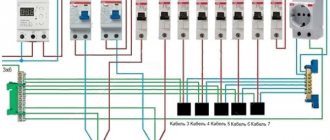
In single-phase electrical networks, single-pole and double-pole circuit breakers can be installed. The choice of package is influenced by the number of wires in the electrical wiring.
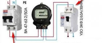
Typical single-phase network input circuit
The vast majority of apartments, garden plots and small household facilities such as garages are connected to a single-phase network. The method of connecting the measuring device (electricity meter) and the protective circuit elements (RCDs, circuit breakers and differential circuit breakers) is the same.
Depending on the operating conditions and powered devices, the connection diagram of a single-phase electric meter may undergo the following changes:
- No ground input.
- Lack of an individual input machine in front of the counter. It can be common to several circuits equipped with metering devices, or an ordinary manual switch (switch) can be installed instead.
- No branching into multiple circuits.
- Lack of RCDs and automatic circuit breakers protecting the line after the meter.
If there are no automatic circuit breakers or RCDs between the meter and consumers, then in the event of a short circuit or significant overload, the meter will break down. Therefore, protection is needed immediately after the metering device, especially since the simplest circuit breakers are cheap.
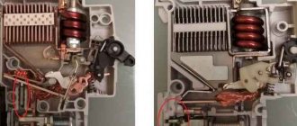
Circuit breakers: design and principle of operation
Before we consider the procedure for connecting circuit breakers in an electrical panel, let’s figure out how they are designed and on what principle they are triggered.
The product includes the following elements:
- Frame.
- Control system.
- Top and bottom terminals.
- Switching device.
- Arcing chamber.
Fire-resistant plastic is used as material for the manufacture of the housing and control system. The switching device contains moving contacts as well as fixed contacts.
An arc-extinguishing chamber is installed on a pair of contacts, which are the pole of the packetizer. When the contacts break under load, an electric arc occurs, which is extinguished by the camera. The latter consists of steel plates, insulated from each other and located at the same distance. The chamber plates help cool and extinguish the electric arc that appears during malfunctions. Machines can have one, two or four pairs of contacts.
Two-pole circuit breakers have two pairs of contacts: one is movable, the other is fixed.
Such a switch is equipped with a position indicator, which makes it easy to find out whether the machine is on (red light) or off (green).
The operating principle of circuit breakers is clearly shown in the video:
Security measures
Wiring the electrical panel must be done only by disconnecting it from the power supply. Installation is carried out according to the drawn up diagram; deviation from it, with a high degree of probability, will cause a short circuit.
It is imperative to observe the polarity of the wires; cable marking greatly simplifies this task:
- The black wire corresponds to the phase;
- blue – zero;
- yellow-green – grounding.
Without RCDs it is impossible to provide the required level of protection, so installing them is mandatory.
By adhering to the safety measures listed above and knowing how to connect the circuit breaker in the panel, you will be able to carry out any electrical wiring upgrade in your home.
Release
To turn off the machine in case of emergency situations, the device is equipped with a release. There are several types of these mechanisms, structurally different from each other and operating on different principles.
Thermal release
Structurally, this element includes a plate pressed from two different metals with an unequal coefficient of nonlinear expansion, which is connected to the circuit under load and is called bimetallic. When the release operates, the flow of electrons passing through the plate heats it.
Since the expansion coefficient of the metal is less than that of the plate, it bends towards it. When the current rating exceeds the permissible value, the curved plate, acting on the trigger, turns off the machine. If the ambient temperature deviates from the norm, the switch also trips.
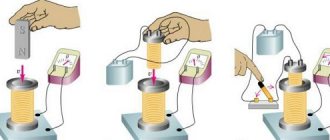
Magnetic release
This type of release is a coil consisting of an insulated copper winding and a core. Since load current flows through it, it must be connected to the circuit in series with the contacts. If the load current exceeds the permissible rating, the core will move under the influence of the magnetic field of the release and, through a disconnecting device, will open the contacts of the packet.
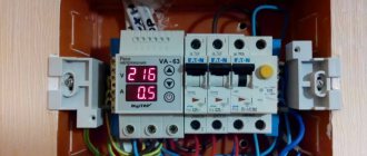
Selective circuit breakers with semiconductor releases
These devices are equipped with a special panel on which the machine's shutdown time is set. They provide a temporary delay in the event of a short circuit, which allows, in the event of an emergency, to turn off the emergency section without stopping the power supply to the facility.
A circuit breaker without a release is called a disconnector.
Division of responsibility for electrical appliances
The electrical distribution throughout the facility is protected by separate switches that regulate the maximum permissible current for sections of the circuit. Payment for their purchase and connection is made by the owner of the premises.
The electricity meter and the input machine can be physically located not only in the consumer’s area of responsibility. If these devices are located in a privatized apartment, in a garage, in a utility room or within the boundaries of a cottage or summer cottage, then their installation, maintenance and replacement are carried out by the owner of the property.
His responsibilities also include providing energy service employees and the management company with access to the meter for reading, sealing or checking. Also, specialists have the right to install magnetic seals. If the user of the premises refuses access to the premises without a valid reason, the electricity supplier may transfer him to a general tariff.
If the devices are located in municipal (non-privatized) property, common territory (entrances) or outside a private area, then all costs are borne either by the supplying organization or they are shared. In this case, the organization of work and payment is made by the management company, HOA, GSK or gardening partnership.
We talked in more detail about the legal intricacies of replacing and installing electricity meters in this material.
How to choose a machine?
Before you begin installing protective circuit breakers, you need to select them and also understand the intricacies of connection. People who want to know how to wire a circuit breaker ask various questions. For example, are the circuit breakers in the distribution board connected before or after the meter? Should an automatic input be installed? These and other connection nuances are of interest to users.
Basic parameters of circuit breakers
The characteristics of circuit breakers include:
- Rated current value (in Amperes).
- Operating voltage of the electrical network (in Volts).
- Maximum short circuit current.
- Ultimate switching capacity.
- Number of poles.
The maximum switching capacity is characterized by the maximum permissible value at which the switch is capable of operating. The PKS of household devices can be 4.5, 6 or 10 kA.
When choosing, they are most often guided by such basic indicators as short-circuit shutdown current, as well as overload current.
The cause of overload is the connection to the electrical network of devices with excessively high total power, which leads to exceeding the permissible temperature of contact connections and cables.
Taking this into account, it is necessary to install a packet in the circuit, the value of the shutdown current of which is not less than the calculated value, and better - if it slightly exceeds it. To determine the calculated current, you need to sum up the power of the devices that are supposed to be connected to the circuit (for each of them this indicator is available in the passport). The resulting number must be divided by 220 (the standard voltage value in a household network). The result obtained will be the value of the overload current. It should also be taken into account that it should not exceed the current rating that the wire can withstand.
The magnitude of the shutdown current during a short circuit is the indicator at which the circuit breaker is switched off. The short-circuit current is calculated when designing the line using formulas and reference tables, as well as using special equipment. Based on the obtained value, the type of protection is determined. At small sites and in household networks, type B or C machines are used.
We offer:
- Install circuit breakers, circuit breakers, RCDs, VDTs, RCBOs, contactors and automation in existing switchboards
- Repair of electrical panels, troubleshooting, technical audit, audit and condition check of existing panels and assemblies
- Turnkey assembly of electrical panels according to the existing design with high quality and full compliance with the single-line diagram
- Calculation of electrical loads and a single-line diagram for assembling a switchboard with justification for the ratings and types of protection devices
- Power supply project for a store, office, cottage, restaurant, canteen, cafe, production - “turnkey” with protection from technical supervision and expert examination
- As-built documentation for the existing electrical panel and single-line diagram “in fact”
- Preparation of the electrical panel for delivery to RosTechNadzor and removal of comments, protection during acceptance and inspection
Contact us, you will receive professional advice, assistance in resolving difficult and controversial issues, as well as electrical installation work of the highest quality.
{SOURCE}
Installing a circuit breaker in an electrical panel with your own hands
First of all, you need to decide on connecting the power wires, and only after that figure out how to connect the machine to the network. If you do not know whether the power conductors should be connected to the top or bottom of the package, please refer to the PUE requirements, which are the main guiding document for electrical installation work.
The Rules clearly state that the power cable must be connected to fixed contacts, and this requirement must be met in any circuit breaker connection diagram. In any modern device, the fixed contacts are located on top.
For installation you will need control devices and tools, which include:
- Assembly knife.
- Screwdrivers (phillips and slotted).
- Multimeter or indicator screwdriver.
So, how to connect the machine correctly? Let's consider the installation of circuit breakers in single-phase networks.
Two-phase and three-phase connections are more complex and it is advisable that they be carried out by a specialist.
Single-pole circuit breaker
The installation is carried out on a network where two cables are used for input: neutral (PEN) and phase (L). Such a system exists in old buildings. The supply conductor is connected to the input terminal of the machine, then from the output it passes through the meter, after which it is routed to the protective devices of specific groups. The supply neutral cable is also supplied to the PEN through an electric meter.
Application of one, two and three-pole circuit breakers on video:
Two-pole machine
We are considering the installation of a protective device in a single-phase network, where three conductors are used for input: phase, neutral and ground cable. The input terminals, designated on the device by numbers 1 and 3, are located at the top of the machine, and the output terminals (2 and 4) are at the bottom.
The power cable fits to input terminal 1 and is securely fixed to it. In a similar way, the neutral wire is attached to terminal 3. The phase passes through the electricity meter. Power is distributed evenly across groups of switches. From terminal 4, the neutral cable is connected to the N bus, passing through the meter and the RCD.
Connecting wires
Any circuit breaker is accompanied by a passport that states how to correctly connect the wires to its terminals. The document contains all the necessary information - from the cross-section of the cables and the type of their connection to the length of the stripped part of the conductor.
Stripping the ends of the wires for connecting household machines is done with a mounting knife about 1 cm. You can distinguish the conductors by their color markings:
- Phase cable – white or brown.
- Neutral wire – black, blue or light blue.
- The grounding conductor is green.
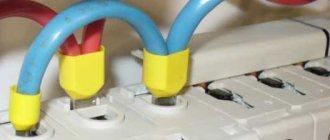
After stripping the end of the wire with a knife, it must be inserted into the contact clamp and secured with a fixing screw. The screws are tightened with a screwdriver. After fastening, the wire needs to be tugged a little to make sure it is securely fastened. If a flexible wire is used to connect to the package, then to increase the reliability of the connection, special tips should be used.
To ensure that the installation of machines in the electrical panel and the connection of cables to them are carried out correctly, you need to remember common mistakes and avoid them during operation:
- The insulating layer gets under the contact clamp.
- Too much force when tightening, which can lead to deformation of the body and, as a result, to breakage of the machine.
Often several protective devices are installed in a distribution board. To connect them, inexperienced specialists use jumpers.
In principle, this is not a mistake, but still in this case it is better to use a special tire cut to the required size - the so-called comb. With its help, the wires are connected to the packets in the required sequence.
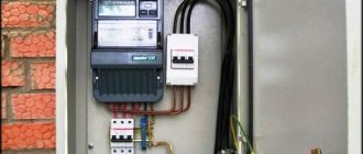
Main process
So, in the initial position we have an electrical panel in which the products will be installed, as well as all the wires (input and outgoing to consumers).
Let's look at the instructions for dummies using the example of connecting a two-pole circuit breaker in a panel:
- The first step is to turn off the power and check its presence using a multimeter or an indicator screwdriver. we provided to the readers!
- The machine is installed on a special mounting DIN rail and snapped into place with a latch. You can do without a DIN rail, but it is less convenient.
- The conductors of water and outgoing conductors are stripped to 8-10 mm.
- You need to connect the input zero and phase to the two upper terminals (do not forget about the recommendations indicated above).
- Accordingly, the outgoing zero and phase (those that go to electrical appliances, sockets and switches) are fixed in the two lower holes.
- After this, the place must be checked manually for reliability. To do this, you need to carefully take the conductor and move it in different directions. If the core remains in place, then the connection is reliable, otherwise be sure to tighten the screw again.
- After all electrical installations, the robot is supplied with voltage to the network and the functionality of the product is checked.
That's all the instructions for connecting a circuit breaker in a single-phase circuit. As you can see, there is nothing complicated, you just need to be careful. We also recommend watching the video tutorial, which discusses the connection process in more detail:
Visual video instructions
Installation of a low-quality single-pole circuit breaker
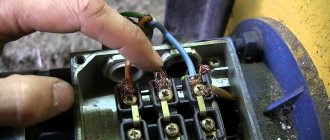
Features of connecting SIP to the input circuit breaker
Self-supporting insulated wire is widely used to transmit electricity to the home network from overhead power lines instead of conventional cable. Despite all the advantages of this conductor, connecting the SIP to the circuit breaker should not be done directly, since during operation the aluminum begins to “float” and the insulation burns. Ultimately, this leads, at best, to failure of the machine, and at worst, to a fire. The easiest way to avoid such trouble is to connect the SIP to the machine through a special adapter sleeve.
This device ensures the transition from aluminum wire to copper. You can buy it in a specialized store.
Step-by-step installation of the machine is shown in the following video: