So, the most important block of any transmitter is the generator. How stable and accurate the generator operates determines whether someone can pick up the transmitted signal and receive it normally. There are simply a lot of different bug circuits lying around on the Internet, which use various generators. Now we categorize all this a little.
The ratings of the parts of all the given circuits are calculated taking into account the fact that the operating frequency of the circuit is 60...110 MHz (that is, it covers our favorite VHF band).
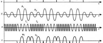
Generation mechanism
A simplified diagram can be represented as follows:
Instead of a transistor, we put a certain “element with negative resistance”. In essence, it is a reinforcing element. That is, the current at its output is greater than the current at the input (so that’s tricky).
An oscillatory circuit is connected to the input of this element. Feedback is supplied from the output of the element to the same oscillatory circuit (via capacitor C2). Thus, when the current at the input of the element increases (the loop capacitor is recharged), the current at the output also increases. Through feedback, it is fed back to the oscillatory circuit - “feeding” occurs. As a result, undamped oscillations settle down in the circuit.
Everything turned out to be simpler than steamed turnips (as always).
Operation of the device
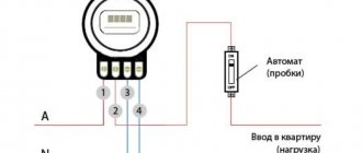
If you look in more detail at the operation of a high-frequency generator, then the equipment stops due to the fact that a capacitor is used in the device circuit. The connection is made precisely to this part, which has a charge that completely coincides with the sinusoid of the voltage flowing in the network. The charge is carried out through pulses with high frequency. Thus, it turns out that the current that the consumer consumes from his home network becomes a high-frequency pulse. Conventional electronic meters installed in homes are characterized by a lack of sensitivity to such fluctuations. This means that the unit will take into account the pulse current consumption with a negative error.
Varieties
On the vast Internet you can also find the following implementation of the same generator:
The circuit is called "capacitive three-point". The operating principle is the same.
In all these schemes, the generated signal can be removed either directly from the collector VT 1, or use a coupling coil connected to a loop coil for this purpose.
Tube RF
One of the types of high-frequency signal generators is tube devices. Such devices are used to obtain plasma with the required parameters. To do this, you need to apply a certain discharge to the power of the device. The key elements of such devices are emitters, the operation of which is based on the principle of power supply.
Power amplifiers are another important element for tube HF operation. These parts, installed on lamps, are used to convert direct current into alternating current. Naturally, the operation of a lamp generator is impossible without the lamp itself. You can use various elements. The GU-92A tetrode has become quite common. This part is an electron tube, the operation of which uses four elements: anode, cathode, shielding and control grids.
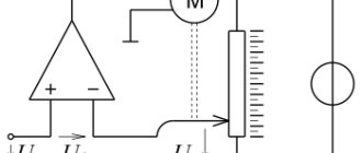
Inductive three-point
I choose this scheme and recommend it to you.
R1 – limits the generator current R2 – sets the base bias C1, L1 – oscillatory circuit C2 – PIC capacitor
Coil L1 has a tap to which the emitter of the transistor is connected. This tap should not be located exactly in the middle, but closer to the “cold” end of the coil (that is, the one that is connected to the power wire). In addition, you can not make a tap at all, but wind an additional coil, that is, make a transformer:
These schemes are identical.
Generation mechanism:
To understand how such a generator works, let's look at the second circuit. In this case, the left (according to the diagram) winding will be the secondary, the right - the primary.
When the voltage on the upper plate of C1 increases (that is, the current in the secondary winding flows “up”), an opening pulse is applied to the base of the transistor through the feedback capacitor C2. This causes the transistor to apply current to the primary winding, this current causes the current in the secondary winding to increase. There is a replenishment of energy. In general, everything is also quite simple.
Features of HF performance
The generator is executed entirely on logical elements. It produces oscillations or pulses with a frequency of 2 kHz and an amplitude of 5 Volts. There is also such a characteristic as the signal frequency. The value of this parameter is determined by elements C2 and R7. Standard notation schemes use this signature format. The properties that these elements provide can be used to adjust the maximum error in metering energy consumption. Elements such as T2 and T3 - transistors - are responsible for creating pulses. Together they are called the impulse creator. This part is also responsible for the correct operation of transistor T1.
Devices such as rectifier, transformer and others are used as a small power supply. The main task is to supply energy for the operation of the microcircuit with other elements. These small power supplies are usually rated at 36V.
Push-pull generator for the lazy
The simplest generator circuit I've ever seen:
In this circuit one can easily see the similarity with a multivibrator. I'll tell you more - this is a multivibrator. Only instead of delay circuits on a capacitor and resistor (RC circuit), inductors are used here. Resistor R1 sets the current through the transistors. In addition, without it, generation simply will not work.
Generation mechanism:
Let's say VT1 opens, collector current VT1 flows through L1. Accordingly, VT2 is closed, and the opening base current VT1 flows through L2. But since the resistance of the coils is 100...1000 times less than the resistance of resistor R1, then by the time the transistor is fully opened, the voltage across them drops to a very small value, and the transistor closes. But! Since before closing the transistor, a large collector current flowed through L1, at the moment of closing there is a voltage surge (self-induction emf), which is supplied to the base of VT2 and opens it. Everything starts over again, only with a different generator arm. And so on…
This generator has only one advantage - ease of manufacture. The rest are cons.
Since it does not have a clear timing link (oscillating circuit or RC circuit), it is very difficult to calculate the frequency of such a generator. It will depend on the properties of the transistors used, the supply voltage, temperature, etc. In general, it is better not to use this generator for serious things. However, in the microwave range it is used quite often.
A simple generator for tuning radio receiving equipment (100 kHz - 150 MHz)
Usually, when setting up radio receiving equipment, an HF generator is used, and a LF generator is used for modulation.
Both are sinusoidal generators made using fairly complex circuits. However, in many cases, a simple probe generator generating square-wave pulses in the range from 100 kHz to 150 MHz, and a low-frequency pulse generator in the range 300-2000 Hz, may be sufficient.
Of course, rectangular pulses have a serious drawback - a large number of harmonics. But this can also be an advantage, since the signal from such a generator can also be heard on the HF radio bands. And if necessary, you can use a circuit to isolate high-frequency harmonics.
Push-pull generator for hard workers
The other generator that we will consider is also a push-pull generator. However, it contains an oscillatory circuit, which makes its parameters more stable and predictable. Although, in essence, it is also quite simple.
Here he is
What do we see here?
We see the oscillatory circuit L1 C1, And then we see a pair for each creature: Two transistors: VT1, VT2 Two feedback capacitors: C2, C3 Two bias resistors: R1, R2
An experienced eye (and not a very experienced one) will find in this circuit similarities with a multivibrator. Well, that’s how it is!
What is special about this scheme? Yes, because due to the use of push-pull switching, it allows you to develop double power, compared to circuits of 1-cycle generators, at the same supply voltage and provided that the same transistors are used. Wow! Well, in general, she has almost no flaws