General characteristics and classification of indicator devices
Indicator devices or display elements form the basis of information display devices, which are designed to convert an electrical signal into a visible form.
Incandescent indicators are devices that use the glow of an incandescent filament heated by an electric current. They are miniature incandescent lamps that illuminate the colored housings (light filters) of indicators and buttons or certain images, signs, and symbols.
Electroluminescent indicators are devices that use the glow of certain substances under the influence of an electric field. For example, vacuum-luminescent indicators. They are multi-anode lamps that have a cathode that emits electrons and a grid that controls the indicator current. Anodes are made in the form of sign-synthesizing segments coated with phosphor. When electrons collide with the surface of the anodes, they cause the phosphor to glow in the required color. Each anode is separately supplied with supply voltage. These indicators allow you to obtain a large number of elements and characters of different colors and high brightness.
The operation of electron beam devices is based on the glow of a phosphor when bombarded with electrons.
Gas-discharge (ion) devices use the glow of gas during an electrical discharge. They consist of a sealed cylinder with electrodes sealed into it (in the simplest case, an anode and cathode - a neon lamp), and filled with inert gases (neon, helium, argon, krypton) under low pressure. When voltage is applied, the gas glows. The color of the glow is determined by the composition of the filler gas. Used to indicate direct or alternating voltage. Today, gas-discharge devices are used for the manufacture of plasma panels.
A plasma panel is a matrix of cells sandwiched between two glasses. Each cell is coated with a phosphor (adjacent cells form triads of three colors - red, green and blue R, G, B) and filled with an inert gas - neon or xenon. When electric current is applied to the electrodes of the cell, the gas transforms into a plasma state and causes the phosphor to glow. The main advantage of plasma panels is their large screen sizes. Plasma panels have high contrast (the difference between black and white), a wide viewing angle and a wide operating temperature range. Along with the advantages, there are also disadvantages: only large panels, gradual “burnout” of the phosphor, relatively high power consumption.
Semiconductor indicators are devices whose operating principle is based on the emission of light quanta in the region of the pn junction to which voltage is applied.
— discrete (point) semiconductor indicators – LEDs;
— character indicators — for displaying numbers and letters;
LEDs, or light-emitting diodes, have become widespread due to their compactness, the ability to produce any color of radiation, the absence of a fragile glass bulb, low supply voltages and ease of switching on.
An LED consists of one or more crystals that emit radiation and are located in the same housing with a lens and a reflector, which forms a directed light beam in the visible or infrared (invisible) part of the spectrum.
LED matrices (modules) are a certain number of LEDs, made in the form of a complete block and having a control circuit. Matrices are used to make LED screens.
Liquid crystal indicators (LCDs) - their operation is based on changes in the optical properties of liquid crystals under the influence of an electric field.
Liquid crystals are organic liquids with an ordered arrangement of molecules characteristic of crystals. Liquid crystals are transparent to light rays, but under the influence of an electric field their structure is disrupted, the molecules are arranged randomly, and the liquid becomes opaque.
Oscilloscopes
An electronic oscilloscope is a device that allows you to visually observe and photograph the form and nature of rapidly changing processes occurring in any electrical circuit.
The cathode ray tube is one of the main parts of the device (Fig. 2.3.1.). It is a glass container, similar to a flask with a flat bottom, coated on the inside with a substance that glows when struck by electrons (phosphor). Inside the tube cylinder there are electrodes: filament H, cathode K, control electrode-modulator M, anodes A1 and A2 and deflecting plates Y-Y', X-X'. A set of electrodes, excluding deflection plates, designed to create an electron beam is called an electron spotlight.
The filament is powered by low voltage alternating current and heats the cathode, made in the form of a cylinder, surrounding the filament. The end part of the cathode K is covered with an oxide layer that emits electrons. Around the cathode there is a cylindrical electrode with a hole in the end, called modulator M. A negative potential is applied to it relative to the cathode, due to which the flow of electrons emitted by the cathode is grouped in the form of a beam passing through the hole in the modulator. The brightness of the electron beam is also adjusted using the modulator.
In order for the electron flow to reach the screen and concentrate on it in the form of a sharp point, a system of anodes A1 and A2 is used, creating an accelerating electric field that acts on the electron flow and focuses the electron beam. A positive voltage of 200 to 1000 V is applied to the first anode A1, depending on the type of tube, and to the second anode A2 - from 1000 to 4000 V. Due to the potential difference of the anodes, an electric field is formed between them. An electron beam, entering this field, is deflected by it in the direction of the horizontal axis and receives acceleration in the direction of the screen E. Consequently, the anodes act as a collecting lens, directing the electron beam to the screen in the form of a sharply defined point.
DIGITAL INSTRUMENTS - INDICATORS
Visibility is a big deal. So popular wisdom says: “It’s better to see once than to hear a hundred times.” And in electronics, where the ongoing processes in the operation of a particular device are often confirmed indirectly, or even generally implied and even taken on faith, it is generally difficult to overestimate the visual display. It is not for nothing that oscilloscopes are so revered among radio amateurs, giving them the opportunity to “look” even into the process. But I won’t talk about the complex – I’d like to deal with the simple ones. I have assembled almost a dozen different chargers, and to charge batteries I increasingly use a simple laboratory power supply that has a visual display of the output voltage and current. The measuring heads clearly inform how many volts and milliamps go to the battery being charged. But it’s not possible to use them everywhere; even the smallest of them will often still be prohibitively large for many amateur radio homemade products. But dial indicators from tape recorders and other radio devices of the last century, which have not been sold out in the bazaars to this day, will be just right here. Here are some of them:The M476 dial indicator is designed to operate in DC circuits at any scale position. Total deflection current (depending on model) 40 - 300 µA. Internal resistance 4000 Ohm. Scale length - 28 mm, weight 25 g.
The M4762 dial indicator is designed to operate with a vertical scale position. Deviation current 220 - 270 µA. Internal resistance 2800 Ohm. Dimensions 49 x 45 x 32 mm. Scale length – 34 mm.
The M68502 dial indicator is designed to work at any scale position. The total deviation current is no more than 250 µA. Internal resistance 1000 Ohm. Dimensions 21.5 x 60 x 60.5 mm. Weight 30 gr. These indicators and others like them are united by:
- small size
- simplicity of design
- low cost
- and, of course, the principle of operation
The operating principle is based on the interaction of two magnetic fields. The fields of a permanent magnet and the field formed by a current passing through a frameless frame, which consists of a large number (115 - 150) turns of copper wire with a diameter of only 8 - 9 microns. Without delving into the nuances, we can name two main actions that need to be performed in order to make it possible to use the existing indicator:
- Equip it with a shunt or additional resistance (used to change the upper limit of measurement), depending on how you will use it (voltmeter / ammeter).
- Make a new scale.
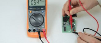
Selection of a shunt - we place a low-resistance resistor suitable for the power on the contacts of the indicator, parallel to it a variable resistor with high resistance, set the current for which the indicator will be used, and by rotating the variable resistor set the arrow to the rightmost division of the scale.
Selection of additional resistance - place a high-resistance variable resistor suitable for power on one of the indicator contacts, set the voltage and by rotating the resistor set the arrow to the rightmost division of the scale. Now it's a small matter - you need to “get” to the scale inside the indicator, and for this you need to open its case. And here it’s time to get confused, because there are no fasteners and the body, consisting of two halves, is simply glued together. Therefore, how well this operation is performed and what kind of glue is used, you can judge whether you were born under a lucky star)). We will open the M4762 indicator, in my opinion, the most difficult option. But even if dichloroethane was used, you should not despair, since it probably dissolved only the top layer of organic glass - the material from which the case is made. Therefore, we take a file with a large notch in our hands and grind around the perimeter of the junction of the two halves of the body, evenly on all sides.
During the grinding process, it is periodically necessary to try to separate the halves of the body, while applying some force. As a result, everything worked out.
Making a new scale is not difficult:
- scan the old one
- insert the image into the specialized graphic editor Sprint-Layout
- outline
- print it out
- cut and glue in place
Whatever you say, even the simplest probe with an indicator is already a whole measuring device!
Indicators Forum
Forum for discussing the material DIGITAL INSTRUMENTS - INDICATORS
MEMS
MICROPHONES MEMS microphones are a new quality in sound recording. Detailed description of the technology.
About the use of wireless power technology for various devices.
Provides basic information about planar fuses, including their technical characteristics and applications.ELECTROLYSER FOR HYDROGEN PRODUCTION
Review of a Chinese device for water electrolysis - photos, videos, description of work.
Dial indicator: description, device characteristics
A dial indicator is a device designed for relative measurements of deviations in shape, external dimensions, and surface location. It represents a system of connecting gears and levers that enhance the movement of the rod and convert these movements into instrument readings. In most watch-type devices, moving the measuring rod of the device by one millimeter corresponds to one revolution of the hand. In this case, the division price, and therefore the value of the movement of the rod, which the device can reliably measure, is 0.01 mm. The measurement limits are 0-5 mm and 0-10 mm. Dial indicators come in three accuracy classes: zero, first, and second. Devices of the zero type allow the smallest measurement error, and those of the second class allow the greatest error.
For the purpose of relative measurements in the field of metalwork and tool production in labor-intensive places and in the manufacture of various parts, a lever-gear indicator of especially small overall dimensions is used.
A dial indicator is also used to measure the runout value of cylindrical parts or to check the parallel sides of a product, for example, prisms. In order to determine the runout value, the part must be installed on the centers of a special device.
All clock indicator instruments are unified. They produce splash-proof models of devices based on three stones, with unloading in the event of an impact on the rod, with a measurement range of 0-25 mm and 0-50 mm.
The dial indicator is capable of measuring the depth of drilled holes. Such devices, like micrometers, have a measurement accuracy of 0.01 mm. The small arrow of the device indicates millimeters, and the large arrow indicates hundredths of a millimeter. To measure the internal diameter, use a special device placed on the indicator.
The hour indicator is used to determine deviations in the dimensions or position of the part being tested. Due to the fact that the dial is divided into 100 parts, the reading is carried out with an accuracy of 0.005 mm. The dial of the device has a two-sided graduation from zero: divisions to the right indicate the deviation of dimensions in the direction of increase, respectively, to the left - in the direction of decrease.
To measure linear quantities, deviations of geometric shape, as well as the relative placement of surfaces of parts, a dial indicator with additional devices is used. Such measurements are carried out using the absolute measurement method, when the measured value does not exceed the measurement limit of the instrument scale, and the relative measurement method, by comparison with the gauge length.
There are indicators based on the use of gears. In such devices, the spring-loaded measuring rod and the gear rack are structurally made as a single unit. The rack meshes with a 16-tooth wheel.
In conclusion, we note that dial indicators are the most common and widely used measuring devices in the designs and elements of control devices. These devices with a division value of 0.01 mm are used extremely rarely - firstly, because the control of parts and workpieces does not require such high accuracy, and, secondly, due to the rapid wear of measuring devices when working in forging conditions. stamping and foundry shops.