When designing electrical wiring, it is necessary to make accurate calculations of the voltage loss in the cable. This prevents the surface of the wires from becoming too hot during operation. Thanks to these measures, it is possible to avoid short circuits and premature breakdown of household appliances.
In addition, the formula allows you to correctly select the diameter of the wire cross-section, which is suitable for different types of electrical installation work. A wrong choice can cause a breakdown of the entire system. Online calculation helps to make the task easier.
Voltage drop on the wire
The article will be specific, with theoretical calculations and formulas. For those who are not interested in what comes from and why, I advise you to go straight to Table 2 - Selecting the wire cross-section depending on the current and voltage drop.
And also - calculation of voltage losses on a long powerful three-phase cable line. An example of calculating a real line.
So, if we take the power constant, then as the voltage decreases, the current should increase, according to the formula:
P = I U. (1)
In this case, the voltage drop on the wire (losses in the wires) due to resistance is calculated based on Ohm’s law:
U = R I. (2)
From these two formulas it is clear that as the supply voltage decreases, the losses on the wire increase. Therefore, the lower the supply voltage, the larger the cross-section of the wire must be used to transmit the same power.
For direct current, where low voltage is used, you have to carefully approach the issue of cross-section and length, since these two parameters determine how many volts will be wasted.
Ways to reduce losses in electrical networks
A network user cannot influence losses in power lines, but can reduce the voltage drop on a section of the circuit by correctly connecting its elements.
It is better to connect a copper cable to a copper cable, and an aluminum cable to an aluminum one. It is better to minimize the number of wire connections where the core material changes, since in such places not only energy is dissipated, but also heat generation increases, which can be a fire hazard if the level of thermal insulation is insufficient. Considering the conductivity and resistivity of copper and aluminum, it is more energy efficient to use copper.
If possible, when planning an electrical circuit, it is better to connect any inductive elements such as coils (L), transformers and electric motors in parallel, since according to the laws of physics, the total inductance of such a circuit decreases, and when connected in series, on the contrary, it increases.
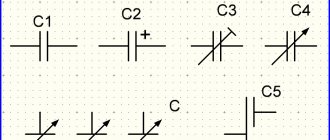
To smooth out the reactive component, capacitor units (or RC filters in combination with resistors) are used.
Depending on the principle of connecting capacitors and the consumer, there are several types of compensation: personal, group and general.
- With personal compensation, the capacitors are connected directly to the place where the reactive power appears, that is, its own capacitor - to the asynchronous motor, another one - to the gas-discharge lamp, another one - to the welding one, another one - for the transformer, etc. At this point, the incoming cables are relieved of reactive currents to the individual user.
- Group compensation involves connecting one or more capacitors to several elements with large inductive characteristics. In this situation, the regular simultaneous activity of several consumers is associated with the transfer of total reactive energy between loads and capacitors. The line that supplies electrical energy to a group of loads will be unloaded.
- General compensation involves inserting capacitors with a regulator in the main panel, or main switchboard. It makes an assessment based on the current consumption of reactive power and quickly connects and disconnects the required number of capacitors. As a result, the total power taken from the network is reduced to a minimum in accordance with the instantaneous value of the required reactive power.
- All reactive power compensation installations include a pair of capacitor branches, a pair of stages, which are formed specifically for the electrical network, depending on the potential loads. Typical step dimensions: 5; 10; 20; thirty; 50; 7.5; 12.5; 25 sq.
To acquire large steps (100 or more kvar), small ones are connected in parallel. Network loads are reduced, switching currents and their interference are reduced. In networks with many high harmonics of the mains voltage, capacitors are protected by chokes.
Automatic compensators provide the network equipped with them with the following advantages:
- reduce the load on transformers;
- simplify the requirements for cable cross-sections;
- make it possible to load the power grid more than is possible without compensation;
- eliminate the causes of a decrease in network voltage, even when the load is connected by long cables;
- increase the efficiency of mobile fuel generators;
- simplify starting electric motors;
- increase cosine phi;
- eliminate reactive power from circuits;
- protect against overvoltage;
- improve the regulation of network characteristics.
DC resistance of copper wire
The wire resistance depends on the resistivity ρ, which is measured in Ohm mm²/m. The resistivity value determines the resistance of a piece of wire 1 m long and 1 mm² cross-section.
The resistance of the same piece of copper wire 1 m long is calculated by the formula:
R = (ρ l) / S, where (3)
R – wire resistance, Ohm,
ρ – wire resistivity, Ohm mm²/m,
l – wire length, m,
S – cross-sectional area, mm² .
The resistance of the copper wire is 0.0175 Ohm mm²/m; we will use this value in further calculations.
It is not a fact that copper cable manufacturers use pure copper “0.0175 standard”, so in practice the cross-section is always taken with a margin, and against wire overload they use protective circuit breakers, also with a margin.
From formula (3) it follows that for a piece of copper wire with a cross-section of 1 mm² and a length of 1 m, the resistance will be 0.0175 Ohm. For a length of 1 km – 17.5 Ohms. But this is only a theory, in practice everything is worse.
Below I will give a plate calculated using formula (3), which shows the resistance of a copper wire for different cross-sectional areas.
Table 0. Resistance of copper wire depending on cross-sectional area
| S, mm² | 0,5 | 0,75 | 1 | 1,5 | 2,5 | 4 | 6 | 10 |
| R for 1m | 0,035 | 0,023333 | 0,0175 | 0,011667 | 0,007 | 0,004375 | 0,002917 | 0,00175 |
| R for 100m | 3,5 | 2,333333 | 1,75 | 1,166667 | 0,7 | 0,4375 | 0,291667 | 0,175 |
Potential
The electric field strength characterizes its power properties. To quantitatively characterize the energy capabilities of the field, the concept of potential was introduced. The electrostatic field potential φ is the ratio of the potential energy Wp of the charge in the field to the charge value q:
$ φ = {Wp\over {q * U}} $ (3).
Then the voltage between two points of the electrical circuit (1st and 2nd) can be expressed as follows:
$ U = φ_1 – φ_2 $ (4).
That is, the physical meaning of the voltage value becomes more clear - this is the potential difference at the starting point 1 and ending point 2.
To understand the semantic meaning of voltage, you can use the analogy with the gravitational field, which is also potential. The mass of a body m is similar to the magnitude of the charge q, and the height h from which, for example, a stone or a stream of water rotating a turbine can fall is similar to the voltage U. Let us recall the expression for the potential energy of a body of mass m in the Earth’s gravitational field:
$E_p = m * g * h $ (5),
where: g is the acceleration of gravity, 9.8 m/s2. It can be seen that formulas (2) and (4), obtained for different potential fields, are very similar.
Calculation of voltage drop on a wire for direct current
Now, using formula (2), we calculate the voltage drop on the wire:
U = ((ρ l) / S) I, (4)
That is, this is the voltage that will drop on a wire of a given cross-section and length at a certain current.
These are the tabular data for a length of 1 m and a current of 1A:
Table 1. Voltage drop on a 1 m copper wire of different cross-sections and a current of 1A:
| S, mm² | 0,5 | 0,75 | 1 | 1,5 | 2,5 | 4 | 6 | 8 | 10 |
| U, B | 0,0350 | 0,0233 | 0,0175 | 0,0117 | 0,0070 | 0,0044 | 0,0029 | 0,0022 | 0,0018 |
This table is not very informative; it is more convenient to know the voltage drop for different currents and cross sections. Let me remind you that calculations for choosing the wire cross-section for direct current are carried out according to formula (4).
Table 2. Voltage drop for different wire cross-sections (top row) and current (left column). Length = 1 meter
| S,mm² I,A | 1 | 1,5 | 2,5 | 4 | 6 | 10 | 16 | 25 |
| 1 | 0,0175 | 0,0117 | 0,0070 | 0,0044 | 0,0029 | 0,0018 | 0,0011 | 0,0007 |
| 2 | 0,0350 | 0,0233 | 0,0140 | 0,0088 | 0,0058 | 0,0035 | 0,0022 | 0,0014 |
| 3 | 0,0525 | 0,0350 | 0,0210 | 0,0131 | 0,0088 | 0,0053 | 0,0033 | 0,0021 |
| 4 | 0,0700 | 0,0467 | 0,0280 | 0,0175 | 0,0117 | 0,0070 | 0,0044 | 0,0028 |
| 5 | 0,0875 | 0,0583 | 0,0350 | 0,0219 | 0,0146 | 0,0088 | 0,0055 | 0,0035 |
| 6 | 0,1050 | 0,0700 | 0,0420 | 0,0263 | 0,0175 | 0,0105 | 0,0066 | 0,0042 |
| 7 | 0,1225 | 0,0817 | 0,0490 | 0,0306 | 0,0204 | 0,0123 | 0,0077 | 0,0049 |
| 8 | 0,1400 | 0,0933 | 0,0560 | 0,0350 | 0,0233 | 0,0140 | 0,0088 | 0,0056 |
| 9 | 0,1575 | 0,1050 | 0,0630 | 0,0394 | 0,0263 | 0,0158 | 0,0098 | 0,0063 |
| 10 | 0,1750 | 0,1167 | 0,0700 | 0,0438 | 0,0292 | 0,0175 | 0,0109 | 0,0070 |
| 15 | 0,2625 | 0,1750 | 0,1050 | 0,0656 | 0,0438 | 0,0263 | 0,0164 | 0,0105 |
| 20 | 0,3500 | 0,2333 | 0,1400 | 0,0875 | 0,0583 | 0,0350 | 0,0219 | 0,0140 |
| 25 | 0,4375 | 0,2917 | 0,1750 | 0,1094 | 0,0729 | 0,0438 | 0,0273 | 0,0175 |
| 30 | 0,5250 | 0,3500 | 0,2100 | 0,1313 | 0,0875 | 0,0525 | 0,0328 | 0,0210 |
| 35 | 0,6125 | 0,4083 | 0,2450 | 0,1531 | 0,1021 | 0,0613 | 0,0383 | 0,0245 |
| 50 | 0,8750 | 0,5833 | 0,3500 | 0,2188 | 0,1458 | 0,0875 | 0,0547 | 0,0350 |
| 100 | 1,7500 | 1,1667 | 0,7000 | 0,4375 | 0,2917 | 0,1750 | 0,1094 | 0,0700 |
What explanations can be made for this table?
1. in red those cases when the wire will overheat, that is, the current will be higher than the maximum permissible for a given cross-section. I used the table given on SamElektrika: Selecting the cross-sectional area of the wire.
2. Blue color - when the use of too thick wire is economically and technically impractical and expensive. The threshold was taken to be a drop of less than 1 V over a length of 100 m.
How to use the section selection table?
Table 2 is very easy to use. For example, you need to power a certain device with a current of 10A and a constant voltage of 12V. The line length is 5 m. At the output of the power supply we can set the voltage to 12.5 V, therefore, the maximum drop is 0.5 V.
Available - wire with a cross-section of 1.5 square. What do we see from the table? At 5 meters with a current of 10 A we will lose 0.1167 V x 5m = 0.58 V. It seems to be suitable, considering that most consumers tolerate a deviation of +-10%.
But. After all, we actually have two wires, plus and minus, these two wires form a cable on which the load supply voltage drops. And since the total length is 10 meters, the drop will actually be 0.58 + 0.58 = 1.16 V.
In other words, in this situation, the output of the power supply unit is 12.5 Volts, and the input of the device is 11.34. This example is relevant for powering an LED strip.
And this is without taking into account the contact resistance of the contacts and the imperfection of the wire (“sample” of copper is not the same, impurities, etc.)
Therefore, such a piece of cable most likely will not work; you need a wire with a cross-section of 2.5 square. It will give a drop of 0.7V on a 10m line, which is acceptable.
What if there is no other wire? There are two ways to reduce voltage loss in wires.
1. The 12.5 V power supply should be placed as close to the load as possible. If we take the example above, 5 meters will suit us. This is what they always do to save on wires.
2. Increase the output voltage of the power supply. The risk is that as the load current decreases, the voltage across the load may rise to unacceptable limits.
For example, in the private sector, 250-260 Volts are installed at the output of the transformer (substation); in houses near the substation, the light bulbs burn like candles. I mean, not for long. And residents on the outskirts of the area complain that the voltage is unstable and drops to 150-160 Volts. Loss of 100 Volts! Multiplied by the current, you can calculate the power that heats the street, and who pays for it? We, the “losses” column on the receipt.
Parallel connection of conductors
A parallel connection of conductors looks like this.
parallel connection of resistors
Well, I think let's start with resistance.
Resistance when connecting conductors in parallel
Let's label the terminals as A and B
In this case, the total resistance RAB will be found according to the formula
If we have only two parallel connected conductors
Then in this case you can simplify the long, inconvenient formula and it will take the following form.
Voltage when connecting conductors in parallel
Here, I think there is no need to guess anything. Since all conductors are connected in parallel, the voltage will be the same for all.
It turns out that the voltage on R1 will be the same as on R2, as on R3, and on Rn
Conclusion on choosing the wire cross-section for constant voltage:
The shorter and thicker the wire through which direct current flows, the lower the voltage drop across it, the better . That is, the voltage loss in the wires is minimal.
If you look at Table 2, you need to select the values from the top-right, without going into the “blue” zone.
For alternating current the situation is the same, but the issue is not so acute - there power is transferred by increasing the voltage and decreasing the current. See formula (1).
In conclusion, here is a table in which the DC voltage drop is set to a limit of 2%, and the supply voltage is 12 V. The required parameter is the maximum wire length.
Attention! This refers to a two-wire line, for example a cable containing 2 wires. That is, the case when, through a cable 1 m long, the current makes a path of 2 m, back and forth. I brought this option because... it is most often encountered in practice. For one wire, to find out the voltage drop across it, you need to multiply the number inside the table by 2. Thanks to attentive readers!
Table 3. Maximum wire length for 2% DC voltage drop.
| S,mm² I,A | 1 | 1,5 | 2,5 | 4 | 6 | 10 | 16 | 25 | 35 | 50 | 75 | 100 |
| 1 | 7 | 10,91 | 17,65 | 28,57 | 42,86 | 70,6 | 109,1 | 176,5 | 244,9 | – | – | – |
| 2 | 3,53 | 5,45 | 8,82 | 14,29 | 21,4 | 35,3 | 54,5 | 88,2 | 122,4 | 171,4 | – | – |
| 4 | 1,76 | 2,73 | 4,41 | 7,14 | 10,7 | 17,6 | 27,3 | 44,1 | 61,2 | 85,7 | 130,4 | – |
| 6 | 1,18 | 1,82 | 2,94 | 4,76 | 7,1 | 11,7 | 18,2 | 29,4 | 40,8 | 57,1 | 87 | 117,6 |
| 8 | 0,88 | 1,36 | 2,2 | 3,57 | 5,4 | 8,8 | 13,6 | 22 | 30,6 | 42,9 | 65,25 | 88,2 |
| 10 | 0,71 | 1 | 1,76 | 2,86 | 4,3 | 7,1 | 10,9 | 17,7 | 24,5 | 34,3 | 52,2 | 70,6 |
| 15 | – | 0,73 | 1,18 | 1,9 | 2,9 | 4,7 | 7,3 | 11,8 | 16,3 | 22,9 | 34,8 | 47,1 |
| 20 | – | – | 0,88 | 1,43 | 2,1 | 3,5 | 5,5 | 8,8 | 12,2 | 17,1 | 26,1 | 35,3 |
| 25 | – | – | – | 1,14 | 1,7 | 2,8 | 4,4 | 7,1 | 9,8 | 13,7 | 20,9 | 28,2 |
| 30 | – | – | – | – | 1,4 | 2,4 | 3,6 | 5,9 | 8,2 | 11,4 | 17,4 | 23,5 |
| 40 | – | – | – | – | – | 1,8 | 2,7 | 4,4 | 6,1 | 8,5 | 13 | 17,6 |
| 50 | – | – | – | – | – | – | 2,2 | 3,5 | 4,9 | 6,9 | 10,4 | 14,1 |
| 100 | – | – | – | – | – | – | – | 1,7 | 2,4 | 3,4 | 5,2 | 7,1 |
| 150 | – | – | – | – | – | – | – | – | – | 2,3 | 3,5 | 4,7 |
| 200 | – | – | – | – | – | – | – | – | – | – | 2,6 | 3,5 |
According to this table, our one and a half rack can only be 1 meter long. It will drop 2%, or 0.24V. We check using formula (4) - everything agrees.
If the voltage is higher (for example, 24 V DC), then the length can be correspondingly longer (2 times).
All of the above applies not only to constant voltage, but also to low voltage in general. And when choosing a cross-sectional area in such cases, one should be guided not only by the heating of the wire, but also by the voltage drop across it. For example, when powering halogen lamps through a step-down transformer.
Please comment on the article, how does theory coincide with practice?
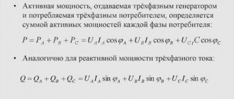
Options for determining ΔU
Vector method
During the design of an electrical network, the basis is the load, the operability of which must be ensured. If the cable is not selected correctly, the ΔU on it will not allow the load to operate correctly. Asynchronous motors will not reach the specified speed, transformers on the secondary windings will not provide rated voltages, etc., etc. For a single-phase network, the load is divided into active and reactive components.
A three-phase network is represented as three independent single-phase networks. They are called equivalent circuits. This method provides fairly accurate results if the load is symmetrical. If the symmetry is broken, then an analysis of the reasons that caused this process can also be performed using this method. Based on known quantities, you can construct a vector diagram and, by changing the length of the vectors according to the task at hand, determine the quantities that are necessary.
Scheme 1
For example, the parameters that are necessary for normal operation of the load are known. The line parameters are also known. Consequently, the task comes down to determining the vector voltage U1. The steps leading to the appearance of the desired vector are shown below.
Scheme 2
The length of the vector and its direction are determined based on Ohm's law and the direction of the voltage vector that determines the current (the current and voltage vectors coincide in direction). The voltage vector, which is obtained as a result of the addition of the active and reactive components of the load (IR + IХ), is ΔU in the line connecting the voltage source U1 with the load. From the obtained vectors it is easy to also obtain the voltage losses. To do this, vectors U1 and U2 are combined so that the direction of both is the same as that of vector U2. The difference between them is in length - this will be a voltage loss.
Diagram of voltage drop and loss Determination of ΔU and voltage loss
Knorring tables
But constructing vectors is quite tedious. Moreover, since the need for designing electrical networks has existed, faster solutions have been invented for standard situations. These include Knorring tables. The standard situation for them is the constant voltage at the input of the cable or other conductor (alternating voltage with an effective value of 220 V)
This is important for both single phase and three phases. That is, in a three-phase electrical network, the load must be symmetrical
It is also necessary to have the cross-sectional area of the conductor (in square millimeters), the length of the conductor (in meters) and the load power (in kilowatts). We get the product of power and length, in the column starting with the appropriate cross-section of the core, we find this value, and in the leftmost column we look at ΔU on the cable. That's all. Two versions of tables for the voltage of a single-phase and three-phase electrical network, as well as one for a voltage of 12 V, shown below, can be used by the reader for calculations.
Table 1 Table 2 Table 3
For all tables, a restriction is accepted - the cores must be made of copper. If the reader comes across such a definition as load torque, this will be exactly the number from the Knorring table for a wire, corresponding to the product of power and length.
Accurate calculations using formulas
If for one reason or another the vector method and tables are not suitable, you can use either the formulas shown below or an online calculator based on them. There are many such calculators on the Internet, and finding the right one is not difficult.
Calculation using formulas ΔU along cable length