After a major overhaul of electrical wiring in a building or when laying new electrical networks, the need arises to reliably protect conductors from overload, as well as to increase their service life. This enables reliable operation of electrical appliances. For protective purposes, circuit breakers are used that cut off the supply of electricity to the consumer when a specified power is exceeded or in the event of a short circuit. These devices are installed and connected in a distribution board. In this article we will talk about how to connect machines in a panel using a comb and jumpers.
Jumpers in the electrical panel. Which wire to use
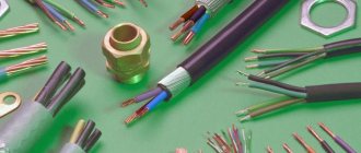
Brands and wire sections for assembling an electrical panel.
What design features should a conductor have? In the power supply of any facility, from utility rooms, warehouses, to high-tech industries, it is impossible to do without electrical panels. The shield itself contains switching equipment and automation, as well as means for distributing and connecting consumers to the power supply network. In simple terms, the switchboard can be an input distribution device (IDU) or an automation and control panel. For normal operation of the system, it is necessary to use installation wires of appropriate quality in compliance with the conditions for their laying and installation.
General principles for wiring in the panel
The switchboard contains all the equipment and mechanisms for connecting consumers to electricity. For its proper operation and safety, it is important to use suitable wires and high-quality parts, because due to a malfunction, users may be left without light, or a fire may even start. The function of conductors in an electrical panel is to connect controllers, indicators and other devices. The entire panel, including the metal casing, must be reliably grounded. Ideally, you should also put a lock on it so that unauthorized people do not have access to the equipment.
The connection must be made in such a way that the connecting wires do not sag. To do this, you need to carefully measure the distance between the connection elements and cut off a few centimeters more so that they can be inserted into the terminals. You cannot save on this, and if the calculations turn out to be incorrect, it is better to repeat the operation.
What does an electrical panel consist of?
The input cable is connected to the electrical panel through holes in the housing, then connections are made to the electrical equipment in accordance with the diagram. For example, when assembling a switchboard, the power cable is connected to the input circuit breaker, and the corresponding equipment that belongs to each consumer group is connected to it.
Inside a modern home electrical panel there is a large number of different switching and protective devices and other types of equipment, including:
The electrical panel body must be grounded, as well as its metal doors and other live parts. To restrict access by unauthorized persons and prevent electric shock, it must be locked with a key.
Basic connection diagrams for circuit breakers in distribution boards
This diagram shows the connection of machines in a single-phase network; circuit breakers 4-7-8-9-10-11 are logically connected with a single-pole bus.
| Name | Price |
| Comb bus 1-phase 63A (1m) | 600 rub. |
| PIN bus 3-phase 63A (1m) | 1600 rub. |
| Copper busbar 3-phase 100A (1m) | 1400 rub. |
One of the disadvantages of a bus connection is the high price; it must be borne in mind that the reliability of the connections ensures long-term trouble-free operation, which completely pays for this cost.
In this scheme, it is recommended to place the RCD and circuit breakers on the same DIN rail and connect it at the input with a four-pole bus.
What should the wire be like?
The requirements for cable products of any type are determined from the conditions in which they are used and laid. In an electrical panel, due to the limited space during its assembly, there is a need for compact routing of wires. Therefore, during assembly, the wire for the electrical panel is bent in accordance with the diagram to connect the functional elements. This implies that the wire must withstand bending normally, so aluminum conductors are poorly suited for this purpose - they break after several bends. Therefore, preference should be given to copper conductors.
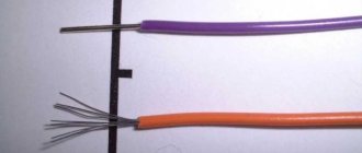
Wires are distinguished by flexibility class, which depends on the design of the cores - monolithic (single-wire) and multi-wire. Solid cores, although difficult to bend, can be directly connected to terminals and screw terminals. In addition, flexibility after installation in the electrical panel is not required.
It is more convenient to work with a flexible stranded conductor during assembly, but there is a significant problem - it cannot be used to connect to terminals and screw terminals, which are used in all automatic machines and other equipment. To connect a flexible wire to such a terminal, you need to either tin the end or crimp it with a tip like NShVI or NShVI2 and the like. If you neglect this, the contact will be unreliable and short-lived.
Taking into account all of the above, we can conclude that domestic wires are suitable for installation in an electrical panel:
PV-1 (PuV) – single-wire copper core, single PVC insulation, flexibility class 1.
PV-3 (PuGV) – stranded copper core, PVC insulation, class 2 flexibility - 0.5 to 1.5 mm2; flexibility class 4 – from 2.5 to 4 mm2; Flexibility class 3 – sections exceeding 4 mm2.
PV-4 - stranded copper core, PVC insulation, more flexible than the previous one, depending on the cross-section, PV-4 has 4 or 5 flexibility class.
The cross section is selected in accordance with the currents that will flow through the conductors
It is also worth remembering that there are standard colors for wires according to their intended purpose:
In this case, it is necessary to carry out the installation in such a way that there is no sagging of the wire (this especially applies to multi-wire conductors) and unnecessary kinks (this applies to monolithic conductors).
To do this, you should determine the required length of the wire in advance, and then cut it 2-3 cm longer to ensure normal insertion of the end into the terminal of the machine.
Connections in the distribution board with the input circuit breaker of a group of consumers are made using jumpers between adjacent circuit breakers; for this you can use both flexible and rigid wire with a single-wire core, but the latter is more convenient, since you do not need to use NShVI lugs. It is better to avoid jumpers altogether if possible and use a connecting bus. It is rigid, the contact will be good, and the installation will be visual and aesthetic.
Source
Squeeze
The clamping method is the most accessible way to connect wires. Its principle is quite simple: the conductive cores of cables or wires are pulled together, compressed, with each other using various types of connectors (screw, spring, etc.). The most striking representative of this method of connecting wires are terminals.
Terminals for connecting wires when installing electrical wiring are most often either screw terminals - where the wires are tightened in a common block with screws, or self-clamping - in which the wire wires are clamped between spring-loaded plates.
Screw terminals are most often used to connect electrical equipment; they are not used when connecting cables in junction boxes. One of the main disadvantages of a screw connection is that over time the contact weakens and the screw must be tightened. If this is not done, the connection point will begin to heat up and as a result, this may cause a fire or unstable operation of the electrical network.
Self-clamping terminals, based on a flat-spring clamp (fasteners under spring plates), are ideal for connecting cable cores or wires when installing electrical wiring. In order to connect the wires, it is enough to place the bare wires into the terminal connectors, where they will automatically lock and be connected to each other through the conductive material of the internal terminal mechanism.
And although such a connection is not as reliable as welding, it is used very often when installing electrical wiring. Primarily due to the simplicity and speed of installation. It is enough just to remove the insulation from the cable cores and place them in the terminals.
The main disadvantage of this connection method is the need to purchase high-quality self-clamping terminals. In addition, such connections manifest themselves rather ambiguously in many extreme situations that, unfortunately, can arise during the operation of the electrical network.
Experienced electricians try to use self-clamping terminals only for lighting groups, and connect cables going, for example, to sockets, by welding.
If you decide to do the wiring in your apartment yourself, then connecting with self-clamping terminals will be the most preferable option for you. The main thing is to use terminals specifically designed for switching power circuits and designed for this. Another advantage is that such connections do not need to be additionally insulated, which also saves a lot of time.
There are also terminals with a lever clamp, in which the core is fixed when the lever is closed, and when it is opened it is released again. Such a terminal can be used many times, but they are quite bulky and expensive, so they are rarely used for connections in junction boxes. Their main advantage over self-clamping terminals is the ability to connect stranded wires without additional preparation of the cores.
Comments and reviews (15)
Edward
It's better not to take risks. Make 4 square meters of wire. From 6 sq. There is also no point in doing this unless you have a 10 kW load on one machine
Konstantin
Once is possible. Either the shield will eventually burn out, or the hut will. But then, having seen live the results of savings “on matches”, such questions will no longer exist. In general, I was always surprised by the approach of the owners - buy a box for 1-5-15 lyams and then tremble over every penny when laying the engineering (electrical, plumbing, ventilation)
Cossack
By jumper the author probably means connecting the input output to other machines. Then, when using 2.5 squares, the total load is no more than 27 Amperes.
Alexander
The person who asked the question is clearly not friendly with electricians. Therefore, the most optimal thing is to use a comb, otherwise with jumpers made of wires of different sections, you will most likely end up with a bad contact (didn’t press, didn’t tighten it, was afraid to break it, etc.), which leads to failure of the machine (usually burns out contact is usually outside, but it also happens inside, and it is not visible to an untrained eye.)
Alexei
In my work I use a connecting comb. If there is no comb, then the cross-section of the jumper should be equal to the cross-section of the supply conductor. In other cases, you will not be able to make reliable contact.
Tiger
You need to take a PuGV wire of 6 squares, crimp it with NShVI lugs, conveniently mount it without hemorrhoids, close the shield and forget it.
Andrey
Makarov Dmitry (Expert)
Since in practice there is a power limit for the consumer, and the machines you indicated do not change anything, you can set it to at least 200 A. As I wrote in the answer, the cross-section of the conductors is selected according to the nominal value of the total load of the electrical equipment connected to the network. If the amperage consumed by the devices does not exceed the permissible limit for the selected wire cross-section, then it is perfect for connecting machines with a comb. From the load value, in turn, the nominal value of the machine connected to a specific line is selected.
Since the rating of the installed machine is a secondary indicator determined by the power of the devices, there is no need to guess it. You can indeed install a 100 A circuit breaker for a network with a maximum load of 15 A, but these are already problems of choosing and setting up protection for household consumers.
That is why, in answering the question, I do not recommend starting from any guesses about possible machines, but give advice on how to correctly calculate the possibility of using a specific wire to connect electrical equipment. Regarding the factory comb and what it is, I also said in my answer, you either did not read it to the end or were simply inattentive.
Install a comb tire and don't bother. Its permissible current is up to 63 A, so it’s more than enough.
Sergey
Alexander
I have this. It used to be jumper wires. As a result, poor contact and burning of the first machine in the row, which included the input from the RCD. The wire entrance to the RCD was from above, and from below it was brought up to a row of machines and compressed by a jumper made of a monolithic wire to a number of machines. The solution is simple, take the first machine in the row where you need a comb, with double input. They can insert both the wire and the comb simultaneously under one screw but in different mounting locations. The wire and comb will not interfere with each other and are clamped tightly. The rest of the machines can be used without double input, only the comb will already be running.
Makarov Dmitry (Expert)
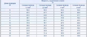
The permissible cross-section by quadrature is determined based on the connected load. If you have a 6mm2 cable installed at the input, then further redistribution from the input circuit breaker between other sections can be carried out with a 2.5mm2 copper conductor, if such a reserve is sufficient for the flowing current. The correspondence of the cross-section and the connected load can be compared in this table:
As you can see, if you had a water cable with a core cross-section of 6mm2 that could withstand a current of 46A or a load of 10.1 kW, then the planned wire with a cross-section of 2.5mm2 can normally pass through only 27A of current load or 5.9 kW of power . This does not mean that the selected 2.5mm2 conductor will not be able to perform the functions assigned to it, but you must first calculate the connected load to ensure the safety of such a connection. Otherwise, you risk causing a fire in the wiring and the switchboard itself.
However, the use of a conductor is not a panacea for wiring in a distribution panel; electrical installation specialists recommend installing a special comb that fully complies with all the requirements of regulatory documents. You can learn more about this method of connecting circuit breakers and more from the following article on the website:
Source
Currently, I have chosen electrical panels and devices from ABB.
But knowledge of modular and panel products from Schneider Electric, Legrand, Hager allows me to assemble electrical panels from components from any manufacturer. Therefore, when choosing a company, I always go to meet the customer of the shield.
But it should be noted that the prices from these manufacturers are almost the same. The only difference is different series of devices, but even if they are similar in parameters, they are also the same.
Below I will give a comparative calculation of the cost of an electrical panel of different series of ABB and Schneider Electric for one of the orders (the calculation is already outdated, but is still relevant).
Comparison of prices for automatic machines, RCDs, switches from ABB and Schneider Electric.
Electrical panels, at the request of the customer, can be equipped with various additional “wants” and protections: light indicators, digital voltmeters, contactors with on/off switching of all or part of the load, timers (time relays) for turning on the load according to a schedule, voltage control relays, etc.
Wire selection
When installing protective devices into the shield, it seems that there is a lot of space left inside, but this is not the case. It will be completely occupied by the wire for assembling the shield and outgoing cables. Therefore, it is necessary to choose wires with a minimum diameter.
This requirement is met by copper conductors, which have a smaller cross-section at the same permissible current compared to aluminum conductors.
In addition, aluminum wires are more likely to break off when connected, so when using aluminum wire to assemble an electrical panel, it is necessary to leave a larger length reserve, which additionally “eats up” free space.
Required Tools
Stripper for removing insulation
To reliably make a connection in the panel, you need to purchase special tools in advance. They must be professional and have insulated handles. Required tools include:
- Hammer.
- Bulgarian.
- Screwdrivers, including an indicator screwdriver for checking the absence of voltage on the wires.
- Knife.
- Device for stripping insulation.
- Pliers.
- Wire cutters.
- Portable lamp.
After preparing the tool, you can begin installation.
Connect wires of different sections using bolts
Another way to connect wires of different sections to each other is to create contact using bolts, washers and nuts. According to professional electricians, this connection is the most durable and strong. The process itself is not too complicated and takes minimal time. The procedure goes as follows:
This continues until all the wires are connected to each other. After putting on the last loop and the last washer, the structure is firmly tightened with a nut.
Which is better: rigid or flexible wire when installing a distribution panel?
The main difference between a rigid wire used for an electrical panel and a flexible one is the ability of a flexible wire to bend in the desired direction up to 12 times (decreases over time), as well as the ease with which it bends.
As a rule, to connect automation in the distribution board, professional electricians use flexible wire PuGV. Because it is more convenient to work with it. For work carried out independently by residents or unskilled workers, rigid wire is often used.
In both the first and second cases, the required build quality can be achieved. However, a wiring diagram assembled using a flexible wire looks more aesthetically pleasing.
Application of aluminum cables for installation of automation
It is not recommended to install automation in a distribution panel, connecting it with aluminum wire, due to:
- low strength (breaks when bent);
- Twisted aluminum wires are almost impossible to solder and very difficult to weld. This leads to a high probability of contact failure over time.
- With equal cross sections, it is capable of passing smaller currents;
- in accordance with the requirements of the PUE (clause 7.1.34 - Cables and wires with copper conductors should be used in buildings).
However, if you can find 8030, 8176 aluminum-iron alloy wires, you can use them. These grades have improved mechanical properties. The manufacturer claims flexibility 6, the highest class. This was achieved by changing the structure of the existing crystallization lattice of the material.
Such a wire can be bent at an angle of up to 90° for 15 times without damage.
The material has a number of significant advantages over copper:
- the alloy weighs significantly less (by about 60%);
- this wire is almost 70% cheaper than copper wire, designed for the same current and power.
Therefore, starting from October 16, 2017, the Ministry of Energy allowed the use of aluminum (in this version) in the installation of electrical wiring in apartments and residential buildings. The basis is order No. 968.
Color coding and jumpers of machines
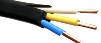
The color of the shell also plays an important role. You need to pay attention to this, because black, red, brown, purple, gray, pink, orange, white and turquoise are phase colors. The yellow-green shell indicates that this is a protective or zero protective shell that can be used for grounding. If blue is added to this color, it is a combined working and zero color. If the wire is just blue, it means the conductor is zero working or average.
Jumpers are installed between adjacent machines. For connection, you can use both single-core and multi-core materials, but the former will still be more convenient - they do not need to be pressed.
Nowadays it is increasingly recommended to avoid jumpers and use special tires that, due to their rigidity, will ensure good contact. An additional advantage of the tire is that it looks very neat.
To make the right choice of components, you need to take into account the material and calculate the amount of voltage that will pass through the conductor. The cross section and even the color of the shell play an important role. The wrong choice of material can lead to many disastrous consequences, so it is best to delegate the task of creating the wiring to a master who can confirm his professionalism.
It is not difficult to carry out the wiring of household electrical wiring, as well as the same ventilation in a private house, yourself according to the instructions above. The main point here is the preparation of the project with all power calculations and core sections, as well as the assembly of the distribution panel. And even a novice electrician-installer can lay wires around the cottage and connect them to sockets.
Watch also the video on how to make electrical wiring with your own hands:
Carrying out installation work
The main thing when performing electrical installation work is compliance with safety rules. Always operate with the power switched off.
Connecting the plug and socket
To connect the plug, strip the wire from the oven or stove; if the wire is stranded, then crimp it with NShV lugs and pass it through the plug body. Mount the phase and neutral on the outermost contacts of the plug. Yellow-green grounding conductor - on the middle contact. To prevent the wire from dangling inside the plug, clamp it with a clamp and tighten the plug body.
The socket is connected in the following way: the socket is mounted in the required place, the socket body is removed and the power line is connected to it. Mount the phase and neutral on the outermost contacts of the socket. Yellow-green grounding conductor - on the middle contact. Next, screw the socket housing.
Cable connection diagrams for the oven and hob
There are two main circuits for connecting an electric stove or hob: single-phase and three-phase. The connection is made to the terminals of the hob, which can be accessed through its back cover - it is unscrewed and removed. Pay close attention to the color markings on the terminals - this will allow you to avoid mistakes, read the connection instructions and safety requirements.
Single-phase 220V circuit (most common in apartments)
Phase L is simultaneously connected to terminals L1-3 of the hob. To do this, two removable copper jumpers are installed between them at the manufacturer. If for some reason you don’t have jumpers, you can make them yourself from an electrical cable whose cross-section is no less than that of the supply cable. Zero N is connected to terminals N1-2. Protective conductor PE – to the PE terminal.
Three-phase 380V circuit (common in private homes and businesses)
Phases A, B, C – are connected to terminals L1-3 of the hob. In this case, it is necessary to remove the jumpers installed at the factory between terminals L1-3. Zero N is connected to terminals N1-2. Protective conductor PE – to the PE terminal.
Connecting the oven is much easier. Most often, such devices are already supplied with an electrical cord with a plug for connection, so the Euro plug is simply inserted into a Euro socket. To connect to machines or terminals, it is best to use a separate cable, since if you cut off the plug on the cable from the kit, this can significantly affect the warranty for this device.
The oven connection diagram is always single-phase:
- Phase L is connected to terminal L of the oven;
- Zero N is connected to terminal N;
- Protective conductor PE – to the PE terminal.
Tags: machine, beat, sconce, view, choice, house, , clamp, protective, sign, isolate, insulation, cable, how, design, contactor, , , marking, installation, power, multimeter, voltage, rule, principle, wire , start, , work, size, calculation, relay, repair, socket, switch, light, connection, circuit, ten, type, current, three-phase, , phase, shield, electricity, electrical panel, effect
Making electrical wiring | Electrician tips
The main connection methods are twisting and terminal clamps (screw, PPE, Wago, etc.). There is also a bolted connection, but it is used very rarely.
All of the above connections fully comply with the Rules for the Construction of Electrical Installations (PUE) - all regulatory authorities - energy supervision, energy sales, and electricity supply organizations - are guided by the same rules.
As for twisting, it should be clarified - this means twisting followed by welding or soldering.
Let me look at these connections in more detail. Read more “How to connect wires in a junction box - disconnection. Video tutorial.”
Despite the variety of types of electric stoves and their wide range, the connection diagram for an electric stove is almost always standard - for built-in stoves, for stationary industrial stoves, and for household ones.
Almost all electric stoves can be connected to both 380 Volts and 220 Volts.
If you purchased an electric stove and don’t know how to connect it, I will show you how to connect an electric stove using a practical example .
Continue reading “How to connect an electric stove”
I find the topic of lighting control from two places .
Imagine: you go into a house, turn on the light in the hallway, then go up to the second floor and turn off the light from there. That is, you don’t have to go down to turn off the light! Very convenient, but how to do it?
For this, there are special switches or, more correctly, pass-through switches .
To do this, you need to know the wiring diagram for the pass-through switch .
Now I will tell you and show you how to connect a pass-through switch and assemble its circuit in a distribution box. Continue reading “Wiring diagram for pass-through switch”
I continue the series of lessons on connecting switches and this time I will tell you and show you on video how to connect a two-key switch .
In apartments, such switches are installed mainly on chandeliers; when one button is turned on, the first group of lamps lights up, and another button lights up the second group of lamps.
The number of lamps in groups can be different - from one to 10 or more lamps. But there can only be two groups. Read more “Connection diagram for a two-key switch”
So, the final stage of work after installing the input cable and installing the apartment panel is assembling the electrical wiring diagram, connecting the machines and RCDs in the panel .
As I already said in the previous article , I divided the electrical wiring in the apartment into three groups and installed its own circuit breaker for each group.
Group 1 - automatic machine for 16 A - rooms, corridor. Wire AVVG 2x2.5 (old wiring)
Group 2 - automatic machine for 20 A - kitchen. Wire VVGng 3x2.5
Group 3 - automatic machine for 16 A - bathroom. Wire VVGng 3x2.5
Continue reading “Replacing electrical wiring in apartment-3”
So, the input cable was secured in a metal hose along the entrance wall; fortunately for us, when drilling, not a single wire was found under the plaster)))
I talked about it HERE .
We breathed a sigh of relief and moved on.
Now the task is to think about how the apartment panel with automatic devices will be attached and how to connect the wires from the new and old electrical wiring to it.
We bought a plastic shield with 6 modules, wall mounting , external design. It would not be possible to build it into the wall since the partition is very thin - only half a brick. But in order to deepen it at least a little, they removed a layer of plaster. Continue reading “Replacing electrical wiring in apartment 2″
When replacing electrical wiring in an apartment, first of all you need to think about the condition of your input cable.
This is especially true if the entire electrical wiring - it is better to put the input cable in order immediately than to do it after the repair.
What does it mean to put things in order?
If the input is made with aluminum wire, it is better to immediately change it and lay a copper cable from the floor panel to the apartment panel or distribution box.
In general, the aluminum wire should be removed as soon as possible and replaced with copper.
It is important that the cross-section of the input cable cores corresponds to the expected load and rated current of the input circuit breaker.
For example, with a load of 7-8 kW, the input must be made with a copper cable with a cross-section of at least 4 sq. mm and the machine must be set to no more than Inom = 40A
Here's how I replaced the input cable in the apartment: Continue reading “Replacing electrical wiring in apartment-1”
I want to tell you a case from practice, especially a very instructive case, since I observe this very often.
It all started with a call from a client I knew for a long time; we went to school together.
The woman is very impressionable, naturally she doesn’t understand anything at all about electrics, she calls and, almost wailing, tearfully asks to come and make light for her in the apartment.
From the verbal waterfall that fell on me from the phone, I realized that something terrible and catastrophic had happened... Read more “Woeful electrician or how NOT to install automatic machines”
In houses with PC-type concrete floor slabs (with air channels inside the pipe), it is possible to install hidden electrical wiring inside the slab.
Wires are laid there for chandeliers, lamps, and even lines for sockets if necessary.
Now I will show how we changed the wire going to the chandelier from the junction box. Continue reading “Installation of hidden electrical wiring to a chandelier”
Main process
We immediately draw your attention to the fact that the article provides instructions for assembling a 220 V switchboard. If you want to assemble a three-phase switchboard, read the separate instructions to which we have referred!
Step 1 – Create a circuit
To begin with, you must create a connection diagram for all machines, meters and distribution buses in order to quickly and correctly assemble a distribution panel in an apartment (or country house). At this stage, you must also choose the most suitable location for installing each product on the DIN rail. The more compact and logical the machines are arranged, the more you will save connecting wires and make the box convenient for maintenance.
For your attention, here is an example of how a diagram for assembling a switchboard in a 220V apartment should look like:
In your version, everything may be completely different, and this will not indicate that the diagram was drawn up incorrectly. In each individual case, you can assemble a switchboard in your own way.
Step 2 – Prepare materials and tools
Among the tools you will definitely need:
multimeter (to test the wiring after connecting all the elements). a set of screwdrivers (tighten the screws on the terminals). an insulation stripping tool or, as a last resort, an electrician’s assembly knife. screwdriver (attach the box to the wall)
As for the elements of the circuit, you must choose everything yourself, depending on the total load on the electrical wiring, the voltage in the network (1 or 3 phases) and the branching of the created circuit. We recommend that you familiarize yourself with the following block of articles, which are closely related to self-assembly of a switchboard:
How to distribute the load across phases How to divide electrical wiring into groups How to draw up a wiring diagram before repair
After reading these articles, you can go to the store for suitable automation and materials, after which all that remains is to assemble the switchboard with your own hands.
Step 3 – Assembling the electrical panel
Now we come to the most important part of the article. Now that you already know what the “filling” of the box will consist of and how to select each of the products, you can proceed to assembly
One very important nuance should be noted right away - you must agree with energy sales representatives who will install the electric meter. If you are allowed to install it yourself, you can draw up the appropriate document and go to work.
Step-by-step instructions for installing an electrical panel are as follows:
Hang the case on the wall (or install it in a prepared niche). Place the input wires and those coming from each room/powerful electrical appliances into the distribution panel. Strip the wires for a good connection to the terminals. Using self-tapping screws, secure a DIN rail inside the housing, which will serve as a fastener for assembling the entire “filling”. Secure all circuit breakers, RCDs and even the meter (if its mountings are appropriate) to the installed strip. Everything is simple here, the design of the shield includes a special latch that quickly and effortlessly snaps the product onto the rail. Install the neutral and ground bus. Cut the connecting wires into suitable lengths. Connect all the elements together according to the diagram. Do not forget that the input phase and zero for circuit breakers and RCDs must be connected to the upper terminals. We talked about how to connect machines in a panel in a separate article. Carefully check the quality of assembly of the distribution board, if necessary, re-tighten the screws on all terminals. Invite an energy sales representative to seal the electric meter. Check the correctness of the work performed by turning on the input machine.
If, after you turned on the electricity, the characteristic burning smell did not appear, sparking did not occur and the RCD did not trip, then all electrical installation work was completed correctly.
Visual video lesson of the entire basic process:
Correct assembly
Finally, we recommend that you familiarize yourself with some simple tips that will help you more correctly assemble a switchboard in an apartment or private house.
General information on the structure and material of cable cores
Here, the information that many people have is limited only to the difference between aluminum and copper cable. Moreover, it is quite meager and, at times, erroneous. The fact is that aluminum, in addition to its short service life, is also very unreliable. It is enough to bend it several times and the core will break. Its only advantage is its low cost, but this criterion in electrical engineering should be in last place, which means we should stop at copper.
Copper cables and their modifications
Such conductors are ideal not only for assembling distribution boards, but also for any electrical installation in general. However, we should not forget that such cables can be rigid and flexible. The latter are much easier to install, but are more expensive. Another disadvantage they have over rigid conductors is the impossibility of fixing them in screw terminals without prior preparation. We are talking about tinning or crimping with a tip using a crimper.
Such conductors must be crimped or tinned before switching
What to choose: the use of rigid and flexible copper conductors in the installation of a distribution panel
If you look from the point of view of convenience, then during installation it is better to use flexible cables, however, even here everything is not clear. When using rigid conductors, their installation is a little more complicated, but at the same time it simplifies the creation of high-quality contacts on connections with automation and buses, both zero and grounding. In addition, having carefully laid everything once, the master will not return to this work again. But when using a flexible cable, the problem arises of poor-quality connections, which will subsequently begin to heat up, which is unacceptable when assembling power cabinets or lighting panels.
Thus, the best choice for installing electrical panels is rigid copper wire of a suitable cross-section. The use of flexible conductors is permissible only in hard-to-reach places with obligatory tinning or crimping of a section cleared of insulation with a tip.
Features of the use of cores when installing an electrical panel
It is especially necessary to pay attention to the mandatory observance of the color marking of the cores when assembling the distribution panel. This is necessary so as not to waste a lot of time in the future when making revisions or repairs. Also, this work can be performed by another installer, which can lead (if the color marking is violated) to electric shock to the technician. Today, Russia has adopted the European color marking system, namely:
For a phase wire, a larger number of colors are accepted due to the fact that there can be three of them. At the same time, he lived in shades in any interpretation. The only thing that is mandatory for it is the presence of blue (sometimes white-blue) and yellow-green wires.
As for crimping flexible cores, various tip options are used here, depending on the contact. When assembling an electrical panel, NSHVI is the most common. It should be noted that crimping contacts using pliers is not allowed - a tight connection cannot be achieved in this way. To perform this type of work, special crimping pliers called crimpers are used. Using such a tool is quite simple, and therefore it does not require any special knowledge or experience. The only thing worth paying attention to is the inadmissibility of bare parts sticking out (when connecting phase conductors). For this reason, it is sometimes necessary to cut off part of the crimped tip.
Application of aluminum cables for installation of automation
This option is budget-friendly, which means it will require minimal costs. But there are features that need to be paid attention to.
What you need to know
There are several types of networks, namely:
- single-phase;
- three-phase.
According to the installation method:
- using a comb, that is, a tire;
- through jumpers made of single-core electrical wires;
- through a jumper made of multi-core electrical wire.
Based on the initial data, it is important to buy technical fittings for installing switches, choosing the required connection option directly to your own electrical network.
Installing a single-phase circuit is not too different from installing a three-phase method. So, in the first case, only one phase is supplied to the output of the switches, and single-type switches are used.
As for the three-phase circuit, triple-acting switches are used here when connecting three-phase voltage, or you can install single ones for all phases individually, with single-phase voltage.
Connecting bus comb for automatic machines
Automatic switches, RCDs, difavtomats - all these modular protection devices are used today in a set of modern distribution boards. Such protective devices must be connected correctly, reliably and safely. How do most people do this?
Nowadays, people most often connect groups of machines with homemade cable jumpers, as described above. With careful and high-quality work, such jumpers will last a long time.
But the skill of many people leaves much to be desired. I would like to give a real example of connecting circuit breakers in a switchboard using jumpers.
In one of the houses where I was doing electrical installation (or rather in an apartment), I somehow decided to look into the electrical panel that was installed on the staircase.
What I saw horrified me, since the jumper between the machines was made with bare wire. See for yourself:
Moreover, it seems that all the work in this house was done by the same person (I suspect an electrician from the housing office), the floor above and the floor below are exactly the same picture, everything was done in the same way. Ordinary people are not at all interested in this, and they don’t understand anything about it. What prevented this electrician from making a jumper with an insulated wire, I’m already silent about the use of a comb connecting bus for automatic machines
. This is why you need to pay attention to the electricians who perform the work.
So, we’ve looked at hacks and what not to do, now we’ll look at how to do it correctly.
The essence of the whole design is that pins - teeth - extend from the plate, which is located in a plastic case. The plate and teeth are one solid structure, cast, without joints. The teeth are bare, as they are inserted into the contacts for connecting the protective module. The shape of the teeth can be different - z-shaped, v-shaped (usually g-shaped). The copper plate moves freely in the housing and can be easily removed from there and examined.
This connecting bus for automatic machines is very compact and allows you to beautifully and reliably connect automatic devices placed in one row. Just like automatic circuit breakers, combs according to the number of poles are produced by manufacturers as single-pole, two-pole, three-pole and four-pole.