In conversations with customers when discussing 12-volt halogen lighting, for some reason the word “low voltage” often comes up, which characterizes the appropriate attitude to the choice of wires - we use whatever is at hand, the voltage is safe. A voltage of 12 volts is truly safe, in the sense that touching a bare wire with such voltage is simply not felt, but the currents in such circuits flow quite large (see the main points of using safe voltage in everyday life).
Let's consider, for example, the power supply of an ordinary halogen lamp with a power of 50 W, the current in the primary circuit of the transformer is I=50W/220V=0.23A (or, more precisely, a little more, taking into account the efficiency of the transformer), while the current flows in the secondary circuit of 12 V I=50W/ 12V= 4.2 A, which is already 18 times more. If you do not take this fact into account, you may encounter very unpleasant surprises.
halogen lighting in his house , used a reliable 1000W induction transformer with a 900W load, ran a separate wire from the mounting box to each lamp, but at the moment of turning on the wires simply caught fire, and those wires which led from the transformer output to the wiring box.
To the question about the cross-section of the laid wires, the answer is: “The ordinary cross-section, as everywhere else, is 1.5 mm 2.” In stationary mode, a current I=900W/12V=75A should flow through this wire, and even more when switched on. The cross-section of the copper wire in such conditions must be at least 16 mm 2. Hence the conclusion: it is important not to forget about the increased currents in 12 volt circuits and choose wires accordingly . This, however, is sometimes completely insufficient.
Very often we come across complaints that when using high-power transformers (in this case, 200W is already high power) feeding several lamps, the brightness of the lamps noticeably decreases with increasing distance from the transformer . Attempts to cope with this problem by increasing the power of the transformer, naturally, do not lead to an improvement in the situation, much less increasing the power of the lamps used does not help. The fact is that the cause of this phenomenon is a banal voltage drop on the wires in accordance with Ohm's law .
Let us illustrate this with a specific example:
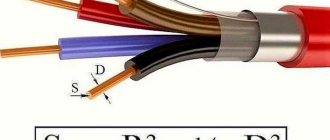
Let's say we need to power a group of three lamps of 50W each, located at a distance L from the transformer, as shown in the figure:
The equivalent circuit looks like:
The resistance of each lamp is Rl = U 2 /P = 2.88 Ohm, and the resistance of the wire with length L and cross-section S
where ρ is the resistivity, in this case of copper (0.0173 Ohm mm 2 /M).
If the transformer output maintains a voltage of U = 12 V, then the current through each lamp
and the power released in the lamp
Using these formulas, it is easy to calculate the dependence of power on wire length . The calculation results are shown in the table (if you click on the picture, the table will load in a larger format):
As can be seen from the table, the power drops quite quickly with increasing wire length ; this can be seen even more clearly in the graphs:
Fig.3. Lamp power loss depending on the length of the supply wires
You can avoid noticeable unevenness of the luminous flux of lamps not only by using a large-section wire, but also by dividing the lamps into groups powered by separate wires, ultimately powering each lamp with its own wire . In any case, when purchasing lighting equipment, it is useful to ask the seller to give precise recommendations on the choice of wire cross-section and installation diagram.
Calculation of cable cross-section for 12 volt DC
The use of low-voltage lighting systems, when the luminaires are powered by a reduced voltage through a transformer, is currently quite widely used.
This growing popularity is primarily due to the high degree of electrical safety of such lighting systems; voltage 12 V is considered to be conditionally safe, which allows the use of low-voltage lighting systems in rooms with a high or increased degree of danger.
However, the reduced voltage of the circuits does not give grounds to consider them low-current: after all, the current flowing in them will be significantly higher than in circuits with a load of the same power consumption and a voltage of 220 V.
Using the formula I=P/U, we find the current consumption of a 50 W light bulb in a 12 and 220 V circuit.
Using simple calculations, we will find the currents for a 220 V and 12 V lamp. In the first case it is 50W/220V=0.23A, in the second 50W/12V=4.2A.
As you can see, the difference in currents in the compared consumption circuits of a 50-watt light bulb is more than an order of magnitude.
Calculation of wire cross-section for 12 volt circuits
To determine the minimum cross-section of a conductor, first of all, using the same formula, it is necessary to calculate the amount of current flowing through it, using data from the total power consumption and supply voltage.
Next, we suggest using the table below:
In this table, the minimum cable cross-sections correspond to the current consumption and the maximum lengths of the secondary circuit lines (taking into account the permissible voltage losses in the line).
Having calculated the current, find in the same column of the table the closest value of the line length and the corresponding value of the minimum conductor cross-section.
- Electrical calculations
- Calculation of wire cross-section at a voltage of 12 volts
Go to the forum
This site has been created for informational purposes only. The resource materials are for reference only.
When quoting site materials, an active hyperlink to l220.ru is required.
A document defining the rules of the device, regulating the principles of construction and requirements for both individual systems and their elements, units and communications of the power plant, conditions of placement and installation.
PTEEP
Requirements and responsibilities of consumers, responsibility for implementation, requirements for personnel operating the power plant, management, repair, modernization, commissioning of the power plant, personnel training.
POTEU
Rules for labor protection during the operation of electrical installations - a document created on the basis of the currently inactive Inter-industry rules for labor protection (POT R M-016-2001, RD 153-34.0-03.150).
Source
Calculation of voltage drop on wires
Selecting wire cross-section for direct current. Voltage drop (explanations in the article)
They say that at one time there was a rivalry between Edison and Tesla - which current should be chosen for transmission over long distances - alternating or direct? Edison was in favor of using direct current to transmit electricity. Tesla argued that alternating current was easier to transmit and transform.
Subsequently, as is known, Tesla won. Nowadays alternating current is used everywhere, in Russia with a frequency of 50 Hz. It is cheaper to transmit such current over long distances. Although, there are also DC power lines for special applications.
And if you use high voltages (for example, 110 or 10 kV), then there will be significant savings on wires compared to low voltage. I talk about this in an article about the difference between 380V and 220V.
Tesla then went even further - he found a way to transmit electric current completely without wires. This caused great dissatisfaction among copper producers. But this is a topic for a completely different article.
By the way, if you are interested in what I write about, subscribe to receive new articles and join the group on VK!
Looking ahead, I will say that the calculation of the wire cross-section for direct current is based on two criteria:
- Voltage drop (loss)
- Wire heating
The first point for direct current is the most important, and the second only follows from the first.
Now in detail, in order, for those who want to UNDERSTAND.
Voltage drop on the wire
The article will be specific, with theoretical calculations and formulas. For those who are not interested in what comes from and why, I advise you to go straight to Table 2 - Selecting the wire cross-section depending on the current and voltage drop.
And also - calculation of voltage losses on a long powerful three-phase cable line. An example of calculating a real line.
So, if we take the power constant, then as the voltage decreases, the current should increase, according to the formula:
P = I U. (1)
U = R I. (2)
From these two formulas it is clear that as the supply voltage decreases, the losses on the wire increase. Therefore, the lower the supply voltage, the larger the cross-section of the wire must be used to transmit the same power.
Wire cross-section for current and power 12v
In conversations with customers when discussing 12-volt halogen lighting, for some reason the word “low-voltage” often comes up, which characterizes the appropriate attitude to the choice of wires - we use whatever is at hand, the voltage is safe.
A voltage of 12 volts is truly safe, in the sense that touching a bare wire with such voltage is simply not felt, but the currents in such circuits flow quite large (see the main points of using safe voltage in everyday life).
Let's consider, for example, the power supply of an ordinary halogen lamp with a power of 50 W, the current in the primary circuit of the transformer is I=50W/220V=0.23A (or, more precisely, a little more, taking into account the efficiency of the transformer), while the current flows in the secondary circuit of 12 V I=50W/ 12V= 4.2 A, which is already 18 times more. If you do not take this fact into account, you may encounter very unpleasant surprises.
halogen lighting in his house , used a reliable 1000W induction transformer with a 900W load, ran a separate wire from the mounting box to each lamp, but at the moment of turning on the wires simply caught fire, and those wires which led from the transformer output to the wiring box.
To the question about the cross-section of the laid wires, the answer is: “The usual cross-section, as everywhere else - 1.5 mm 2.” In stationary mode, a current I=900W/12V=75A should flow through this wire, and even more when switched on.
The cross-section of the copper wire in such conditions must be at least 16 mm 2. Hence the conclusion: it is important not to forget about the increased currents in 12 volt circuits and choose wires accordingly .
This, however, is sometimes completely insufficient.
Very often we come across complaints that when using high-power transformers (in this case, 200W is already high power) feeding several lamps, the brightness of the lamps noticeably decreases with increasing distance from the transformer .
Attempts to cope with this problem by increasing the power of the transformer, naturally, do not lead to an improvement in the situation, much less increasing the power of the lamps used does not help.
The fact is that the cause of this phenomenon is a banal voltage drop on the wires in accordance with Ohm's law .
Let us illustrate this with a specific example:
Let's say we need to power a group of three lamps of 50W each, located at a distance L from the transformer, as shown in the figure:
The equivalent circuit looks like:
The resistance of each lamp is Rl = U 2 /P = 2.88 Ohm, and the resistance of the wire with length L and cross-section S
where ρ is the resistivity, in this case of copper (0.0173 Ohm mm 2 /M).
If the transformer output maintains a voltage of U = 12 V, then the current through each lamp
and the power released in the lamp
Using these formulas, it is easy to calculate the dependence of power on wire length . The calculation results are shown in the table (if you click on the picture, the table will load in a larger format):
As can be seen from the table, the power drops quite quickly with increasing wire length ; this can be seen even more clearly in the graphs:
Fig.3. Lamp power loss depending on the length of the supply wires
You can avoid noticeable unevenness of the luminous flux of lamps not only by using a large-section wire, but also by dividing the lamps into groups powered by separate wires, ultimately powering each lamp with its own wire . In any case, when purchasing lighting equipment, it is useful to ask the seller to give precise recommendations on the choice of wire cross-section and installation diagram.
Specific recommendations for choosing wire cross-section in a 12 V lighting circuit when using electronic and induction transformers can be found in the corresponding tables.
Tables for selecting wire cross-sections in low-voltage lighting circuits
As shown earlier, from the analysis of power losses in 12 V lighting networks, the cross-section of wires for 12 volt halogen lighting should be selected taking into account the total power of the lamps connected to the transformer and the length of these wires.
The approach to determining the wire cross-section depends on what source is used to power the circuit: electronic or induction.
The permissible length of wires in the secondary circuit of electronic power supplies, as a rule, cannot exceed 2 meters (in very rare cases, for high-power transformers, a length of up to 3 meters is allowed).
In this case, you should use a wire with a cross-section specified in the documentation for the transformer . If such data is missing, you can roughly use the data from the table:
Table of cross-sections of copper wires in a 12 V lighting circuit up to 2 meters long (for electronic power supplies). If you click on the picture, the table will load in a larger format.
When using induction transformers, the length of the wire in the secondary circuit is limited only by the voltage drop across the wires and, therefore, can be significantly greater than with electronic (switching) power supplies, subject to compensation by increasing the cross-section of the wire.
Below is a table for selecting the cross-section of the wires depending on the total power of the lamps connected to the secondary winding of the induction transformer and the length of these wires .
It should be borne in mind that lamps can be divided into groups, each connected with its own wire; in this case, the cross-section of the group wire is determined from the table for each group separately.
In the limit, it is possible to connect each lamp with its own wire.
Table of cross-sections of copper wires in the 12 V lighting circuit (for induction transformers).
Calculation of cable cross-section by current: popular information about electric current
During the construction of houses, both private and multi-apartment buildings, office buildings and industrial buildings, for the safe operation of the electrical network and devices, it is necessary to calculate the current cross-section of the cable.
How to make a calculation
How to choose a cable
To calculate the safe and required thickness of an electrical cable depending on the current that will pass through it, you need to know what electrical appliances will be used.
So, further – everything is considered an image.
The power of each device will be required; The formula for calculating the overall power indicator looks like this:
where is Rtot. – the power of all electrical appliances in a house or apartment (in Watts),
P1, P2, etc. is the power of each specific device.
Let’s say that three lamps, a refrigerator, a microwave oven, and an electric kettle will work in a single-phase network. Ptot.=300+200+1100+2200=3800 W. For further calculations, you need to know the current strength, which is calculated by the formula:
where I is the current strength,
U – network voltage.
Now, when substituting all known data, you get:
I = 3800:220 = 17.3 Amps.
Taking into account that the wiring will be made of copper, the resistivity (p) of which is 0.0175 Ohm * mm 2 /m. Let’s immediately calculate the resistance of the circuit section from the following formula:
Now, from the calculation of resistance (take the length of the conductor (L) as a nominal meter), which has the following form:
R=(рL)/S, let’s derive the cross-sectional area.
Accordingly, the cross-sectional area of the cable required for normal operation of the equipment listed above is equal to (0.0175*1000)*1/12=1.46 mm 2 .
Another calculation option
Why calculate the cable cross-section by current and length? In order for the network to function without overvoltage and failures, this stage cannot be skipped.
Cross-section of copper and aluminum conductors
The fact is that each specific conductor will lose power as its length increases. That is, the longer the wires, the greater will be such losses, which are facilitated by resistance.
Based on the formula already described S=рL/R. Everything is known here, except the resistance R. It can be calculated based on Ohm’s law for a section of the circuit (U=I*R) - hence R=U/I. In the example under consideration, R = 220/17.3 = 12.7 Ohms (approximate rounded value - 12).
To calculate voltage losses, you need to divide the resulting U value by the voltage in the network (for example, in a regular household network, most often 220 V). The result is a coefficient that, when multiplied by one hundred, will give the loss value in percentage terms: if it is more than five percent, the cable thickness must be increased.
For accurate, long-term and safe operation of newly laid wiring, especially long ones, it is imperative to calculate the cable cross-section along the length. In this case, you need to take into account what material it is made of.
For example, the length of a copper cable is 5 meters, then S=рL/R=(0.0175*1000)*5/12=7.3 mm (approximate rounded value).
Calculation example
Let's calculate the cable cross-section for a current of 12 volts. Let us assume that various electrical appliances are used (or presumably can be used), namely 12, 12, 30 Watts, that is, P1=12, P2=12, P3=30.
Now, substituting the values into the first formula, we get Ptot. = P1+P2+P3 = 12+12+30 = 54 W. That is, the total power is fifty-four watts. Based on the second formula (I = Ptotal/U), the current strength I is 54/12 = 4.5 Amperes.
Now all that remains is to choose one of the available materials from which the cables are made, for example, copper is used for wiring, and the length is one meter. Using the already mentioned formula, the cross-sectional area can be found using the formula S=рL/R=(0.0175*1000)*1/R=17.5/R, where R=U/I.
Selecting a simple transformer-based circuit
ROMs of any type perform the same task - they help start the car. However, when assembling a starting charger for a car with your own hands or buying it, it is worth remembering that there are several varieties of internal electronic filling:
- working on a transformer;
- delivering energy from a special separate battery (boosters);
- capacitor type;
- pulsed.
Since we are talking about the simplest ROMs that you can assemble with your own hands, we will further consider the first type of circuits listed above.
Selection of cable cross-section for 12 volt current
Selecting wire cross-section and fuse
Wire selection table depending on load current and ambient temperature.
Wire cross-section, mm 2
Permissible current (A) depending on the ambient temperature, C
When choosing a wire, you need to take into account its length and the method of laying it (in a bundle, corrugated or separately). Below is a more detailed table taking into account the length of the wire.
The maximum cable length (in meters) from the energy source to the consumer with a voltage drop of less than 2% for 12V systems. That is, the values inside the table are the length of a wire of a certain cross-section and the current passing through it, at which there will be a voltage drop of 2%.
Cable cross-section, mm 2
For example, when connecting a car radio, we need 1 meter of wire, the current consumption is approximately 10 amperes. Looking at the table, we see (highlighted in green) that we need a wire with a cross section of 1.5 mm 2. (10 - Current, 1 - length, 1.5 - wire cross-section).
When choosing a wire, you must not forget about the fuses; in the event of a short circuit, the fuse should blow, not the wire. The fuse should be located as close as possible to the power source or to a larger rated distribution fuse.
Using the following table, you can roughly select a fuse only to protect the wire where the load will be constant. For loads with large starting currents, for example a starter, a winch, the fuse rating must be calculated taking into account the starting current of the consumer.
The fuse can withstand short-term overloads; if 35% of the rated current is exceeded, the fuse will blow in a matter of seconds or instantly (depending on the manufacturer).
Source
Recommendations for choosing cable cross-section for 12V supply voltage.
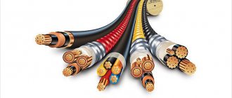
A cable is one or more insulated and twisted cores of conductive material (metals), enclosed in a hermetic sheath, on top of which various protective covers can be applied.
Cable between the 12 V power supply (PSU) and its load (LED spotlights, lamps, RGB lamps).
To accurately determine the cross-section of the wires from the power supply to its load, you need to know the currents flowing through them and the distance from the power supply to the consumer. As a rule, most electrical appliances (lamps, spotlights) have a power consumption value (W) in their markings.
This value will help you calculate the current correctly. So, using the example of one calculation, we will show how to calculate the cable length and its cross-section. Here you need to take into account a very important point: when connecting a long cable, the voltage at its end will differ from the voltage directly at the power supply.
It will decrease by some value ∆U. For an LED lamp, the permissible decrease in the supply voltage is 0.8 V. If the supply voltage is less than 11.2 V, then the brightness of the lamp will be significantly less and this will be noticeable to the naked eye.
It is with this voltage (0.8 V) that further calculations will be carried out.
Example: 12V power supply and 100W LED lamp. The current flowing through the cable for a given system will be determined by the formula
Source
Calculation of cable cross-section by current: we use calculators and tables for calculation
It is now simply impossible to imagine the life of a modern person without electricity. But if you treat yourself negligently, it can become not a friend, but a deadly enemy. Even at the household level, the operation of electrical networks, systems and devices requires strict adherence to a number of immutable rules.
Calculation of cable cross-section for current
And, by the way, one of the most vulnerable places in the area of final consumption of electricity, that is, in residential buildings and apartments, is electrical wiring. Namely, an incorrect calculation of the cable cross-section based on the load current, which is why accidents most often occur with very serious and sometimes tragic consequences.
The problem is often that homeowners simply do not see the connection between the cross-section of the conductor and the power of the connected load: “current flows - and okay.”
There are also situations when contractors clearly “scraped” during construction and, trying to save as much as possible on materials, secretly laid wires that were of poor quality or did not comply with the design.
There are often cases where old wiring continues to be used; it may have been installed correctly, but once upon a time a very long time ago, that is, it is clearly not designed for the modern saturation of people’s lives with electrical household appliances.
This publication will consider several ways to assess the compliance of the conductor cross-section with the actual operating conditions of electrical appliances.
Tables for selecting wire cross-sections in 12 and 24 volt lighting circuits
- 10. Standards for illumination of premises Until recently, regulation of requirements for lighting of premises, buildings, adjacent areas, streets, etc....
- 9. Tables for selecting wire cross-sections in 220 V networks In networks with a voltage of 220 V, the requirements for wire cross-sections are significantly lower than in ...
- 7. Selecting the cross-section of wires in 12-24 volt lighting circuits In conversations with customers when discussing halogen lighting, for some reason very often...
- 6. Calculation of illumination for recessed halogen lamps As an example of illumination calculation, let’s consider the use of halogen lamps,…
- References 1. V.V. Meshkov “Fundamentals of lighting engineering.” Part 1. Gosenergoizdat 1957 2. V.V. Meshkov “Fundamentals...
- 5. “Converting lumens to candella” Information is often searched on the Internet for the query “converting lumens to candella” and vice versa...
- 4. Brightness and luminosity For light sources whose dimensions cannot be neglected (that is, which cannot be considered as point-like), ...
- 3. Illumination The amount of light energy per unit of time (luminous flux) per unit area of the illuminated object...
- 2. Luminous intensity Luminous intensity I characterizes the distribution of luminous flux in different directions and is defined as angular density...
aost1955
In networks with a voltage of 220 V, the requirements for wire cross-section are significantly lower than in low-voltage networks of 12 V, and not only because significantly lower currents flow in them (with the same power), but mainly due to the fact that in In relative terms, a voltage drop of 1 volt in a low-voltage network is much more noticeable in its consequences. Because of this, in 220 V networks, when choosing a cross-section, the voltage drop depending on the length of the wire is not taken into account at all, but only the permissible heating of the wires when a certain amount of current passes through them.
For the convenience of users and for comparison with the requirements for the cross-section of wires in low-voltage 12 V networks, as reference material we provide tables for selecting the cross-section of wires in 220 V networks. These tables are borrowed from the reference book of R.A. Kesarimov. [ 4 ].
Table of permissible continuous currents
(for wires with copper conductors with rubber and polyvinyl chloride insulation)
Cross-section of the current-carrying conductor,
mm2 Current, A, for wires laid
| Open | In one pipe | |||||
| two single-core | three single-core | four single-core | one two-wire | one three-wire | ||
| 2,5 | 30 | 27 | 25 | 25 | 25 | 21 |
| 4 | 41 | 38 | 35 | 30 | 32 | 27 |
| 6 | 50 | 46 | 42 | 40 | 40 | 34 |
| 10 | 80 | 70 | 60 | 50 | 55 | 50 |
| 16 | 100 | 85 | 80 | 75 | 80 | 70 |
| 25 | 140 | 115 | 100 | 90 | 100 | 85 |
| 35 | 170 | 135 | 125 | 115 | 125 | 100 |
| 50 | 215 | 185 | 170 | 150 | 160 | 135 |
| 70 | 270 | 225 | 210 | 185 | 195 | 175 |
Page 3
Charger made from a diode and a household light bulb
A diode is a semiconductor electronic device that is capable of conducting current in one direction and has a resistance equal to zero.
The charging adapter for the laptop will be used as a diode.
To manufacture this type of device, we will need:
- charging adapter for laptop;
- bulb;
- wires from 1 m long;
Each car charger produces about 20V voltage. Since the diode replaces the adapter and passes voltage only in one direction, it is protected from short circuits that can occur if connected incorrectly.
The higher the power of the light bulb, the faster the battery charges.
Work progress:
- to the positive wire of the laptop adapter .
- From the light bulb we throw the wire to the positive.
- the negative from the adapter directly to the battery.
If connected correctly, our light bulb will glow because the current at the terminals is low and the voltage is high.
Based on this, you can connect a high-power light bulb only in special cases.
This method involves constantly monitoring and measuring the voltage at the terminals. Overcharging the battery will produce excessive amounts of hydrogen and may damage it.
When charging the battery in this way, try to stay near the device, since leaving it temporarily unattended can lead to failure of the device and the battery.
Checking and setting
To test our device, you must have a working car light bulb. First, using a wire, we connect our light bulb to the charger, remembering to observe the polarity. We plug in the charger and the light comes on. Everything is working.