Technical specifications on the contactor itself
Let's start with the contactor from Schneider Electric. The maximum possible power connected to the contactor in horsepower (HP) is indicated on the side edge. This power depends on the supply voltage.
In a number of countries, horsepower is still used, although there are recommendations from the international metrology organization that horsepower should be eliminated from use.
The following are general recommendations for selecting circuit breakers or fuses.
- the inscription CB - Circuit Breaker refers to automatic machines
- Fuse – to fuses
The maximum operating voltage (a.c. max) must be specified.
Cont. current is the continuous rated current at load category AC1.
To put it simply, category AC1 is a load such as an iron or an ordinary heater.
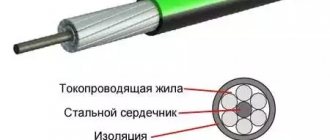
AWG 6-14 Cu - shows the cross-section of wires that can be connected to the contacts.
Measurements are in Western units. In order to find out the analogue of our section in mm2, you will need to use the AWG to mm2 conversion table.
Torque 20lb.in – the torque with which the terminals can be tightened.
More accurate numbers in conventional units of measurement can also be found in the technical data on the manufacturer’s website, or use a special program here that converts lb-in to Nm (newton meters).
Lb-in stands for pounds per square inch.
High-quality contactors always have inscriptions indicating the presence of certificates to which this mechanism corresponds.
Ith-40A – conditional thermal current in open design. Simply put, this is the current that the contactor can pass through itself under normal environmental conditions.
Ui=690V – rated insulation voltage of the product.
IEC/EN 60947-4-1 – starter compliance with this standard. GOST R50030.4.1-2012 is our modified analogue of this standard.
Uimp=6kV – permissible pulse overvoltage.
A separate plate indicates the possible powers connected to the contactor, depending on the supply voltage.
Powers are already registered in kilowatts. Some may wonder why there is such a difference depending on the voltage.
This is explained simply. By and large, the contactor does not care what voltage the load is designed for. The most important thing is the amount of current flowing through its contacts.
For example, you have a voltage of 100V and a current of 10A. The load in this case will be 1 kW.
And if the voltage is 2 times greater, i.e. 200V, then when connecting the same load of 1 kW, a current will flow through the product 2 times less than I = 5A.
Therefore, the lower the voltage, the less power the load can be connected to the contactor. At the same time, always pay attention to what type of load the data is indicated for.
For example, in this case, the powers are indicated for the AC3 load. An example of such a load is an asynchronous motor.
JIS C8201-4-1 is a Japanese industrial standard. Accordingly, the possible powers connected to the contactor are also specified here, depending on the supply voltage according to this standard.
Why is such a large and strange set of voltages prescribed? Because different countries have different standards that determine power voltage levels.
For example, in Japan, a regular outlet has 100 volts. And for powerful loads, 200V is already used.
Contact labels
Let's move on to the inscriptions on the front panel of the starter = contactor.
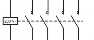
A1 and A2 are the control coil connection points.
The terminals themselves are marked in two alternative ways:
- number sequence 1-2-3-4-5-6
- alphanumeric. Top L1-L2-L3. Bottom T1-T2-T3.
Auxiliary contacts are marked in accordance with standards. There is one nuance that not everyone knows about.
Normally open and closed contacts
The first digit of the designation is the serial number of the contact. And the second digit is the contact function.
For example, at the top you can see the inscriptions 13-21. Bottom 14-22.
That is, the first numbers 1-2 are the serial number of the contact. There is one auxiliary contact on the left, and a second on the right.
And the second number is the function. The number 1-2 is the common wire or part of the normally closed contact of the circuit.
The number 3-4 is part of the normally open contact. That is, by looking at the numbers, without unwinding or ringing the mechanism, without studying its diagram in the passport, you can immediately understand that 13-14 is normally open contact No. 1 (NO - normal open).
A 21-22 – normally closed contact No. 2 (NC – normal closed).
All other electromagnetic relays familiar to us have the same markings, making it easier to visually understand the functionality of the device. Here is an example of another relay and the designation of its contacts.
You don’t need to look for documentation for it to understand how to connect here or what function this or that screw terminal has.
The voltage of the coil that controls the starter is also required to be written on the housing.
The letter M7 (or another) is a definition of the coil type in the order number.
For example, if a coil burns out in your LC1D25 contactor, you will only need to indicate the voltage and its number M7 when ordering. You will know for sure that exactly the product will arrive, and the size you need.
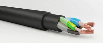
Another important point that is worth paying attention to is the possibility of using different types of wires in the terminals. If the pads are copper, this means that it is unacceptable to use aluminum wires.
The cross-section and types of connected wires are indicated in the technical documentation.
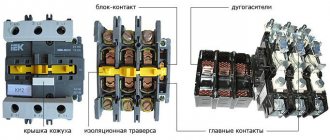
Contactor IEK
With the IEK contactor everything is much simpler. Its marking is based on almost the same principle.
Alphanumeric designation of working terminals:
- L1-L2-L3 (1-3-5)
- T1-T2-T3 (2-4-6)
Double marking of auxiliary contacts: 13-14
- first group (first numbers 1-1)
- with normally open contact (second digits 3-4)
For the Russian market there may be an abbreviation “NO” - normally open.
The coil voltage of 230V (50Hz) is written on the side. And other technical parameters.
KMI – 10910 – its order number
AC-3 In=9A and AC1 In=25A – possible connected load for various categories.
The power of the connected load is also indicated depending on their supply voltage.
Even a schematic diagram of a contactor with all its contacts (working and auxiliary) can be depicted.
Below is written the regulatory document to which this product corresponds - GOST R50030.4.1
Source
Share the news on social networks
- Related Posts
- Electrical panel diagram in the apartment - connection of machines, uzo
- Why does the LED lamp blink when the lights are off and what to do?
- Which electric meter to choose for an apartment or house
« Previous entry
How to choose a contactor
The larger the device, the more powerful the load it can handle. It is important to pay attention to the fact that the coil voltage is equal to the control voltage, and the contacts can withstand the load when connecting all consumers. There are 3 classes of switching wear resistance of such devices (A, B and C). It is better to choose a product with a small supply of this parameter.
Before selecting a contactor, it is important to have an understanding of the operating conditions. Based on this, the optimal degree of protection is selected. For example, if the equipment will be located in an electrical cabinet, then it is enough to purchase a model with a degree of protection IP20. For dusty rooms or objects with high humidity, you should choose more protected enclosures (IP45 or 65). A protection module equipped with a thermal relay can save you from overloads.
What do the abbreviated names of starters mean?
Below are explanations of the symbols and names of popular brands of starters and contactors PML, KME, PAE, PMA.
From them you can find out what certain alphanumeric symbols mean and how they are deciphered.
It turns out that just from the name alone you can understand:
- what product is this
- what functionality does it have?
- what additional capabilities does it contain?
To view each starter type, click on the appropriate tab.
PMLKMEPAEPMA
However, in addition to the name, a lot of information is contained on the contactor body itself.
Let's look at the example of two products from IEK KMI and Schneider Electric LC1D25, what inscriptions and designations manufacturers put on the housings, how they are deciphered and what they mean.
Graphics and symbolism in single-line diagrams
The main function of single-line schematic images is a graphic displaying a particular power supply system of a given facility. It displays the connection of the general power supply and subsequent wiring to individual points. This drawing is made in the form of one general line, which is why it is called single-line. That is, the power supply to each of the consumers is plotted on the plan in the form of a single line.
The symbol for the number of phases in the graphical version is displayed using specially marked marks. If there is one notch, the power supply is single-phase, and if there are three, it is three-phase.
In addition to single linear networks, equipment for switching and protection is applied to the circuit. The first group is represented by contactors, magnetic starters, disconnectors, and the second includes various types of automatic machines, high-voltage circuit breakers, RCDs, safety devices, automatic circuit breakers and load switches.
Small squares are used to display high voltage power switches on a single line diagram. Other protective and switching equipment is applied to the diagram in the form of icons displaying contacts with specific explanatory inscriptions corresponding to the specific device being used.
Normally open and closed contacts
The first digit of the designation is the serial number of the contact. And the second digit is the contact function.
For example, at the top you can see the inscriptions 13-21. Bottom 14-22.
That is, the first numbers 1-2 are the serial number of the contact. There is one auxiliary contact on the left, and a second on the right.
And the second number is the function. The number 1-2 is the common wire or part of the normally closed contact of the circuit.
The number 3-4 is part of the normally open contact. That is, by looking at the numbers, without unwinding or ringing the mechanism, without studying its diagram in the passport, you can immediately understand that 13-14 is normally open contact No. 1 (NO - normal open).
A 21-22 – normally closed contact No. 2 (NC – normal closed).
All other electromagnetic relays familiar to us have the same markings, making it easier to visually understand the functionality of the device. Here is an example of another relay and the designation of its contacts.
You don’t need to look for documentation for it to understand how to connect here or what function this or that screw terminal has.
The voltage of the coil that controls the starter is also required to be written on the housing.
The letter M7 (or another) is a definition of the coil type in the order number.
For example, if a coil burns out in your LC1D25 contactor, you will only need to indicate the voltage and its number M7 when ordering. You will know for sure that exactly the product will arrive, and the size you need.
Another important point that is worth paying attention to is the possibility of using different types of wires in the terminals. If the pads are copper, this means that it is unacceptable to use aluminum wires.
The cross-section and types of connected wires are indicated in the technical documentation.
Contact labels
Let's move on to the inscriptions on the front panel of the starter = contactor.
A1 and A2 are the control coil connection points.
The terminals themselves are marked in two alternative ways:
- number sequence 1-2-3-4-5-6
- alphanumeric. Top L1-L2-L3. Bottom T1-T2-T3.
Auxiliary contacts are marked in accordance with standards. There is one nuance that not everyone knows about.
Video about connecting a contactor
Features of differential protection of power equipment
XXI CENTURY Candy Fudge Scented water
266 ₽ More details
Video baby monitor Motorola MBP36S (white)
12900 ₽ More details
Watchbands
Installation of starters
Electromagnetic contactors are installed in two ways: on a DIN rail or using durable galvanized bolts.
Mounting equipment on a DIN rail
The contactors are mounted on a DIN rail thanks to the presence of a special groove with a retractable stopper on the back of the base. In order to fix the starter, the groove stopper is pulled out to the end, the device is put on a metal or plastic rail 35 mm wide, after which the stopper is returned to its original position. A starter secured in this way can, if necessary, be quickly dismantled and replaced with a new one.
DIN rail
Bolting
The contactor is secured using bolts as follows:
- Several holes are drilled in the panel on which the device is planned to be mounted;
- Using a tap, an internal thread of the required diameter is cut into the drilled holes;
- The bolts are inserted into the holes on the starter body and screwed into the cut threads on the panel.
Compared to a DIN rail, this installation method is more reliable, but it also requires significantly more time and effort.
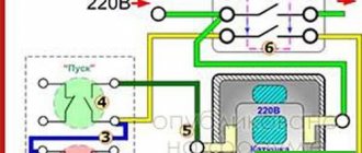
Connecting starters
The process of connecting the PML starter includes attaching the operating and supply circuit wires to the power contacts, connecting the power to the control coil.
Coil connection
To connect the control coil, wires from the button are connected to its two terminals. The wires used are the same as for installing the operating load circuit.
Additional devices
Additional devices used in conjunction with electromagnetic contactors of the PML series include the following:
- Thermal relays – protect the load connected to the contactor from high currents;
- Buttons – used to turn on the contactor;
- Contact extension attachments – used to increase the number of contacts in the operating circuit;
- Time delay relay – allows you to set the delay time for the contacts to operate.
When working with this type of electrical switching devices, experts advise not to disassemble and repair them yourself without special skills and experience. Technical inspection, disassembly and repair of starters should only be performed by qualified electricians.
Design
Magnetic starter PM12
Structurally, the electromagnetic contactor consists of two main blocks:
- Bottom (base) - this block consists of a cover, inside of which there is an W-shaped fixed magnetic circuit with a control coil in the central part. The number of turns and dimensions of the control coil depend on the voltage applied to it. Thus, in Soviet and modern models of these devices, coils designed for voltages from 24 to 380 V can be installed.
- Upper (contact group) - this block includes two types of contacts: movable and fixed. Spring-loaded movable contacts are located on a traverse with a fixed magnetic circuit (core) having the same shape and dimensions as that installed in the base. In this case, the cores of the base and contact group, identical in shape and size, are located opposite each other.
Two groups of fixed contacts are located on both sides of the movable traverse and secured in special grooves with screws. One group of such contacts is supplied with power cables that are under the voltage required to power the load. The second group of contacts is connected to the operating circuit - the cables that power the load.
Since sparking often occurs when connecting relay contacts, the entire upper part of the device is covered with a special cover that acts as a spark arrester.
PML contactor design
Between the upper and lower blocks there is a return coil or leaf spring.
On a note. For safety and more convenient control of the device, it is often placed in a sealed case with two buttons: “Start” and “Stop”. Some models often have a third button – “Reverse”.
Installation drawings (diagrams) and contactors
The wiring diagram shows all types of connections, connections and arrangement of elements. It is used during the period of direct electrical installation work. Such diagrams belong to the category of working drawings used during installation and connection of installations and equipment. They are also used to assemble some types of electrical structures and devices - switchboards, cabinets, control panels, etc.
This type of drawings includes graphics relating to all cabling and wiring connections between machines, starters and other devices. The connection of electrical panels and cabinets with other electrical equipment is also displayed here. In order to correctly connect the conductor lines, images of electrical terminal blocks, instrument terminals and devices are applied to the wiring diagram. Wires and cables are marked with their cross-section, and individual conductor lines are numbered and marked with letter symbols.
Contactors on wiring diagrams, depending on the series and model, are designated as KN, KV or KM. The first symbol indicates the series, and the second and third symbols indicate the type of contactor - vacuum and magnetic. A more detailed diagram shows the coil and its magnetic core, the connecting link between the core and the power contacts. If necessary, the device body is indicated in the form of an outline. When connecting devices three-phase, the general principle remains unchanged, with the exception of additional power contacts.
Sometimes a contactor and its designation on single-line diagrams can be accidentally confused with a magnetic starter. To avoid such mistakes, the following factors must be taken into account:
- For contactors, the contact designation is done in the shape of a semicircle or without any additional graphic symbols at all. Magnetic starters or trip units use a block contact to indicate the mechanical connection, corresponding to the circuit breaker lever.
- There is a difference in the designations of the housings of both devices. For the contactor, the housing is drawn in dotted lines with the obligatory image of the electromagnet and the power contacts associated with it. In most cases, with magnetic starters the housing is not displayed at all.