Reversing an engine is a change in rotor rotation to the opposite direction. You can change the direction of rotation for a DC electric motor, an asynchronous and commutator AC motor. It is difficult to imagine a device that does not use reverse rotation of the electric motor. Without a change in rotation, it is impossible to imagine the operation of a hoist, beam crane, winches, lifting mechanisms, elevators, valves, etc. The exception is devices such as sharpening machines, hoods, etc. In this article we will tell readers of the Sam Electric website how to reverse electric motors of different types.
Reversing DC motors
The easiest way to reverse a DC motor is that it has a permanent magnet stator. It is enough to change the polarity of the power supply so that the rotor begins to rotate in the opposite direction.
It is more difficult to reverse a motor with electromagnetic excitation (series, parallel). If you simply change the polarity of the supply voltage, the direction of rotation of the rotor will not change. To change the direction of rotation, it is enough to change the polarity only in the field winding or only on the rotor brushes.
To reverse high-power motors, the polarity should be changed at the armature. A break in the field winding while the motor is running can lead to a malfunction, because the resulting EMF has an increased voltage, which can damage the insulation of the windings. Which will lead to failure of the electric motor.
To reverse the direction of rotation of the rotor, bridge circuits using relays, contactors or transistors are used. In the latter case, you can also regulate the rotation speed.
The figure shows a circuit using transistors. To illustrate the operation, the transistors are replaced by switch contacts. Similarly, bridge circuits are made not on bipolar, but on field-effect transistors.
The efficiency of such a circuit is much higher than that of transistors. Control is carried out by a microcontroller or simple logic circuits that prevent simultaneous signaling.
Formulation of the problem
Let's assume that an asynchronous single-phase motor, already connected using a starting-charging capacity, initially has a shaft rotation directed clockwise, as in the picture below.
Let's clarify the important points:
- Point A marks the beginning of the starting winding, and point B marks its end. A brown wire is connected to the starting terminal A, and a green wire is connected to the ending terminal.
- Point C marks the beginning of the working winding, and point D marks its end. A red wire is connected to the initial contact, and a blue wire is connected to the final contact.
- The direction of rotation of the rotor is indicated by arrows.
We set ourselves the task of reversing a single-phase motor without opening its housing so that the rotor begins to rotate in the other direction (in this example, against the movement of the clock hand). It can be solved in three ways. Let's take a closer look at them.
Changing the direction of rotation of the rotor of an asynchronous motor
The most widespread in industry are asynchronous motors powered by a three-phase voltage of 380 volts. In order to reverse, it is enough to change any two phases.
A connection diagram based on two magnetic starters has become widespread. Actually for DC motors it is similar, but two-pole contactors or starters are used. This circuit is called “reversible starter circuit” or “reversible circuit for starting an asynchronous three-phase electric motor.”
When you turn on the KM1 starter with the “Start 1” button, voltage is directly supplied to the windings and the “Start 2” button is blocked from accidental activation by opening the normally closed contacts of KM-1. The motor rotates in one direction.
After turning off the KM1 starter with the “Stop” button or completely removing the voltage, you can turn on the KM2 with the “Start 2” button. As a result, line L2 is supplied directly through the contacts, and L1 and L3 are swapped. The “Start 1” button is blocked, since the normally closed contacts of the KM2 starter are driven and opened. The engine begins to rotate in the other direction.
The circuit is used everywhere to this day for connecting a three-phase motor in a three-phase network. The simplicity of the circuit design and the availability of components are its significant advantages.
Electronic control systems are the most widespread. Switching circuits, which are assembled on thyristors without starters. Although starters can be installed to remotely turn on or off in this circuit.
They are more complex, but also more reliable than contactor-based devices. For control, pulse-phase control systems (PFC) and frequency control systems are used. These are multifunctional devices, with their help you can not only reverse an asynchronous electric motor, but also regulate the rotation speed.
At home, it becomes necessary to connect a 380V to 220V motor with reverse. To do this, it is necessary to switch the star-delta windings. We looked at the differences between these schemes in more detail in an article posted on the site earlier:.
However, if a three-phase electric motor is supposed to be connected to a single-phase network, then a capacitor is used for this, which is connected according to the diagram below.
In this case, in order to reverse, it is enough to switch the network wire from B to terminal A, and disconnect the capacitor from A and connect to terminal B. It is convenient to do this using a 6-pin toggle switch. This is a typical connection of an asynchronous electric motor to a 220V network with a capacitor.
Option 3: changing the starting winding to the working winding, and vice versa
It is possible to organize the reverse of a single-phase 220V motor using the methods described above only if taps from both windings with all beginnings and ends come out of the housing: A, B, C and D. But there are often motors in which the manufacturer intentionally left them outside only 3 contacts. In this way, he protected the device from various “homemade products”. But still there is a way out.
The figure above shows a diagram of such a “problematic” motor. It only has three wires coming out of the housing. They are marked with brown, blue and purple colors. The green and red lines corresponding to the end B of the starting winding and the beginning C of the working winding are interconnected internally. We will not be able to access them without disassembling the engine. Therefore, it is not possible to change the rotor rotation using one of the first two options.
In this case, do this:
- Remove the capacitor from the initial terminal A;
- Connect it to the final terminal D;
- From wires A and D, as well as the phase, taps are made (you can reverse it using a key).
Look at the picture above. Now, if you connect the phase to tap D, the rotor rotates in one direction. If the phase wire is transferred to branch A, then the direction of rotation can be changed in the opposite direction. Reversing can be done by manually disconnecting and connecting the wires. Using a key will help make the job easier.
- The length of the starting and working windings is the same;
- Their cross-sectional area corresponds to each other;
- These wires are made of the same material.
All these quantities affect resistance. It must be constant at the windings. If suddenly the length or thickness of the wires differ from each other, then after you organize the reverse, it turns out that the resistance of the working winding will become the same as it was before for the starting winding, and vice versa. This may also cause the engine to fail to start.
It is easy to reverse a 220V asynchronous motor if the ends of the windings are diverted from the housing to the outside. It is more difficult to organize it when there are only three conclusions. The third reversing method we considered is suitable only for short-term connection of the motor to the network. If work with reverse rotation promises to be long, then we recommend opening the switching box using the methods described in options 1 and 2: this is safe for the unit and efficiency is maintained.
Connection diagram for a commutator motor with reverse
To reverse a commutator motor, you need to know:
- Not every commutator motor can be reversed. If a rotation arrow is indicated on the housing, then it cannot be used in reversible devices.
- All high speed engines are designed to rotate in one direction. For example, in an electric motor installed in angle grinders.
- For an engine that has low speeds, rotation can occur in different directions. Such motors are mounted in power tools, for example, electric drills, screwdrivers, washing machines, etc.
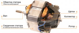
The figure shows a diagram of a universal commutator motor, which can operate on both direct and alternating current.
To change the rotation of the rotor, it is enough to change the polarity of the voltage on the rotor or stator winding, as in DC motors, from which universal machines are practically no different.
If you simply change the polarity of the supply voltage to the commutator motor, the direction of rotation of the rotor will not change. This must be taken into account when connecting the electric motor to the network.
You should also know that in high-power motors the armature winding is switched. When switching the stator windings, a self-induction voltage arises, which reaches values that can damage the motor.
Amateur designers use various types of engines in their crafts. They often use a brush motor from an automatic washing machine. These are convenient motors that can be connected directly to a 220 volt network. They do not require additional capacitors, and the speed can be easily adjusted using a standard dimmer. Six or seven pins are output to the terminal block.
Depends on engine type:
- Two go to the commutator brushes.
- A pair of wires come from the tachometer to the block.
- The field windings may have two or three wires. The third is used to change the rotation speed.
To reverse the motor from a washing machine, you should swap the leads of the field winding. If there is a third output, then it is not used.
Required Components
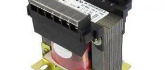
Independently connecting the motor for reverse rotation will not cause any particular difficulties if you follow the diagram provided. One of the important components that will facilitate this task is a magnetic starter or contactor. In fact, a magnetic starter and a contactor are not identical concepts. To put it simply, the contactor is part of the magnetic starter, but for simplicity, in the article both concepts are used as equivalent. Magnetic starters are precisely used for starting, reversing and stopping asynchronous motors.
Perhaps the question arises as to why you can’t use a regular switch or power circuit breaker. In principle, this is acceptable, but the starting currents that the engine needs for normal operation are not always safe for humans. When switched on, a breakdown may occur, which will damage both the switch and harm the operator. To minimize risks, you will need a starter. In it, the contact part is separated from the one with which the operator interacts. It contains a separate module with a coil that creates an electromagnetic field. The coil may require 12 volts or more to operate. When this voltage is applied, it interacts with the metal core, which is pulled into the coil. A plate is attached to the core, which goes to the contact group. They close and the engine starts. Stopping occurs in reverse order.
In addition to the contactor, you will need a three-button station. One key performs the stop function, and the other two start functions with a difference in the direction of rotation. A three-button station must have two normally open contacts and one normally closed. Simply put, the normal position of the contactor is its non-operating position. That is, when a contact is acted upon, it either closes or opens. If in operating condition it is closed, it is designated as NO, and if it is open, it is designated as NC. The NC contact is used for the stop button.
Asynchronous or collector: how to distinguish
In general, you can distinguish the type of engine by a plate - a nameplate - on which its data and type are written. But this is only if it has not been repaired. After all, anything can be under the casing. So if you are not sure, it is better to determine the type yourself.
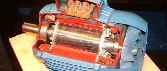
This is what a new single-phase capacitor motor looks like
How do collector motors work?
You can distinguish between asynchronous and commutator motors by their structure. The collectors must have brushes. They are located near the collector. Another mandatory attribute of this type of engine is the presence of a copper drum, divided into sections.
Such motors are produced only as single-phase ones; they are often installed in household appliances, as they allow one to obtain a large number of revolutions at the start and after acceleration. They are also convenient because they easily allow you to change the direction of rotation - you just need to change the polarity. It is also easy to organize a change in the rotation speed by changing the amplitude of the supply voltage or its cutoff angle. That is why such engines are used in most household and construction equipment.
Commutator motor structure
The disadvantages of commutator motors are high operating noise at high speeds. Remember a drill, an angle grinder, a vacuum cleaner, a washing machine, etc. The noise during their operation is decent. At low speeds, commutator motors are not so noisy (washing machine), but not all tools operate in this mode.
The second unpleasant point is that the presence of brushes and constant friction leads to the need for regular maintenance. If the current collector is not cleaned, contamination with graphite (from brushes being worn out) can cause adjacent sections in the drum to become connected and the motor simply stops working.
Asynchronous
An asynchronous motor has a stator and a rotor, and can be single or three-phase. In this article we consider connecting single-phase motors, so we will only talk about them.
Asynchronous motors are characterized by a low noise level during operation, therefore they are installed in equipment whose operating noise is critical. These are air conditioners, split systems, refrigerators.
Structure of an asynchronous motor
There are two types of single-phase asynchronous motors - bifilar (with a starting winding) and capacitor. The whole difference is that in bifilar single-phase motors the starting winding works only until the motor accelerates. Afterwards it is turned off by a special device - a centrifugal switch or a start-up relay (in refrigerators). This is necessary, since after overclocking it only reduces efficiency.
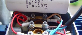
In capacitor single-phase motors, the capacitor winding runs all the time. Two windings - main and auxiliary - are shifted relative to each other by 90°. Thanks to this, you can change the direction of rotation. The capacitor on such engines is usually attached to the housing and is easy to identify by this feature.
You can more accurately determine the bifilar or capacitor motor in front of you by measuring the winding resistance. If the resistance of the auxiliary winding is twice as large (the difference can be even greater), most likely this is a bifilar motor and this auxiliary winding is a starting winding, which means that a switch or starting relay must be present in the circuit. In capacitor motors, both windings are constantly in operation and connecting a single-phase motor is possible through a regular button, toggle switch, or automatic machine.