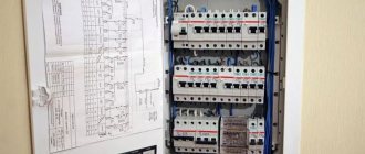
Apartment electrical panel diagram - single-phase version
Before physically installing a switchboard in your apartment, you need to accurately determine on paper the electrical panel diagram.
What modular equipment should I install, how many and what rating will the circuit breakers be, should I install differential circuit breakers and RCDs? What price will this or that equipment cost? Most of these questions, along with the diagrams themselves, will be displayed in the article. It is worth noting that all the diagrams below are intended specifically for single-phase apartment panels directly located in your apartment. It is assumed that the metering panel with a meter and an input machine is already installed in the floor panel. Accordingly, its image is not present on the diagrams.
Conclusions based on the results of the work done
Now it makes no sense to talk about the amount of my financial expenses. Any costs always depend on the quality of the product, the manufacturer of the automatic protection elements and other parts required for assembly. I can only say one thing: the savings on specialist labor costs amounted to about 10,000 rubles. The whole job (I had no such experience) took a total of about 5 hours. Again, the amount saved can be many times greater. It largely depends on the region, average prices and salaries in the city. However, even saving a small amount is worth doing all the work yourself. And experience will never be superfluous.
I really hope that the description of my work will be useful to you. If something is unclear, write in the comments. I visit Homius.ru often, and if I missed anything, I’ll be sure to add it. Good luck everyone!
The editors of Homius.ru invite home craftsmen and craftsmen to become co-authors of the “Stories” section. Useful first-person stories will not only be published on the pages of our online magazine, its authors will receive a small financial reward.
Subscribe to our channel in Yandex.Zen so you don't miss anything! Did you like the article? Save so you don't lose!
Regulatory documents and rules for shields
All diagrams and apartment panels must be assembled in accordance with regulatory documents and not contradict the instructions and rules prescribed there. First of all, this is, of course, the PUE, but there are two more documents that are worth paying close attention to:
Requirements from the rules for apartment panels
Notes and requirements from the above GOST that you should pay attention to when assembling and choosing an apartment panel:
Sixth stage of work: installation of the zero bar
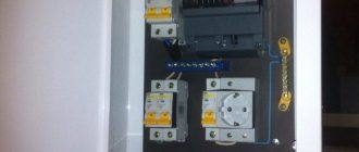
Modern boxes are designed in such a way that the zero bus, like the ground bus, is hidden by a plastic casing. Essentially, these are terminal blocks for a certain number of contacts, which are fixed on a plastic base. This is much more convenient than using a conventional bus, because in our case, RCDs are used, the neutral wires of which should not be connected. Otherwise, the device will constantly trip for no reason at all.
It was decided to leave connecting the residual current circuit breaker “for later”, fortunately it will be quite easy to do. But I installed all three RCDs at once, allocating a separate zero strip for each of them. A huge advantage of such buses is that they do not require pulling contacts. You just need to stick the bare wire into the hole, where it is automatically fixed. The downside is that a flexible wire, the end of which is not crimped with a ferrule, cannot be fixed in the bar.
A plastic base is installed at the bottom of the box, onto which the zero bars are attached
Simplified diagram of an apartment panel
This scheme is suitable for small one or two room apartments. Where the total length of all wires and cables does not exceed 300-400m.
There is a load switch at the input, not a circuit breaker. If you already have protection installed on the floor switchboard, after or before the meter ( check this before assembling this circuit ), then it is not necessary to install a machine at the input. The better the load switch from the machine can be found in the article Modular load switch or incoming machine.
The rated current of the input device for apartments with electric stoves and single-phase load should be from 40A and above.
Below are group cables feeding certain groups, indicating the cable brand and its cross-section depending on the load. Outgoing lighting circuits made with a 1.5mm2 cable are protected by a 10A circuit breaker, socket groups with a cross section of 2.5mm2 are protected by 16A.
The bathroom is connected to the differential machine, i.e. sockets, lighting and all consumers in the bathroom are combined into one group. Moreover, the leakage current on the diff is selected to be 10 mA.
Some electricians set it to 30mA, citing possible false alarms. There is no specific prohibition in the rules; it stipulates that this protection should not exceed 30 mA . Why it is still better to set it to 10mA can be understood by familiarizing yourself with how a current of a certain magnitude affects your body:
True, in order to purchase 10mA differential automatics in stores, you will most likely have to place an order. Basically, devices with a leakage current of 30 mA predominate on the free market.
The hob and oven are powered in separate groups, implying that these are two different consumers. If you have an electric stove, that is, when the hob and oven are combined, you need to change the power cable and circuit breaker:
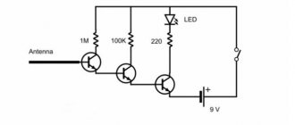
If you are concerned about power outages and want to protect your equipment from power surges, then you can slightly increase the cost of the circuit by adding a voltage relay to the input. Here is a schematic representation of a relay of the UZM-51M brand, as the easiest to connect (input-phase + zero and output-phase + zero).
The big disadvantage of the circuit is that if there is a current leak in lines other than the bathroom, the protection will not work.
This circuit can be improved by placing an RCD at the input. Before doing this, make sure that a circuit breaker is installed in the floor panel where your meter is located, since it is prohibited to install an RCD without a circuit breaker. If there is already an RCD or automatic circuit breaker there, then it makes no sense to duplicate the protection. The circuit with the RCD at the input will be like this:
One caveat - if your total cable consumption in the wiring of an apartment is 400 m or more, then false alarms of the input RCD are possible due to total current leaks. Here it is already advisable to apply the RCD to separate groups, removing the introductory one from the apartment panel diagram.
First stage: placing the automation on the top rail
For convenience, you should first arrange the elements. On the top rail were placed (from right to left):
- input two-pole circuit breaker 63 A;
- multifunctional protective device (UZM);
- three RCDs for groups: lighting, hob and oven, other sockets in the house;
- automatic residual current switch (RCCB), through which the washing machine will be powered.
Note! There is no electric meter in the box. This was done because the distribution panel, which is located in the apartment, was being assembled. The electric meter remained where it was - in the input panel on the staircase.
Top row of protective automation in a plastic box
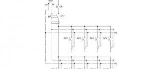
Electrical panel diagram in an apartment with an RCD in separate groups
This scheme is already more advanced. It can be used both in small apartments and in apartments with a total wiring length exceeding 400m. There is no input RCD here, since a load switch is sufficient (do not forget about the circuit breaker in the floor panel with a meter).
The rated current of the input device was selected based on the permitted power for apartments with a single-phase load equal to 11 kW and the demand factor for luxury apartments - 0.8.
There is protection against current leakage on individual groups of sockets and split systems (air conditioners). Moreover, one RCD protective device is located on combined groups, each of which in turn is protected from overloads by automatic circuit breakers.
Preparatory activities
Selecting the main parameters of the electrical network of your apartment
- The choice of cross-section and material from which the electrical wiring in a one-room apartment will be made, and its layout largely depend on the type of installation and the total power of all connected devices. Therefore, first of all, we should draw up a plan for the location of sockets and the lighting network. In this case, you should be guided by the norms of the “Rules for the Construction of Electrical Installations” (PUE) and basic concepts of convenience.
- Installation of switches in the bathroom is prohibited
- It is prohibited to install sockets without RCD circuit breakers in the bathroom.
- Switches in rooms should be located near the door on the door handle side.
- Sockets in residential premises can be located based on their ease of use. In this case, the recommended values are a height of 0.3 to 1.8 meters.
- Switches are usually located at a height of 0.6 - 0.8 m.
- The next important step is choosing a wiring diagram. The method of open wiring in boxes or hidden wiring in walls can be used. Each of these methods has its own advantages and disadvantages. So the advantages of open wiring include:
- Possibility of installation without making repairs to the room. You simply install an additional box under the ceiling, into which the wiring is subsequently laid.
- Installation time is significantly reduced. So, with the right approach, all the wiring in a one-room apartment can be replaced literally in one day.
- Ease of carrying out repair work and subsequent installation of additional electrical receivers.
- But hidden wiring has several more advantages:
- According to the PUE, significantly lower requirements are imposed on hidden wiring. As a result, it is not always necessary to use additional protection against mechanical and thermal damage. And there is no need to buy additional boxes for it. Thanks to this, the issue price is significantly lower.
- Hidden wiring with the same wire cross-section has slightly higher tolerances for nominally permissible currents and overload currents. This is achieved due to better heat transfer performance.
- Hidden wiring does not spoil the appearance of your apartment at all and does not take up the already small space of the apartment.
- Based on all this, we can conclude that open wiring is chosen only in exceptional cases. For example, when the repair has already been completed, but they forgot to replace the wiring. Or when wall gating is extremely undesirable due to the dilapidation of the building. In other cases, the best option is, although more labor-intensive, the option of hidden wiring.
Calculation of the electrical network of a one-room apartment
First of all, we need to calculate the rated load of all your electrical receivers. To do this, we use a simplified formula; where P is the rated power of electrical appliances, U is the rated voltage of the electrical network (for a single-phase network it is 220V), and I is the rated current of our electrical network.
- Based on this formula, an electrical appliance with a power of 1 kW consumes a current of 4.55 A. To simplify the calculation and create a certain reserve, we take it equal to 5A.
- When calculating your electrical network, take into account only realistically possible situations of its use with maximum load. You should not rely on the fact that you will connect four 2kW heaters in one room at once. After all, the probability of this is quite low. And the electrical wiring diagram in a one-room apartment will become significantly more complicated and will increase in price from such a calculation.
- Now let's start choosing the wire we need. This should be done in accordance with clause 1.3 of the PUE. But considering that our loads are not large and we do not need ultra-precise calculations, we make an approximate calculation. To do this, we assume that a cross-section of 1 mm2 copper wire has a carrying capacity of 10A, and an aluminum wire has a carrying capacity of 5A.
The next defining point for us in the PUE is clause 6.2.2. It states that group internal power supply networks must be equipped with circuit breakers with a rated current of no higher than 25A. Based on this, we should divide the loads in the apartment in such a way as to divide them into groups of no more than 25A each.
Price for complete set of apartment panels
Prices only for component modular equipment (automatic circuit breakers, RCDs, voltage relays, load switches) from different manufacturers for assembling all the above circuits are summarized in one table. Prices are taken from online stores and may vary significantly in your region.
| Scheme name | Manufacturer and price | ||||
| IEK | ABB | Legrand | Schneider | KEAZ | |
| Scheme No. 1 | 1700rub | 6700rub | 7300rub | 4300rub | 2100rub |
| Scheme No. 2 | 1600rub | 6600rub | 7200rub | 4200rub | 2000rub |
| Scheme No. 3 | 4200rub | 9200rub | 9800rub | 6800rub | 4600rub |
| Scheme No. 4 | 2400rub | 6900rub | 8100rub | 5100rub | 2700rub |
| Scheme No. 5 | 3400rub | 9700rub | 10300rub | 7500rub | 3700rub |
| Scheme No. 6 | 5900rub | 12200rub | 12800rub | 10000r | 6200rub |
All of the above diagrams are just one of many options for laying out an electrical panel in an apartment. The purpose of the article was to show their display in graphical form and make an approximate comparison of the monetary costs of modular equipment in one design or another. In each individual case, everything must be calculated according to the loads, the amount of equipment, the physical space in the switchboard and your financial capabilities.
Source
Assembling an electrical panel for a one-room apartment
Assembling the switchboard is not particularly difficult. Almost anyone can do this on their own if they have the desire to do it, know how to think and want to work with their hands. In continuation of a series of articles about organizing electrical wiring in a one-room apartment, I am publishing material with visual step-by-step photographs of assembling a simple switchboard. Here you will learn how to assemble a panel for an apartment with protection against overload, short-circuit currents and protection against accidental human contact with live parts. For this purpose, circuit breakers and RCDs will be used. I will tell you how to do all this without using additional special electrician tools, such as crimping pliers, etc. So, let's move on to the assembly.
Here is the built-in cabinet itself for 18 modules of the Easy9 Box series from Schneider Electric.
In it we will install an introductory 2-pole circuit breaker, two RCDs and seven group circuit breakers.
I always do it this way. I install the introductory machine on the left, and then on the right I add other devices in turn. This is very convenient in understanding the diagram. First the input, then two group RCDs and at the end all the machines.
All modular devices are mounted on a standard DIN rail, which usually comes with the housing.
We planned to protect three lines with the first RCD, i.e. connect three circuit breakers to it. The second RCD is the remaining four lines. To do this, we take a single-phase comb busbar and cut it into the required sections. In our case, you can see the photo below. I would like to note that before sawing it is worth removing the dielectric protection (plastic casing) from the busbar.
Then we insert the combs into the machines and apply the tire body to them to determine its length. You can clearly see it in the photo below. You can cut off the tire body with a margin of 3-5 mm on both edges. Then you can do without side plugs.
It should turn out something like this.
Now we insert two small combs into the dielectric housing. If they are installed in place in the machines, then both cut tires will not contact each other. A distance between them of almost one centimeter is quite enough.
It should look like the photo below. Here one comb combines three circuit breakers, and the second connects the remaining four. Due to the solid dielectric housing, this is not visible, but everything is neatly closed.
Now we need to make jumpers from the input machine to the RCD. This is to supply “phase” and “zero” to the corresponding upper contacts of the protective devices. For these jumpers, you can buy 1 meter of VVNng 2x6 cable and cut it. The wires in it are round and rigid and therefore do not need to be crimped with tips. If you take a soft wire, for example PV3, then it will need to be crimped with pin lugs. To do this, you will have to buy special press pliers (crimpers). This is an additional expense of approximately one thousand rubles. Moreover, if you are not an electrician, you will no longer need them.
Below in the photo is an example of a phase jumper. Your curves may be different.
Let's put it in its place. This is to connect one lower contact of the input 2-pole circuit breaker with the upper phase contact of the first RCD. From the front it will look like the photo below.
And so on the other side.
We make a zero jumper in the same way. In this option there will be no input common zero bus, because zero can be applied to both RCDs at once.
Using a zero jumper, we connect the other lower contact of the input circuit breaker with the upper zero contact of the first RCD. This is what it will look like from the front.
At the next stage, we supply the phases from the RCD to the group circuit breakers. To do this, we again make two jumpers from a rigid cable.
Our first RCD will protect the first three group circuit breakers. Therefore, from the lower phase contact of the RCD we connect a jumper to the upper contact of the first group circuit breaker, which in turn is connected by a comb to two adjacent circuit breakers. Thus, with one jumper we transfer the phase to all three machines.
From the reverse side it will look like this.
We connect the second jumper to the lower phase contact of the second RCD and to the second group of four circuit breakers. This can be seen in the photo below.
Below you can see how the wires are inserted into the machines together with the combs.
In the shield body it looks like this.
Since we have two RCDs, this means we need to install two instead of one zero bus. I described in detail how to do this here.
Now we make zero jumpers.
With one zero jumper we connect the lower zero contact of the first RCD with the first zero bus. The neutral conductors of all group lines protected by the first three group circuit breakers will be connected to this bus, i.e. which are connected to this RCD. Similarly, we connect the second zero jumper for the second RCD.
In principle, the assembly of the distribution board for a one-room apartment is complete. All that remains is to put the top cover in place and take the shield to the site.
“I have a very tense relationship with electricity. I'm afraid of him. And it just hates me. He hits at every opportunity.
Source
How to properly connect machines and RCDs
Before starting work on connecting the machines, it is necessary to prepare all the devices:
- Mounting rail (sometimes it is already included with the finished shield). In other cases, you will need to measure the required length yourself and cut it with metal scissors.
- Screwdriver.
- Wire cutters.
- Wire stripper.
Connecting machines and RCDs - step-by-step instructions
Step 1. To begin, you should attach two buses to a metal DIN rail: neutral and ground. This is easy to do; you just need to insert them at one end and then snap them into place.
This is what the tires should look like after installation.
Step 2. Now you need to secure the machines in series. At the bottom they have a special latch, which you just need to pull down and then secure the machine to the rail.
Each machine must be secured to the rail one by one.
Step 3. Next you need to take a three-core cable. As a rule, the ground wire is yellow, the neutral is blue, and the phase is white or pink (as in our case).
It is important not to mix up the power cable wires
Step 4. First we need to connect the neutral wire to the neutral bus. This is easy to do - you just need to unscrew the bolt with a screwdriver.
There is a hole for cables of different sections
Step 5. Now you need to connect the yellow ground wire to the ground bus.
This is done in the same way as in the previous version.
Step 6. The next step is to secure the power wire (pink). Contrary to many opinions, it should always come from the top. You should connect the wire, but you shouldn’t tighten it right away - the reason is that you will then have to supply the power wire to all other machines.
In this step, the wiring is connected “live”
Step 7. Seventh: you need to insert the power wire into the upper machine, and then insert one end of the additional jumper into the same hole.
Now you need to insert the jumper into the adjacent machine, and then into the other, alternately tightening the screws
Step 8
Now you need to pay attention to the last differential machine. On its body, as a rule, there is a connection diagram
The first input here will be designated by the letter N - this will be zero, the second input will be designated as I (L) - this will be the phase.
Step 9. Now it has become clear that the phase is at the second input, which means that the other end of the yellow jumper wire should be secured there. We tighten the screw by analogy with the previous options.
Thus, we have completed connecting the power cable that comes from the shield
Step 10. Now you need to connect the wires that come from the room. First, you will need to remove the insulation layer from their ends. A special tool is used to strip the ends of the wires.
Here you can turn the screw and set the wire thickness
Step 11. Here you should also connect the neutral wire to the corresponding bus.
You can unscrew any loose bolt
Step 12: Now you need to secure the ground wire again.
The wire must be tightened carefully, without catching the insulation layer.
Step 13. Now from below we fix the power wire that comes from the electrical device.
The following wiring, by the same analogy, will be connected only from below
Step 14. Now you need to take an additional wire, connect it to the zero bus, and then to the first input on the differential machine.
We fix the wire in the first hole of the difavtomat
How to assemble an electrical distribution panel for an apartment
The process of assembling a switchboard requires special skills and knowledge. The service life of the devices and the reliability of the home’s power supply system depend on the correctness of the chosen scheme and the distribution of consumers. If in old houses with a minimum number of electrical appliances two or three automatic machines were enough, then in modern housing it is necessary to take care of the reliability of the network. Below are basic recommendations on how to assemble a switchboard for an apartment, what circuits and devices should be used, as well as recommendations for eliminating errors.
Preparation: what you will need for work
The main thing is that all the necessary equipment is at hand. During the assembly process, it is quite inconvenient to run to the pantry for one device or another. Main tools used in work:
- Phillips and slotted screwdriver;
- side cutters, pliers;
- scissors and hacksaw for metal;
- stripper (tool for removing insulation). It can be replaced with a simple stationery knife;
- cable with a cross section of 6 mm2 and 4 mm2;
- a piece of wire with a plug for testing;
- multimeter (useful for finding wiring errors).
What is an electrical panel and what is it for?
An electrical panel is a structure consisting of complex modular devices designed to control the power supply network. The main purposes include:
As a rule, they are mounted together with an electricity meter for greater convenience. In new housing stock, where metering devices are located in the corridor, shields are installed at the front door.
Important! It is necessary to provide free access to the panel in order to turn off the machines if necessary.
Principles of distribution of electricity by groups
Distribution boards, in which several machines are used for the entire apartment, are a thing of the past. The need for a large number of modular devices is explained by convenience and increased safety. If an outlet breaks down in one of the rooms, you can turn off one circuit breaker, and the rest of the network will continue to operate as normal. The basic rules for assigning groups are described below.
Reference! The rating of the machine directly depends on the cross-section of the cable, as well as the power of the consumers.
Next step: move on to the automation of the bottom row
First of all, we move all the machines to the right all the way, placing them under the central control unit and the automatic machine. We fix them in this position using a limiter. By the way, this is a rather convenient device, especially if the modular plugs in the decorative cover of the box are broken. In this case, such a limiter will not allow the machines to move along the DIN rail.
The input contacts of the lower row are also bridged with each other using a copper busbar with plastic insulation, similar to the automation of the upper row. And here I approached the matter a little unconventionally. Despite the fact that the tire itself is divided into segments according to groups of machines, the plastic body remains solid.
The lock will help secure the machines to the DIN rail so that they do not move
Drawing up a diagram
Modern power supply systems involve the use of a three-wire cable, where one wire is a phase, and the rest are ground and zero. Given the growing power of devices, it is also necessary to divide them into groups, which allows to increase the service life of the wiring. Guided by these principles, we proceed to drawing up a diagram of the shield.
Advice! It is better to entrust the design of the panel and electrical wiring of the apartment to a professional so as not to miss important details. Otherwise, you will have to redo the repair.
It is mandatory to install a protection device on the input cable, which will protect the internal network from overvoltage. Then they install a voltage relay to control surges in the network, after which they proceed to the installation of groups and individual lines. It is worth noting that for powerful devices, in addition to switches, additional RCDs or differential circuit breakers are used. Such organization of the home electrical network is not only safe, but also convenient. If necessary, you can turn off the machine and turn off the washing machine. You can also turn off the RCD and de-energize all consumers included in the global group.
An additional tool to help you make quality contacts
To ensure that everything was done neatly and that the electrical contacts did not get hot during operation, I used a cable crimping kit. It can be purchased at any hardware store. It cost me one and a half thousand rubles, including a crimper (crimping tool), but if you look, you can find it cheaper. There are quite a lot of tips in the set, so if you use it only for personal purposes, it will last for more than one decade.
Crimping lugs are very convenient for electrical installations
Electrical Panel Components
The distribution board consists of many devices. For reliable operation of the home electrical network and protection of household appliances, it is necessary to use circuit breakers, RCDs and differential circuit breakers, voltage control relays, buses and much more.
Circuit breakers
Devices for automatic protection of the line that is connected to them. They interrupt the power supply if the current in the line is significantly higher than the rated value. Protection against cable heating is also provided.
RCD and diffautomatic devices
The residual current device (RCD) switches off the load if leakage currents appear. First of all, people can suffer from them. The leak also negatively affects the wiring, causing the wires to heat up and catch fire.
Differential circuit breaker - protects against short circuits, overloads, and current leaks. It is often used instead of a combination of a pair of RCDs and a conventional machine. The main advantage is short circuit protection.
Voltage control relay
The device is used to measure the incoming voltage and maintain a given value. In case of sudden surges in the network, the device turns off the power supply. The electrical circuit is closed only after the indicator and time delay have been restored. The main purpose is to protect electrical appliances from power surges.
Grounding and grounding buses
Busbars for grounding and zero are used for ease of installation, as well as compliance of the shield with all the rules of GOST and PUE. The number of DIN rails depends on the number of machines and other modules, so it is necessary to draw up an installation diagram in advance.
Comb tire
It is used instead of cable jumpers, which were previously made by electricians themselves. The comb looks like a solid plate with protruding teeth and is designed to connect machines standing in the same row.
Other equipment
As additional equipment in the distribution panel, modular contactors, load switches, DIN rail sockets, timers and much more are used. Other devices increase the convenience of managing the power supply network.
Stage No. 3: starting switching
Copper bus, which is located inside a plastic case
In order for everything to look neat, I decided not to use wire jumpers, but purchased special copper bars in plastic cases. In addition to aesthetics, installation with the help of such devices is greatly simplified. First you need to remove the plastic insulation, and then cut the tire to the required size.
To connect the RCD and RCBO to each other, you need 2 segments. One of them will go to zero contacts, the second to phase contacts. Both blanks are visible in the photo below. The plastic body can be cut to the same dimensions with a regular hacksaw.
The connecting busbar in the plastic insulator is installed in its proper place
When the elements of the connecting bus are cut to size, the plastic case is assembled, and the finished jumpers are mounted in the corresponding terminals of the protective automatic equipment. This installation allows you to subsequently not be afraid of electric shock when making revisions or removing dust, which will inevitably accumulate inside. The plastic insulator completely covers the live parts. You can verify this by looking at the photo.
How to calculate the number of places in an electrical panel?
All equipment for the switchboard is standardized and installed on a special DIN rail. The unit of measurement for space is considered to be a “module” with a width of 17.5 mm. All panels are sold depending on the amount of space: for 8, 12, 24, 36 modules.
Reference! To calculate the number of seats, it is necessary to take into account all devices, including RCDs, automatic machines, voltage relays, and differential automatic devices.
Circuit breakers have a standard width of 17.5 mm. The remaining devices have the following characteristics:
Selecting the shield body
As already described above, distribution boards come in surface-mounted and built-in types. If your wiring is hidden, then it is better to choose a structure recessed into the wall. The external shield can be mounted both inside the building and outside.
The issue of choosing the housing of such an electrical device is very important. First of all, you need to decide on its material. Plastic is not durable, but is lightweight, which makes installation easier. Metal stands out for its reliability and durability.
The optimal solution would be to purchase a case with removable walls - they facilitate the process of removing and moving DIN rails. As for the dimensions, it is advisable to have some reserve.
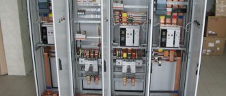
Electrical panel assembly
When the panel diagram has been created and the electrical wires have been laid around the apartment, we proceed to assembling the panel. If desired, you can order a prepared shield, which all that remains is to install and connect the input cable.
Advice ! Indoor renovation is a messy process, so it is recommended to assemble the panel in another place, and then install the finished equipment in place.
Marking and installing DIN rails
First, markings are made of where the modules will be located and how long the slats are needed. During the fitting process, they also take into account the distance between the rows, if there are several of them, as well as the distance between the zero and ground buses. When the marking is ready, the slats are installed in the required places.
Reference! Most panels are standardized, so the placement of the slats is limited by the manufacturers.
Installation and switching of modular devices
At the stage of installation of modular devices, automatic machines and additional devices are installed on a DIN rail. They are also connected to each other. First of all, they install an input circuit breaker, then voltage relays, RCDs and differential circuit breakers, which are located in front of conventional switches.
Advice! Install the modules closer to the center, leaving space on the sides for neat cable management.
Organization of cable entry into the electrical panel
At the stage of cable entry, it is necessary to make holes in the shield. As a rule, all insertion points are provided by the manufacturer, so it is enough to squeeze out the plastic. On one side, a general network cable is installed, which is connected to the input circuit breaker, and on the other, internal network wires.
Choosing an installation location
In most apartments, the shield is installed closer to the front door. This is not a mandatory requirement, the main thing is to follow a number of recommendations:
Cable cutting
Connecting consumer groups
During installation, modules are grouped depending on various factors. For example, by purpose or premises. Automatic devices for apartment lighting are installed one at a time, after which protective devices are installed for the kitchen, bathroom and other rooms.
Advice! Grouping consumers facilitates the process of operating the panel.
A few finishing touches
I am of the opinion that even if the master assembled the switchboard himself and remembers by heart which machine is responsible for which area, this information should be duplicated on the front panel. It’s not a fact that all malfunctions will occur only when I’m at home. It’s human nature to sometimes change jobs, go on business trips... but who knows? That's why I decided to computer print out the tags for the front panel. They were printed on plain paper and then simply taped together. They turned out like laminated ones. Now I am sure that any hired electrician can easily figure out which circuit breaker to turn off without removing the voltage from working sockets and lighting.
Now all that remains is to install the distribution panel in place, connect the wires going to the apartment to it, connect the power and enjoy the feeling of satisfaction from the work done.
Appearance of the distribution panel after completion of all work