A large amount of modern technological equipment is automated. These are pumping stations, boiler houses, power supply systems, and technological equipment. Process automation is often performed using microcontroller control circuits. But data collection for them is carried out by instruments and measuring sensors. Maintenance, repair, installation and adjustment of these devices is carried out by highly qualified specialists.
What are measuring instruments made of?
The measuring instruments consist of a primary measuring element and a transducer. A primary element is a device that converts a physical quantity into an electrical or non-electrical output signal. For example, thermocouples have an electrical output signal. For example, diaphragms, thermometers, and pressure gauges have a non-electrical output signal. Thermocouples produce a signal in millivolts. Diaphragms produce a signal in the form of a pressure difference before and after the diaphragm. But both of these elements are called primary converters. The non-electrical signal is then converted back into an electrical signal. For further signal processing and transmission over a distance.
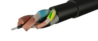
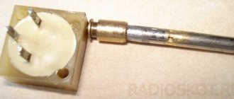
The primary transducer can be a thermocouple, a diaphragm, Bourdon tubes, various emitters with receivers of ultrasonic, optical, electromagnetic, and radiation signals. The primary element can be a metal plate that changes the oscillation frequency depending on the fluid flow rate. For an example, you can see the photo.
Flow meter emitter. The receiver looks similar
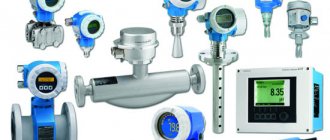
Flow meter, pressure and temperature sensors
Rotameter, pressure gauge, thermometer, dew point analyzer
Many different devices have been invented over many years of the existence of such a science as Control and Measuring Instruments (CIS). For each physical quantity, different types of transformations are used. All these transformations are based on knowledge of elementary physics. For example, the stronger the water flows in a pipe, the faster the turbine blades installed in the pipe will rotate. Another example is when two identical metal plates, when “glued” together, will bend. Because when heated or cooled, one will change its length more, the other less. We only need to convert these non-electrical parameters into any signal that we could see, in units of measurement that we understand. There are a lot of ways to do this. Each device manufacturer has its own developments for this. The generally accepted signals of primary elements are primary temperature transducers , these are thermocouples and thermal resistances. They will be described in more detail on a separate page. Basically, device manufacturers use their own designs and the signal from the primary converter is unknown to us.
Manufacturers can also use several different types of conversion in one measurement tool. For example, crude oil moisture meters. The primary converter uses both the capacitive measuring principle and the optical measuring principle.
Certificate data of the BOESN moisture meter indicating the calibration values of the capacitive channel and optical channel.
Other manufacturers produce measuring instruments with double conversion of environmental parameters into a primary signal. For example, Rosemount 3051 flow meters.
Rosemount 3051 Flowmeter
There is only one measuring device, and the conversion of the flow velocity of the measured medium into the pressure difference before and after the measuring element is used. This pressure difference is then converted into an electrical signal.
The secondary device converts the signal from the primary transducer into a standard electrical signal . In many cases, each measuring instrument that has a primary element has only its own secondary element. When working with such measuring instruments, it is always necessary to check the compliance of the primary and secondary elements with the passport for the measuring instruments. The secondary converter can also be in the form of a device combined with the controller. The controller can receive various signals from primary measuring elements, process their signals programmatically, and perform calculations of one parameter. For example, the amount of heat consumed.
Secondary devices of the thermal metering unit
Primary elements during their production may have slight deviations. These deviations are compensated for when setting up the secondary converter.
When working with devices that have a primary measuring element and a secondary transducer, it is imperative to read the safety precautions when working with the device. Many manufacturers do not allow the primary converter to be turned off without removing the voltage from the secondary unit. The device may malfunction .
Functions and tasks of instrumentation and automation specialists
The functions of the instrumentation and control department specialists are to ensure the operability and accuracy of the readings of all instrumentation and automated systems of the enterprise. The tasks of this department include monitoring the operation, adjustment and maintenance, repair and restoration of devices.
In the event of equipment failure, the Kipovets must react in a timely manner and replace the failed unit. The mechanic must conduct an inspection and, if possible, repair it within the department or at a specialized service organization. To do this, the instrumentation and control department must have spare parts, instruments and tools. Specialists of this department must conduct metrological supervision of measuring instruments to ensure the operation of all equipment. The instrumentation and control department belongs to the technical service of the enterprise and is functionally subordinate to the chief engineer.
What is the calibration interval?
Depending on the quality of the elements used, the type of materials, tests performed and operating conditions, manufacturers guarantee the preservation of device parameters for a certain period of time. This period of time is called the “intervalidation interval”. After this time has expired, it is necessary to check (verify) whether the measuring instrument corresponds to the parameters specified in the passport. The calibration interval is usually also indicated in the passport. For one device model, there may be a different calibration interval, depending on the year of manufacture.
When checking a measuring instrument, the magnitude of the change in the SI output signal at a certain measurement point is determined. For example 0; 25; 50; 75 and 100% of the measurement scale. Measurements are made both when the range increases from 0 to 100%, and when the range decreases from 100% to 0. All measured values are compared with the passport data. Deviations of measurement values from the passport data are called the error of the measuring instrument. Each device has its own tolerance. How to correctly carry out measurements is described in the Measurement Methodology (MI) for this measuring instrument. The magnitude of the permissible error is indicated in the passport for measuring instruments and in a document called “Type Description for the measuring instrument.”
What types of instrument errors are there?
4.1. Absolute error
Absolute error is the difference in readings between the measured value and the certified value. The absolute error is determined in the units in which the instrument readings are displayed. For example, for temperature transmitters this is degrees Celsius (Kelvin). The absolute error of an instrument may vary from one instrument to another. For example, in the range of 0-300 degrees there is one value. In the range of 300-1000 degrees there is a different value. An example of calculating the absolute error. At a set temperature of 200 degrees Celsius, the device shows 201 degrees Celsius. The difference between the true value and the measured value is 1 degree. This is an absolute error.
4.2. Relative error
Relative error - measured in %. To determine the relative error, it is necessary to determine the absolute error of the device. Then divide the resulting error by the number corresponding to the specified value of the medium being measured. The resulting value is multiplied by 100. The relative error is usually calculated for flow converters. For example, in a special testing device we set the flow rate to 200 cubic meters per hour. The device readings are 201 m3/h. The absolute error will be 1 m3/h. We divide the resulting value of 1 by the flow rate we set to 200. We get the number 0.005. All that remains is to multiply this value by 100%. We get the number 0.5%. This will be the relative error.
4.3. Reduced error
The given error is measured in the same way as the relative error in percent. In this case, this is the error of the device relative to the measurement scale. To calculate the reduced error, we first also determine the absolute error. Then we multiply the resulting value by the measurement limit. And to get % we multiply by 100. The given error is usually indicated for pressure gauges. Let's look at an example. The pressure gauge input has a measuring range of 0-200 kPa, and a testing device supplies 100 kPa. The reading on the pressure gauge corresponds to 102 kPa. The absolute error will be 2 kPa. Dividing 2 kPa by 200 kPa, we get a value of 0.01. Multiplying this value by 100% we get the reduced error of 1%.
4.4. Main error.
Main error. All three of these errors relate to the main error. Determination of relative, reduced and absolute errors is carried out in laboratory conditions, under environmental conditions that meet the requirements of the verification methodology.
4.5. Other types of errors.
Other types of errors. In addition to the main error in measurements, there are many more errors. I will not describe all types of errors. I’ll just list as an example what other types they are. This is additional, systematic, random, statistical, dynamic, instrumental, etc.
A measuring instrument whose characteristics during verification do not exceed the permissible values is considered suitable for further use. For measuring instruments whose error exceeds the permissible values, the primary or secondary converter is adjusted. The setting can be done either through software (by changing the coefficients) or mechanically. For example, by rotating variable potentiometers, changing the position of jumpers, or grinding the diaphragm. Sometimes, of course, we may not even suspect that at the moment some coefficients are changing. For example, when supplying test gas to a portable gas analyzer. The gas analyzer itself changes its settings programmatically. After automatic setup, the gas analyzer gives us a signal that the setup is complete and the date of the next verification.
Types of signals used in instrumentation.
Having familiarized ourselves a little with measuring instruments, we already understand that the readings of some measuring instruments can only be seen “in situ”. Only where they are mounted. These are, for example, thermometers (mercury, alcohol, bimetallic), pressure gauges, various flow meters, etc. But some measuring instruments generate their signal and transmit it via the measurement channel to the panel device or controller. In order to avoid different types of signals from different manufacturers, it was decided to use standard measuring signals.
Output signals are:
- 5.1 Pneumatic signals
- 5.2 Electrical signals
Responsibilities of a fitter
An instrumentation mechanic directly interacts with equipment and measuring instruments. The list of his responsibilities depends on his qualifications and rank. For example, a 6th category Kipovets has the knowledge and skills that allow him to service even spacecraft.
A mechanic of any qualification in production does a number of works, namely:
- repairs, adjusts and tests equipment;
- controls and ensures the performance of electrical measuring instruments;
- controls and checks the functioning of means of measuring physical quantities;
- makes arbitration measurements;
- monitors and promptly repairs the entire system;
- determines performance and wear;
- processes received signals and measurements.
If you decipher instrumentation and automation, it becomes clear that this is not just an intricate abbreviation - it provides various areas of life with convenience, comfort and safety.
High-quality functioning of any enterprise, plant or construction of a residential building is impossible without instrumentation and automation. Everything in human activity is associated with automation and convenience, so if any of this is eliminated, the quality of life will significantly suffer.
5.1. Pneumatic signals of measuring instruments with an output signal of 0.2-1.0 kg/cm2.
Modern technologies require the most accurate measurements of process parameters. The greater the accuracy of the instruments during measurements, the higher the quality of the products and the fewer losses in commercial calculations. Therefore, in the modern world, measuring instruments with a pneumatic signal are used less and less. But they are still produced and used. For example. Difference pressure transducers DMPK-100.
There is no photo, but you can see its characteristics on the manufacturer's website. Output signal 0.2-1.0 kg/cm2. This is the output pneumatic signal. The limit of the given error is 0.5-1%. These devices are large in size and heavy, and are inconvenient to maintain. But in some industries they are still used.
Service staff
The correct operation of any of the automated systems must be monitored by a person of a certain profession, namely: an instrumentation mechanic. He repairs, configures devices and components involved in the system, and also carries out their maintenance. The job descriptions describe in detail who a Kipovets is and what he does. The specialist’s functions include servicing not only the control devices themselves, but also other auxiliary components of the system: valves, tachogenerators, gearboxes, cylinders.
Only Kipovtsy are not enough for the work; a whole department, located in a separate room, is responsible for the maintenance and monitoring of devices, the functions of which include:
- proper organization of the work process;
- ordering spare parts;
- project development;
- planning and scheduling, etc.
The structure of the department also includes management specialists: for example, the workshop foreman, who reports to the head of the workshop, is subordinate to an instrumentation mechanic. The entire automation division is under the control of the chief metrologist and his deputy.
The workshop has in its structure a metrological laboratory with KIP electronics engineers, electricians, operators, adjusters and other highly specialized specialists. They repair, check and verify instruments and measuring instruments.
The key place in this structure belongs to the instrumentation and automation engineer, who is obliged to:
- Design and use ACS (automated control systems).
- Collect and process information necessary for drawing up projects.
- Determine tasks for all departments of the workshop and explain the necessary details according to job descriptions.
- Create all programs that determine the operation of the automated control system in accordance with the necessary requirements.
- Prepare the necessary documentation: manuals, instructions, etc.
5.2. Electrical signals of instrumentation and automation.
Electrical signals of instrumentation and automation are divided into:
- 5.2.1. Discrete
- 5.2.2. Analog
- 5.2.3. Digital
- 5.2.4. Frequency
5.2.1 Discrete electrical signals
Discrete electrical signals can be normally closed - N.C. and normally open (normally open) - N.O. Essentially, these are various contact devices that switch contacts when the permissible parameter value is exceeded. An alarm is issued. These can be electric contact pressure gauges, pressure switches, temperature alarms, flow alarms, non-contact position indicators (magnetic contact, capacitive or inductive), etc.
But modern technologies use discrete sensors with very complex control circuits, which cannot simply be represented as a relay contact. Let's take the vibrating level switch “VEGASWING 61” as an example.
5.2.1.1. Setting the level switch.
This is a rather complex device and to properly connect it to a secondary device you need to know its operating principle. The alarm has many different types of contacts and switches. In the electrical diagrams of the design documentation, only a normally closed or normally open contact is drawn. In addition, there is an LED indicator by which we can determine whether there is liquid between the electrodes or not.
Let's look at the settings options. To do this, it is necessary to understand what state of the process medium is normal for a level switch - the presence of liquid or the absence of liquid. When installing a detector on the suction of a pump or on a tank as a low level detector, etc. The normal technological state will be the presence of liquid between the electrodes of the signaling device. In this case, according to the diagram, it must output a normally open signal to the secondary device. And the LED should light green (the generally accepted light signaling of normal operation). According to the instruction manual, it is difficult to understand how to choose the correct switch position - A or B
To select the state of the LED signal, we supply power to the level switch. We immerse the level indicator plug in water. Use the operating mode switch to set the green color of the LED signal. This may cause the output relay to switch. Using a multimeter, we determine the contact that will be open in this position. After installation in a technological apparatus or pipeline, we connect signal wires to these contacts.
Why is it necessary to set the LED color to green? For example. If the technological process is disrupted, the level gauge may go beyond the measurement limits. In this case, the level gauge readings can show both 0% and 100%. Depends on the level gauge output signal settings. It may happen that the level gauge simply fails. It can be difficult to depressurize a container and determine the presence or absence of a level. In this case, it will be possible to open the level switch and determine its status. Green LED – normal state. The LED is red – the level indicator has tripped. But for some reason it also did not send a signal to the control system.
When installing a level detector for signaling the maximum level value, move the operating mode switch to position A or B on “air”. The green LED should be lit. We use a multimeter to determine whether the contact is open. When the indicator plug is immersed in liquid, the LED should light up red. The contacts should close. You can connect signal wires to selected contacts.
5.2.2. Types of standard analog signals.
5.2.2.1 Analogue signal 4-20 mA
The most common standard instrumentation signal is the 4-20 mA (milliamp) current loop. All textbooks and reference books indicate a 4-20 mA signal. But not everyone understands what this signal is. The correct definition is a change in current in the circuit from 4 to 20 mA depending on changes in the parameters of the measured medium. In essence, it is a variable resistor built into the signal measurement circuit.
Electrical diagram of an analog signal with 4-20 mA current output
Theoretically, it is possible to replace any current sensor with a variable resistor (potentiometer) of about 1 kOhm and set the current we need in the circuit by changing the resistance of the resistor.
To check the measuring channel, you can connect a variable resistor
It is best to install additional resistance on the sensor itself. The entire current loop chain will be checked.
I used this method to check the circuit during commissioning. I set the position of the resistance slider to a position at which the current would be equal to 12 mA. In this case, the readings on the operator panel were approximately 50% of the instrument scale.
Why is this method of checking the functionality of a current loop convenient? During commissioning, the sensor does not yet measure the process parameter. There is no pressure in pipelines or containers. There is also no expense. The sensors output a current of 4 mA (except temperature sensors). Sometimes the current in the circuit may be less than 4mA. Approximately 3.98….3.99 mA. In this case, the operator panel will display as no signal from the sensor.
When connecting a resistance instead of a sensor, a value of ~ 50% will be displayed on the operator panel. The functionality of the measuring channel is checked. At the same time, the correctness of the signal output is checked (in which window on the operator panel the parameter is displayed). The signal record in history is checked. The display of the signal in the saved trends is checked.
Of course, you can use various calibrators to test the sensor, which will more accurately produce the required current. But as usual, there are few calibrators during commissioning. It is necessary to check the performance of a large number of sensors. There are not enough calibrators for everyone. If you use the current calibrator for a long time, the batteries will quickly discharge. In a hurry, you can damage the expensive calibrator. Plus, the two-wire resistor fits in your pocket.
Why was the current set to 12mA, and the instrument readings on the operator’s scale were determined to be 50% of the instrument scale. The calculation is very simple.
If the current in the measuring circuit is 4 mA, the device reading will be 0%. At a current of 20mA, the readings will correspond to 100%. The current range of 20 minus 4 will be 16 mA. Half of the sensor signal will be 16 / 2 will be 8 mA. But since the signal measurement starts at 4 mA, we add 4 mA to 8 mA. Get 12mA. The current is calculated similarly for 25% and 75% of the scale. As a result, we get currents in the circuit: 0% - 4 mA, 25% - 8 mA, 50% -12 mA, 75% - 16 mA, 100% -20 mA.
In a simplified form, I presented a sensor with a 4-20 mA output signal in the form of a variable resistance. But the sensor itself is a very complex device, with its own software, an output signal regulation system, a compensation system for various errors, and a protection system. And if you want to measure the output resistance of a sensor with a 4-20mA output signal, you will not be able to do this. The sensor resistance will show infinity. But you can always measure the current in an analog signal circuit.
Circuit for measuring current in a crossover cabinet
Circuit for measuring current in a junction box.
Current measurement circuit directly on the sensor
5.2.2.2. Analog signal 0 -20 mA
A type of current standard signal is the 0-20 mA signal. The only difference is that when measuring an environmental parameter at 0%, the current signal will be equal to 0 mA. If the parameter of the measured medium matches, the current in the circuit will be equal to 20 mA. Accordingly, at 25% - 5mA, 50% -10mA, 75% - 15mA.
The standard 0-20 mA signal is rarely used in practice. But the ability to switch measurements from a 4-20 mA signal to a 0-20 mA signal is available in many measuring transducers. Also in the settings of the controller's measuring channel. Sometimes it happens that the readings on the controller and the actual values of the parameter of the measured medium do not coincide. For example, the pressure gauge on the pipeline shows 1.2 mPa. And the operator’s monitor displays 0.8 mPa. In this case, the current in the circuit approximately corresponds to the pressure gauge readings. In this case, it becomes clear that in the settings of the measurement channel, the sensor input signal is specified as 0-20 mA. It will be necessary to switch the measuring channel in the settings to measure 4-20 mA.
It would seem, what else can you tell about an analog current signal? Everything seems to be clear. But take your time. There are still some pitfalls in automation systems with current signal measurements.
5.2.2.3. Active analog signal 4-20 mA
When designing, it is not always possible to determine which device will be purchased. Many devices require an additional power connection. Sensors with additional power supply can themselves supply voltage to the connection circuit. Such sensors are called “active current output 4-20mA”. The connection diagram for such a device is shown below.
Connection diagram for a flow meter with active current output
On the diagram I did not indicate the type of power source used. The device can be supplied with either 24V DC or 220V AC voltage. In this case, power is supplied to the measuring module of the analog input of the controller from the device. To connect the device to the controller in this case, it is necessary to use an analog controller module with a passive input.
How to determine the type of 4-20mA analogue output signal on the device? The only way is to measure the voltage by first disconnecting one of the wires from the terminal. By checking the voltage on both sides, you can determine the type of sensor
Why is it impossible to determine the type of sensor signal by the presence of some inscriptions on the “nameplate” of the device, or by the electrical connection diagram? Simply because the same device can have both a passive output signal and an active output signal. The device can be configured using software or by changing the position of the jumpers in the device.
Devices with an active output signal are quite rare in practice. But they apply, and you must remember that.
There is also one type of current signal 4-20mA.
This type of signal is used when measuring flow. Typically, flow rate is measured by multiplying the cross-sectional area by the flow rate through that cross-section. Flow velocity is calculated using various methods. And the cross section is always calculated using the formula S= ∏r². This square in the cross-sectional area formula increases the volume of passing fluid in a quadratic relationship. For example: when the pressure drop changes by 2 times, the volume of liquid passing through a given section will increase by 4 times. When the pressure drop changes by 3 times, the volume of liquid passing through the diaphragm will increase 9 times.
To better understand the difference between current signals with a proportional output signal and a quadratic output signal, I will give an example in the form of drawings. The figures show sections of two types of tape from tape recorders.
Picture 1
In Figure 1 we see that the tape is divided into uniform sections. These lines represent the instrument's scale from 0 to 100%, in 20% increments. The type of this tape is used to record, for example, pressure parameters.
Figure 2
In Figure 2, the scale on the tape is not evenly spaced. Up to 30% the accuracy of the scale is very small. Above 30%, the measurement accuracy increases. This tape is used to record flow parameters.
The current in the pressure sensor and flow sensor circuits will change similarly.
When measuring different parameters, the same device can be used. Let's look at the example of these same two segments of chart strips.
For example, a differential pressure transmitter can be used to measure the differential pressure across a meter line filter.
The same differential pressure transmitter can be used to measure the differential pressure across the diaphragm when measuring flow.
In both cases, the sensor output will be 4-20 mA. But the dependence of the measured parameter on the current value is different.
Let's look again at the example of chart strips.
On the chart strips we see that with the same current of 12 mA there will be different values of pressure drop and fluid flow.
How is the secondary device or controller supposed to “understand” what value it should display?
There is a “root extraction” function for this. This function is enabled in the settings of the measuring channel on the secondary device. When outputting to the controller, a “root extraction” module is added to the channel logic. The actual flow rates will be displayed on the screen.
The “root extraction” function may also be in the settings of flow meters. The operating instructions usually describe everything in detail.
Important. When replacing the diaphragm with a flow meter with a 4-20 mA output, leave the “root extraction” function in only one place. Either on the flow meter or on a secondary device.
5.2.2.4. Analog signals of instrumentation and automation 1-5 V
When using instrumentation with an output signal of 1-5V, the voltage at the sensor output varies - from 1 to 5 V, depending on changes in the parameters of the measured medium. Sensors with such an output signal are used very rarely. But perhaps they are used somewhere else.
But this does not mean that the signal itself is not currently used. Quite a lot of secondary devices with an input signal of 1-5 V are used in petrochemistry. What devices do these secondary devices work with if the sensors themselves are not used?
The standard output signal of 1-5 V is isolated from the current circuit of 4-20 mA. To do this, we connect a precision resistor with a resistance of 250 ohms in series in the current loop. A precision resistor is a high-precision resistor that does not change its characteristics, both from external factors and when the resistor itself is heated to a certain temperature. I don’t really like to insert various formulas on the pages of the site, because no one is interested in them. But in this case, you can’t do without simple formulas. In practice, I came across specialists who had worked for many years in instrumentation and control systems who could not understand this. I will explain in detail.
When drawing up a connection diagram for a 4-20 mA current device, the power supply is usually used with an output voltage of 24 V. That is, If you apply 220V to the input of the power supply and measure the voltage at the output, it will be 24V. This voltage is called the "open circuit" voltage. When connecting a current loop, which also includes a 4-20 mA sensor, the voltage in the circuit will change. When measuring the voltage in the distribution cabinet at the terminals of the current signal circuit, its value will be less. The voltage value depends on the type of sensor, the length of the cable and the current that is currently flowing in the circuit
Let's calculate the magnitude of the voltage drop at the ends of a 250 Ohm resistance. According to Ohm's law, the current strength in a section of the circuit is directly proportional to the voltage and inversely proportional to the voltage. With two known values - current and resistance, we calculate the voltage drop across a resistance of 250 ohms.
The formula for calculating voltage based on Ohm's law is U = I x R. At current: 20 mA - U = 250 Ohm x 0.02A (20 mA) = 5V. At current: 4mA - U = 250 Ohm x 0.004 (4 mA) = 1V.
When a secondary device is connected to the ends of the resistance, we obtain an analog signal with a voltage from 1 to 5 V. This signal will be proportional to the current flowing in the circuit.
When a resistance of 250 Ohms is included in the current circuit of the sensor 0 - 20 mA, respectively, you receive an analog signal of 0 - 5 V.
I think that at this point it is appropriate to offer a solution to a simple comic problem. “What is the current in the socket?” I've heard many different versions. There are usually specialists who claim that 16 A. Others 25 A. Particularly principled ones try to measure the “current in the socket”. Usually this venture ends with the failure of 2-3 multimeters.
To ensure that no one who reads this page “burns” the device, I propose to approach this issue logically. Let's simply insert the values we know into the Ohm's law formula. Let's assume that the current in the outlet is 10A. The voltage in the socket is 220V. We insert this data into the formula. 10 = 220: 0. You cannot divide by 0. Therefore, the “current in the socket” cannot be measured. This is the "Law".. Don't try to refute it.
Why did I make this digression? As I wrote earlier, the operation of all devices is based on the laws of elementary physics. And in order to understand why the device’s readings are incorrect, you need to understand on what principle the device’s operation is based. And if the device showed correctly all the time, and suddenly its readings changed, you need to approach this issue logically.
Let me give you a very simple example. The dishwasher stopped working in the dining room. Electric heaters began to smoke and machine guns were knocked out. There were many speculations about what happened. During test runs, the electric heaters were turned on without water in the sink. The signal to turn on when there was no water level in the sink should have been turned off when the water level in the sink dropped below the top electrode. But this signal did not turn off. The operating principle of the water level alarm was based on the electrical conductivity of water. It was assumed that even in the absence of water, current flows between the electrodes. The sink was rinsed with just clean water. All problems are gone. It remained to find out why electrical conductivity is maintained when water is drained. It turned out that they simply changed the detergent. When the water was drained, an electrically conductive film was formed that allowed current to pass through. We started using the “old” detergent and the dishwasher started working normally.
Conclusion. Changes in the physical properties of the process environment can lead to changes in instrument readings. This is very important for moisture meters, viscometers and other analytical instruments. Therefore, logical thinking is very important for an instrumentation specialist.
Classification of instrumentation
Basically, instrumentation equipment is classified according to physical and technical characteristics and qualitative and quantitative indicators. The names of the groups indicate the purpose of the measuring instruments related to them:
- Thermometers can be used to measure temperature. They are: liquid, digital, with resistance conversion, thermoelectric. This group also includes pyrometers and thermal imagers.
- Pressure gauges are responsible for determining pressure: its excess, differential or absolute value. They can be mechanical or electrical contact.
- Flow meters will help measure the flow of the working medium or other substances. This group contains various devices, each of which is focused on controlling and changing a specific material (environment).
- The main function of gas analyzers is to determine the composition of gas mixtures.
- Using level gauges, the filling level of containers is determined.
Devices are designed to measure certain physical properties. Based on these characteristics, they are classified as follows:
- Physical properties (temperature and flame) are monitored by thermometers, thermocouples, temperature sensors and flame monitoring.
- Liquid and gaseous media (pressure, liquid level and flow rate) are measured with pressure gauges, pressure gauges, level gauges, and flow meters.
- Electricity indicators are determined using voltmeters, ammeters, meters, transformer voltmeters, bridges, magazines, ohmmeters and high-frequency meters.
- Analyzers and gas analyzers are chemical meters.
- Radiation levels are monitored using Geiger counters, dosimeters and detectors.
- When monitoring executive automation devices, you cannot do without electric igniters, manipulators and servomotors.