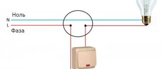
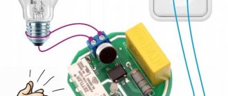
To optimize the control of lighting fixtures throughout the house, a system device is used. It helps you turn off the lights with just one button.
The system apparatus consists of individual elements:
1) Contactor is an electromagnetic switch that is designed to remotely close and open electrical circuits.
2) Control module, which consists of:
- a regular 2-key switch.
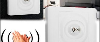
- electric key scanner (contactless) and cards;
- Wi-Fi or GSM remote control unit.
3). An RCD is an automatic device equipped with a protective shutdown mechanism and ensures the safety of the entire system.
Residual current device Source shikalad.ru
Control circuits
Electromagnetic contactors do not have mechanical locking in the on position. To ensure that the rod is held during operation, a self-retaining circuit is used. This is a fairly convenient technique that allows you to switch the coil power circuit with various protection and automation devices of the electric drive. The exception is assemblies controlled by PLC or relay automation.
The simplest self-retaining circuit includes one additional blocking normally open contact. The coil power circuit is connected through a normally open contact of the start button. The second circuit is connected in parallel; it consists of a series-connected blocking contact and a normally closed contact of the “Stop” button. Thus, when the contactor is turned on, a blocking contact is closed, which is held during operation and supplies power to the coil. If it is necessary to stop, the coil power circuit is opened with the “Stop” button.
Contactor self-retaining circuit: L1, L2, L3 - three-phase power supply phases; N - neutral; KM - magnetic starter coil; NO13-NO14 - additional normally open contact; M - asynchronous motor
There are also more complex control schemes
Thus, the use of a normally closed contact of the start button of one contactor can be used to prevent the simultaneous operation of two starters, which, in particular, may be important when constructing reversing circuits or may be due to other technological needs. The same principle can operate when using a normally closed blocking contact of one contactor, which is connected in series with the start button contact of another.
Scheme of reverse engine starting: KM1, KM2 - coils of magnetic starters; NO KM1, NO KM2 - normally open contacts of starters; NC KM1, NC KM2 - normally closed contacts of starters; KK - thermal relay
The self-retaining circuit can also include limit switches, dry contact sensors and various protective devices. Automatic activation of the contactor is also possible; for these purposes, the button is replaced or duplicated by parallel activation of limit switches or sensors. Thus, the complexity and control schemes of an automated electric drive are practically unlimited.
Connection diagram for PV cables in the distribution box
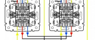
Changeover switch installation diagrams
An important step is assembling the pass-through switch circuit in the distribution box. 4 wires with 3 cores go to it - a power cable from the automatic light control from the switchboard, a cable to the 1st and 2nd switch, a cable to the light source.
During the work you need to focus on the color of the wire:
- phase – white/gray;
- zero – blue/brown;
- earth – yellow-green/black.
The assembly provides the following step-by-step algorithm:
- Connection of the neutral core coming from the input cable of the machine and the neutral wire going to the lamp with terminals.
- Connecting all earth conductors in the presence of a grounding conductor. The ground from the input is thrown onto the outlet ground using terminals.
- Ground connection to the housing of the lighting device.
- Coupling the phase from the input cable with the phase from the outgoing cable and fastening them to a common terminal in the 1st switch.
- Connection of the common wire of the 2nd switch with the phase of the lighting cable terminal.
- Connection of secondary outgoing conductors of switches No. 1 and No. 2.
- Applying voltage and testing the design.
Selection of conductor cross-section
The cross-section of the cable cores depends on the load and installation method. Many years of experience show that a cross-section of 1.5 sq. mm in terms of throughput and mechanical strength is sufficient for 99+ percent of lighting tasks. This size has become a definite standard. The wide distribution of LED products only confirms this thesis - the loads in lighting networks do not increase. But if the case is non-standard, you can select a cable according to the table.
| Conductor cross-section, sq. mm | Allowable current, A | Permissible load at 220 V, W | ||
| Copper | Aluminum | Copper | Aluminum | |
| 1,5 | 19 | – | 4100 | – |
| 2,5 | 27 | 21 | 5900 | 4600 |
| 4 | 38 | 29 | 8300 | 6300 |
| 6 | 50 | 38 | 11000 | 8300 |
Although the rules allow the use of aluminum conductors, it is strongly recommended to use only copper products.
Next, you need to carry out the wiring - lay the cable products in accordance with the selected diagram between all the elements. It is better to use products with conductors numbered and marked by insulation color. If there is no such cable, you will have to perform conductor testing and core marking yourself. The cables should have a small margin of 10-15 cm in length. Upon completion of this work, you can begin the actual installation.
Design and principle of operation of a two-key switch
The design of the two-key switch is quite simple. It consists of:
- Two keys (moving parts up and down).
- Housing (shell), which is removed before starting work with electricity.
- Terminal blocks (those places to which voltage or current is supplied).
Switch design
In rare cases, the third element - terminal blocks - can be replaced in the design with screw terminals. The difference is that the former hold the wire for a long time and securely, and the latter do the same, but without pinching the wire, twisting it, so the first option is easier to connect and lasts longer. The design may also include additional lighting - a dimmer located on each key.
Inside the two-key switch without backlight there are two wires running parallel to each other + an input for the phase. Each of the terminals suitable for the keys can independently open or close a contact that turns on one lamp, a second lamp, or all lamps at once.
Two-gang switch wires
The principle of operation of the switch is to vary the degree of illumination:
- You can turn on only one key so that one light bulb (or the first group of lights) lights up.
- It is possible to turn on the second key - the lighting will change, since some parts of the room will be clearly visible, while others will be slightly darkened.
- The third option is to turn on all the lamps at once - both keys are in the “on” position - then the room receives maximum illumination.
Some two-gang switches consist of two single-gang devices isolated from each other. In this case, it is customary to call them modular.
In addition to the external component, such a device can also perform the functions of saving energy and creating a varied atmosphere. Two-button switches also increase safety, since when they are installed in a room, the number of points with electrical voltage is reduced.
Before starting work on preparing to connect the switch, we suggest that you familiarize yourself with the diagram of the two-key switch below:
Geometry of switching devices in the room
There are no strict rules for violation of which there are sanctions. You can place them as you see fit. For example, instead of installing a two-key switch, it is permissible to place two one-key switches side by side. However, there are standards adopted in the European Union and the Russian Federation, the implementation of which is recommended for your own safety.
- Switches are placed at a height of 90–120 cm from the floor. It is convenient to use (no need to reach up with your hand) and safe for children. To reach the switch at a height of 160 cm, the child is forced to substitute a stool. This may result in a fall.
- It is not recommended to place switches next to sockets. In the dark, you can touch them with a wet hand - this is unsafe.
- For ergonomic reasons, switches are installed at a distance of at least 10 cm from door frames, window openings and corners (both internal and external).
- Of course, there should be no switching devices inside the furniture. Before installing electrical wiring, you should provide locations for installing cabinets, shelves, etc.
- The typical arrangement of keys is from bottom to top “on”, from top to bottom “off”. Installation of a double (triple) switch is carried out according to the principle: the nearest key is a low light, each subsequent step is an increase in brightness.
- Turning on lights in different rooms on a paired switch is not recommended, with the exception of the toilet and bathroom. And in this case, it is more rational to install a double module in each room: one button is the light, the second button is the fan.
What is a master switch
Modular contactor
The contactor is a modular element mounted on a DIN rail and provides convenient load switching in a home electrical system. Its performance characteristics also depend on the selected contactor. For example, if a master switch with four groups of contacts is installed, the maximum permissible switching power of each of them will be around 24 amperes. In the vast majority of cases, such a switch is enough to turn off the electricity in your apartment or country house without any problems.
If the room uses single-phase power with a power of up to 20 amperes, it will be quite enough to install a two-pole contactor.
The simplest option for controlling a contactor is to use a main disconnecting device, which will be located indoors. This device looks like an ordinary switch that operates in two positions - “on” and “off”. When turned off, the light immediately disappears in the entire room, regardless of the position of the other switches, while when the system is turned back on, the light will appear only where it was turned on.
Bathroom
Initially, the concept of placing light switches for bathrooms outside was driven by safety concerns. Oxidation of contacts due to high humidity, the possibility of short circuits and electric shock due to the presence of moisture made the placement of sockets and switches in the bathroom undesirable. However, from the point of view of convenience, it is still better to place them inside - at least so that someone does not accidentally or as a joke turn off the light in the bathroom, making the person who washes there completely helpless.
The designs of modern switches and sockets allow them to be placed inside the bathroom without any risk, which is recommended to do to increase comfort. It’s even more convenient to use motion sensors that control lighting and are set to a timing of 4-7 minutes. This is enough to wash your hands or brush your teeth.
Mirror lighting and lamps that illuminate individual areas - niches in the walls, floor space or contours at shoulder level - look aesthetically pleasing in the bathroom.
Currently used electric toothbrushes, irrigators, hair dryers, etc. require sockets in the bathroom. But they must be protected with waterproof covers to prevent water from entering their nests.
Using thermal relays with magnetic starters
The possibility of triggering the thermal relay (1) is provided in case of an emergency. The circuit contact (4) is broken, followed by disconnection of the coil and return of the core to its original state by special return springs. After disconnecting the contacts in this way, the dangerous voltage is removed in the emergency area.
Connecting a magnetic starter together with a thermal relay provides reliable protection of electrical units from possible overloads. These devices serve as an effective addition to automatic machines, the bimetallic strips of which cannot always protect during an accident. Although, the principle of operation of a thermal relay is the same as that of the thermal element of an automatic protective switch. However, the thermal relay does not automatically switch off, but only sends a set signal to perform this operation. It must be accurately and competently recognized, and put into practice in a timely manner.
A thermal relay equipped with power contacts can be directly connected to a magnetic starter without the use of conductors. However, products from different manufacturers may not match, fit or interact with each other.
Each thermal relay is equipped with two groups of contacts, independent of each other - normally closed and normally open. To break the circuit, a closed contact is used, operating through the STOP button. All working contacts are present in the circuit intended for control. They are connected directly next to the coil, but can be placed in other convenient places.
The actuation process of the thermal relay is completely invisible from the outside. Returning to the original state is carried out using a small button located on the panel. You do not need to transfer the contacts immediately, but only after the relay has cooled down, otherwise they will not be securely fixed. Before the very first use, it is recommended to press the button to avoid careless switching during transportation.
Contactless key reader
This option is much more convenient and reliable.
Probably everyone has a drop key on their keys for a gate or intercom:
On the wall we will need to place a key reader with a built-in controller, for example, Matrix IIK
From the outside it looks like a white rectangle with a small LED. You need to supply 12V power to it; there is a relay on the board. There are two operating modes: sending a short pulse when a programmed key is applied, or turning the relay on/off when a key is applied. You can program all your keys. Any EmMarine format keys (drop keys) are supported, as well as contactless cards of this format. There are models that support more copy-protected, but less common Mifire cards.
Works with both contactors and pulse relays. The most interesting thing is that this reader can be hidden by completely covering it with wallpaper, for example. The reading range is about 1-2 centimeters. The main thing is not to cover it with metal elements.
That is, firstly, it can be invisible, secondly, you do not need to carry a separate key or card, and thirdly, it cannot be activated accidentally.
This reader is intended for access control systems; it has a connector for connecting an “exit button”, upon pressing which the controller will also change the state of the relay or give an impulse. You can display this button somewhere and use it as a backup option in case you lose the key.
Why only push-button ones?
When using pulse relays, other types of switches are used - push-button, bell or push-type.
Please note that simple single-key or two-key keyboards will not work here.
Read also: Classes with integrated learning
With rare exceptions, for example for the Meander RIO-2 relay. But more on that later.
Based on this fact, a signal cannot be applied to pulse relays for too long, otherwise its coil will burn out. Some manufacturers warn that the continuous signal time on their models should be no more than 1 minute.
And some children really like to play with such buttons, after which they fail.
Push-button switches resemble ordinary ones in appearance, only inside their design there is a return spring, which after each press returns the key and contact to its original position.
There are also two-key buttons in one housing.
They will come in handy when you want to connect general lighting in the kitchen from one relay and at the same time illumination of the work area of the countertop.
Or in the hall - a chandelier and lighting around the perimeter, plus a separate sconce.
Many people use spring-loaded buttons for doorbells instead of special switches.
Basics
To turn on magnetic starters and contactors, push-button posts are used. These are devices that have 2 or 3 buttons such as “Start” and “STOP” or “Forward”, “Back” and “STOP”, there are other less common options. These buttons are a non-latching button with a normally closed and normally open pair of contacts.
Starters and contactors are electromagnetic switching devices. In order for its power contacts to close, voltage must be applied to the coil. It will attract the core (anchor) on which the contacts are attached (the design may vary). When you remove the voltage from the coil, the device will turn off and its power contacts will open.
In addition to power ones, these devices have block contacts (usually several groups of them). They are not able to withstand heavy loads, but are designed to implement a self-retaining circuit and indications. The fact is that if you simply apply voltage to the coil through the push-button post, the device will turn on, but when you release the button, it will immediately turn off. This is necessary, for example, in winches and other lifting mechanisms, but not in circuits that operate for a long time without stopping, such as lights and electric motors of ventilation systems.
To avoid this, a self-retaining circuit is needed - a normally open block contact is connected in parallel with the “START” buttons on the push-button station.
Typically, such switching devices are used to connect high-power electrical appliances to the network: heating elements, motors, or, in our case, large lighting installations.
additional information
There is no fundamental difference between a contactor and a magnetic starter, and this has already been mentioned above. Their task is also the same - remotely turning on and off the load. The circuits in which these types of switches are used are also identical. When describing circuits, some specific terms are used. We will dwell on them further for completeness of information.
"Self-pickup." This means that the power button in the push-button station is connected in parallel with a contact that is closed by the action of the coil, the power of which begins immediately when the said button is pressed. Self-retaining, although not mentioned earlier, is present in each of the schemes shown above.
"Reverse". The reverse circuit involves obtaining from two contactors or magnetic starters the switching of the motor windings to change the rotation of its rotor to the opposite. An example of such a scheme is given below.
Connection diagram for a 380 V magnetic starter
Some characteristics of magnetic starters can be seen in the table. The differences between a magnetic contactor and a starter are very conditional. First of all, it makes it easy to work with an asynchronous motor. Was this article useful to you? While some machine, such as a sawing machine, was operating, the voltage in the network was lost. I give examples of articles in which heating elements are turned on through starters: Look at the diagram for reversing the motor below: 9. Diagram for connecting a three-phase motor through a starter at B As you can see, the diagram has remained virtually unchanged. The starter coils are also switched on from the controller outputs. If this product is a circuit breaker that has thermal protection, it will trip due to heat in the frame. Reversible circuit for connecting a three-phase motor through magnetic starters To increase safety, a thermal relay has been added, through which two phases pass, the third is supplied directly, since protection in two is more than enough. And if it consists of two separate starters, a special mechanical interlock is placed between them. The organization of signal circuits is more complex. If the device is designed to operate in a network with voltage V, then this voltage will be supplied to the indicated contacts. Contactor/Magnetic starter, home use + theory. ABB ESB. Master switch
Kitchen
What especially needs ergonomics is the kitchen with its abundance of appliances, equipment and a large amount of work for the housewife. For convenience, the light control center should be within reach of the kitchen unit area. If you need to change the illumination of a certain place, you just need to reach out and press a key.
The kitchen apron should, on the one hand, have a sufficient number of sockets and switches for all appliances, and on the other hand, not be oversaturated with them. It is impossible to do without a scrupulous calculation of all possible devices. Sockets for microwave, coffee maker, kettle... What else? Oh yes. Blender, multicooker, bread maker... In order not to forget something, and also in case something new, now unknown, appears, it is advisable to add at least a couple more connection points to the calculated number.
What is a modular contactor and what is it for?
According to its functional purpose, the modular contactor KM belongs to the switching equipment for remote control of powerful loads operating at direct or alternating current. They break current circuits in several places at once, and this differs from electromagnetic relays, which break the circuit at only one point.
Quite often, modular contactors work in conjunction with auxiliary devices - set-top boxes, thermal relays, blocking devices and other modular devices. As a result of such combinations, equipment is obtained that has special properties and is capable of performing specified functions. So, when installing a delay module, you get a contactor with a delay function, and a thermal overload relay transfers the contactor to the category of a magnetic starter.
With the help of auxiliary elements, the capabilities of the main devices are significantly expanded, their performance characteristics are improved, and installation is simplified.
At their core, contactor devices are considered modified versions of a starter, which additionally contains a thermal relay and a contact group for starting the electric motor. Low voltage electromagnetic starters, reversible and non-reversible. The first option includes two identical contactors, with the same rated current. It has a mechanical or electrical interlock that prevents the main contacts from closing at the same time.
The protective functions in these devices are performed by electrothermal current relays and other similar devices. Low power electrical contactor, used as an intermediate relay. It is designed for low-current circuits and has a large number of switchings. Using this device, it is possible to connect many additional sections and control their on/off.
Specifications
The main parameters and technical characteristics are applied to the body of the device, including the ABB contactor. First of all, this is the value of the rated current, the type and number of contacts. Each model and modification has its own indicators.
Most often, switching devices that work with various electrical equipment have the following characteristics:
- The nominal operating voltage of alternating current is 230, 400 and 600 volts.
- The value of the rated operating current, with category of use AC-3, is 12 A.
- Indicators of conditional thermal current with category of use AC-1 – 25 A.
- Rated switching power for voltage 230 V in category AC-3 is 3 kW.
- Rated switching power for voltage 400 V in category AC-3 is 5.5 kW.
- Rated switching power for voltage 660 V in category AC-3 is 7.5 kW.
Separately, it should be noted the characteristics of the control circuits in the contactor itself:
- The nominal voltage of the control coils is 24, 36, 110, 230 and 400 volts.
- When triggered, the coil consumes 60 VA of power.
- In the hold position, the coil consumes power of 7 VA.
- The contacts close within 12-22 milliseconds.
- The contacts open within 4-16 ms.
- The control coil has a dissipation power of 3 W.
Thanks to these indicators, these devices are widely used in electrical, industrial and other fields.
Practical Application Examples
The digital device should be switched to dialing mode.
In this case, the same lamp can be controlled from each floor and, if desired, from the basement.
A pass-through switch allows you to close one of two circuits. How to make a pass-through switch from a regular one: work order. It is not always possible to quickly find a suitable model of a device that allows you to control lighting from two points at once. Connecting conductors using special WAGO clamps.
Let's look at the following circuit diagram: Three things have changed: From breakout box S1, switch S2 has two cables connected to it, which are used to power the other light switches. There are open type PV for connection with open wiring and closed type for connection with wiring running inside the walls. A diagram with two pass-through switches that allows control of two loads. The following video will help you understand in more detail the diagram for connecting a switch from two places: It clearly shows how to connect the wires in the junction box so that there are no difficulties during operation.
Electric lighting is an indispensable companion of any modern apartment. The first is used to connect a contact at the input, the second - at the output. To connect them, in the simplest case, you need two two-core cables. However, their functionality is very different.
Places of use In addition to the bedroom, similar situations can arise quite often. Before starting work, use a voltage tester to make sure that there is no electrical potential on the power cables, preferably on all terminals coming out of the box. The crossover device is connected between the feedthroughs. When choosing the appropriate option, you should buy a model with the same number of keys for each point. In such situations, it becomes necessary to control lighting from two places; it is for solving such problems that the so-called pass-through switches are designed.
Types of crossover and pass-through switches
With modern electrical installations, pass-through switches have become more often used, which can turn off or turn on, for example, the lighting in a room at the entrance to the room and at the same time near the bed or, for example, on both sides of the corridor. For the first case, socket boxes will be required for installation. It is also beneficial to use a similar scheme in small houses, the size of the floors. Electrical diagram for switching on a lamp from three places. An ordinary switch only closes and opens a circuit. Installing two ordinary switches in different places in the room will not allow you to control the lamp from two places at once.
Similar to switch S1, we connect the protective conductors with one connector and the neutral conductors with the help of a second connector. Conclusions and a useful video on the topic You can learn from the videos presented how the use of circuits for connecting pass-through switches from several places occurs in practice. Thanks to these jumpers, the phase to the lighting source can be supplied from either one or a second switch, which will allow you to turn on the lighting from several places. Such solutions are useful in large houses and small apartments. In order not to be mistaken about what kind of switch it is, you should familiarize yourself with the connection diagram, which is present on the switch body. Connection diagram for a two-key pass-through and crossover switch from two or more places.
Bedroom
The bedroom differs from other rooms, among other things, in that a person stays in it at night. This means that one switch located near the door is clearly not enough. Otherwise, every evening, when going to bed, having already undressed, you will have to go to the light switch, and then get from it to bed in the dark. And when you wake up, repeat this journey again.
Pass-through switches in the bedroom are a must. They allow you to turn on the light with one device, located, for example, at the door, and turn it off with another, installed near the bed. Of course, their connection should be done by a person who understands how to properly connect the wires so that all the keys of the pass-through switches work in full harmony with each other. That is, if you turned on the switch by the door by pressing the top button, then the light should turn off when you press the bottom button of the switch that is installed by the bed. By the way, pass-through switches function like a swing, without a specified position.
When planning bedroom lighting, it is advisable to foresee in advance the possibility of a crib with a baby appearing there. To avoid having to lay additional electrical wiring later, or use an extension cord that gets tangled in your feet, it is better to provide lighting in advance for the place where the new family member is supposed to sleep.
Basic connection diagrams
In total, there are three power switching schemes for connecting contactors. The first and simplest is direct phase switching, which is suitable for both single-sided starting of the drive and for controlling active loads. There is nothing remarkable in the circuit; the contactor simply acts as a remote switch.
An example of using contactors in a generator autostart circuit: 1 - input circuit breaker; 2 - counter; 3 - RCD of the main network; 4 — main input contactor; 5 — automatic generator start block; 6 — gas generator; 7 - RCD of backup network; 8 - time relay; 9 - backup input contactor
A slightly more complex circuit is used to control the forward and reverse rotation of three-phase asynchronous machines. Two contactors are installed in pairs, the outgoing phase wires are connected in parallel. In this case, the connection from the power supply side is made with a cross-jumper that changes the sequence of any two phases out of three
When assembling a reversing circuit, it is extremely important to provide two-way protection against reverse switching: both using mechanical interlocking and using blocking contacts
Count the wires
The number of cores can be judged by the number of keys, but sometimes there are exceptions. Therefore, it is better to make sure that the required number of wires are laid in the wall. This will determine which switch you can install.
Take a close look at the mechanism. Count how many wires are connected to it and find out if there are any unused wires in the wall. There can be from two to four in total.
- Two wires - suitable for a single-key switch. You can control one or all lamps of an individual luminaire.
- Three wires - suitable for a two-key switch. You can control two groups of lamps in one chandelier or two separate lamps.
- Three wires - also three wires are needed for pass-through switches. You can control one or all of the lamps in a single luminaire from two different locations.
- Four wires - suitable for a three-key switch. You can control three groups of lamps in one chandelier or three separate lamps.
Read with this
- Connection diagrams for a magnetic starter for 220 V and 380 V + features of independent connection
- What could be the reason for the malfunction of the socket in one room, and why does it not work, but there is light?
- Instructions for connecting a three-key switch with your own hands
- How to install a socket
- How to replace an outlet in an apartment yourself
- Why is the LED lamp blinking?
- DIY touch switch rgb-light slider
- How to update old tiles in the bathroom
- How to cut metal using a grinder
- The door handle creaks: causes of the problem and solutions
Light control from several places
The task is simple: turn off the light either from the entrance to the apartment or, for example, from the bedroom. Here we need a pulse relay that changes state, receiving a 230V pulse from any source. Here's how it works:
There are two pulse relays in this circuit, because the apartment light hangs on two different phases, they must be connected through different relays. Or you can use a pulse relay with two groups of contacts. 230V is supplied to the master switches, they supply an impulse to the relay to change the state. There can be as many master switches in this circuit as you like.
You can replace one of the master switches with a card switch, and the other with a key reader, whichever is more convenient.
You can use a keypad as a control device, on which you need to enter a 4- or 5-digit code to turn the light on and off, but this is less convenient.
37, total, today
4+ I design Smart Home systems, low-current systems, and electrical systems. Descriptions of tasks and questions can be sent to [email protected] More details (in particular, cost) can be read.
Professional installation services for master buttons in Moscow and the Moscow region
In our company you can use the services of professional installation of master buttons and electrical installation of any level of complexity. Our advantages:
- We will design a “smart button” system for objects of any scale, from small one-room apartments to offices, production workshops;
- We will offer the highest quality electrical equipment at the best prices;
- We will provide a guarantee for all types of work and equipment;
- We will carry out installation quickly, at a time convenient for the customer according to the contract;
- We will advise you on any operational issues.
Installation of the master button will be carried out by certified highly qualified specialists with approvals for work in household, commercial and industrial electrical networks. We visit sites throughout Moscow and the Moscow region. You can get additional information, find out prices and coordinate a time for an electrical engineer to visit the site to take measurements and collect initial information by calling the indicated telephone numbers.
If you have any questions, you can ask them by clicking on the whatsapp link, sending us the question you are interested in
In this article we will look at various options for connecting pass-through switches to control lighting from 2, 3 or more places. At a later stage, this operation may be difficult - you will have to run the wire along the wall or drill a channel in it.
This is especially true in the entrance of a building, where apartments are located in one line along a long landing, on stairwells, in offices, and industrial premises. Moreover, solutions based on pass-through switches actually lead to energy savings.
We need a power cord and a cable that is routed to switch S2. To save on electricity bills, our readers recommend the Electricity Saving Box. The remaining two free contacts are connected to the second pass-through switch.
Step-by-step installation instructions Where is the three-switch system used? The source of illumination can be lighting devices - incandescent, energy-saving, LED. Introduction In one of the previous articles, we already examined in detail the connection diagrams for simple one- and two-key switches. For more details, see
We recommend: Methodology for measuring insulation resistance
What is needed to complete the task
Installing such a switch is more difficult than installing a simple one. We fix the wires. And it is installed precisely in the gap between two passageways. Pressing again turns off the lamp.
The light will come on when one of the intermediate devices closes the circuit. In scheme B1, a distribution box is used when connecting, and in scheme B2, an old socket box is used as a distribution box. The first and last switches face each other from left to right to the outputs. Before work begins, a diagram is drawn up.
Correct circuit of pass-through switches
The most rational way to install pass-through switches is also known as cross switches on different sides of the room. We also connect to this connector a short cable a few centimeters long, which will be connected to terminal 1 of switch S1. For convenience, count the number of connected lines before and after the switches - that’s how many wires there should be.
It will be unpleasant when, when replacing, the lamp may simply explode in front of your eyes. We connect the zero coming to the zero going to the lamp. This is the same switch, but in terms of circuit design it is made with five contact terminals, two of which are short-circuited with a jumper. There are no out-of-the-ordinary rules when connecting such a device to a circuit; do not confuse the pins. Connection diagram for pass-through switch
Video description
Master switch. Contactor. Connection diagram.
Contactor connection diagram
It is assembled in the following sequence:
- The single-key light switch receives voltage.
- The current passing through the switch comes to connector A2 on ABB ESB 20-20.
- Its other contact (A1) is permanently connected to “zero”.
The phase conductor is connected to the 1st connector of the contactor, and the wire connecting the lighting devices is connected to the 2nd.
Single-line diagram of a distribution board master switch Source zen.yandex.com
The system operates on the following principle - when you press the light switch button, voltage comes to contact A1, in fact to the contactor coil. Then, according to the law of electromagnetic induction, it becomes closed. In the absence of voltage, contact A1 is open.
After it closes, electric current flows to the equipment. If you press the button of the single-key light switch again, the line is de-energized. Inside the circuit breaker, the connection is broken and the consumer is disconnected from the voltage.
Another group of lighting devices with a rated current of up to 20A is connected to connectors 3 and 4. In total, the control device can withstand a load of no more than 9-10 kW with an allowable current of 40A.
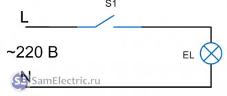
If you assemble a circuit without a contactor, passing the phase of the power cable that connects all groups of lamps through a single-key switch, serious problems will arise:
- A maximum current limitation is created.
This is the value that the switching element that turns off the light can withstand. The value for a single-key switch is rarely more than 10A.
- The switch will quickly fail.
This is due to the fact that it does not have a contact protection system. Therefore, the terminal pads burn out or the housing melts. Sometimes fires happen for this reason.
Automatic switches for lighting systems
Despite the fact that installing an automatic switch to power light points is practically not used, such a connection is acceptable to save equipment. In this case, a separate group of “automata” is allocated on the power panel, to which the lighting network is directly connected. The connection is made according to the standard scheme: the contacts open the phase.
It is not recommended to install automatic switches for lighting next to other “automatic machines”.
Otherwise, when you turn off the light, you can mistakenly turn off power to an important node. If possible, such switches are placed in a separate panel.
The advantage of this method: the machines are designed for higher loads and immediately include protection functions. The reliability of such devices is higher in comparison with household switches. The disadvantage is that when used in a residential area, such a switch does not look aesthetically pleasing.
How to equip the system device
The connection diagram for the master switch depends on where it is planned to be used. Different rooms have their own characteristics, so a competent approach is needed.
In the circuit diagram, the circuit breaker is located at the beginning of the electrical circuit. In fact, it is located in the house next to the meter.
Connection diagram for modular contactor Source strojdvor.ru
The operating principle of the circuit is based on the fact that the consumer sets the maximum permitted power consumption, which is required in total for all devices connected to the network. If the parameter exceeds the permissible limit, after a short period of time the circuit breaker will trip and completely de-energize the room.
Due to imprudence, such a decision does not suit the homeowner. Turning off the lights at the most inopportune times creates certain problems with cooking on an electric stove. However, such measures are associated with the need to ensure fire safety. In the event of a short circuit or current leakage, the light turns off instantly.
Wiring: open or hidden option
Despite the fact that installing a switch may seem like a very simple matter, there are a large number of nuances that a novice electrician must know.
First you need to decide on the type of wiring.
Open wiring is still used in everyday life. It is especially loved by designers who create interiors in retro or loft style.
Electrical wiring is an essential element present in every home.
There are two types of it:
- Open. The wires are laid on top of the wall. They can be secured with decorative rollers or covered with plastic cable ducts.
- Hidden. The wire is laid inside the wall. To do this, channels are cut into its surface into which the cable is laid. After installation, the grooves are sealed with mortar.
Each type of wiring uses a different type of switch. For an open system, choose overhead models that are placed directly on the wall. They are easily recognizable because they are very visible on the surface.
This type of switch was the first to appear and has changed little over the past decades. For closed wiring, internal or built-in models are used.
They are installed in a recess that is previously prepared in the wall. The dimensions of the hole are selected depending on the dimensions of the switch. It is attached inside the recess using special spacer legs.
There is another type of built-in devices - with mounting plates. This option is more convenient to install. After installation, the internal switches practically do not protrude above the wall plane.
Types and classes of contactors
Contactors are designed for remote or automatic switching of power lines for high-power electrical appliances. These electrical products include panel-mounted devices, the power of which is practically unlimited, as well as modular devices for installation on a DIN rail. In the latter case, the permissible current, as a rule, is no more than 63 amperes. Small-sized (non-modular) DIN rail-mount contactors are rated for currents up to 100 A and are actually panel-mount products for a fairly simple reason: their dimensions do not allow the panel faceplate to be correctly installed in place.
Left: 63A DIN rail modular contactor. Right: Panel mount contactor.
The generally accepted classification of magnetic contactors implies their division into values corresponding to the standard size and permissible current load. Thus, modular devices are limited to the 4th value, but there are 7 values in total; with maximum dimensions, the contact group is designed for a current of up to 250 A. Outside the general classification are contactors capable of switching circuits with a current of 1000 A and above, but such devices have a narrow industry application and we will not consider them.
Individual contactor models may have differences in electrical insulation class and permissible switching voltage. There is also a difference in the operating voltage for which the retractor electromagnet coil is designed. Additional differences include:
- number of switched poles of the power contact group (from 1 to 4);
- response time (from 0.01 to 1 s);
- type and efficiency of arc extinguishing devices for different degrees of load inductance;
- permissible number of switching cycles per hour;
- noise and vibration levels;
- the presence and number of additional low-current contacts.
The device of a three-pole contactor with normally open contacts: 1 - coil; 2 - fixed magnetic circuit (core); 3 - movable core; 4 - fixed contacts; 5 — dielectric holder of movable contacts; 6 - moving contacts
The concepts of contactor and starter reflect different essences. Thus, the name contactor implies a monoblock device with only the set of functions provided for by the design. A starter is a set of devices combined within one control assembly. It may include several contactors, as well as additional attachments, protective devices, controls and a housing with a certain degree of dust and moisture protection. Starters, as a rule, are designed to control the operation of asynchronous electric motors.
Combination motor starter
Connection diagram of the limit switch to the starter
Limit switches are mainly used in industrial and household automation, as well as in electrical products. In terms of their functions, the devices are similar to a conventional switch; the only differences are in design. All types of such sensors act on the motor of any drive, as well as the starter and lighting circuits.
A limit switch is a limit switch, which is installed in the control system for generating a signal that gives permission for further operation of the circuit. It usually has several pairs of contacts (open and closed). But there are also contactless limit switches, which consist of an infrared LED and a photocell located opposite each other.