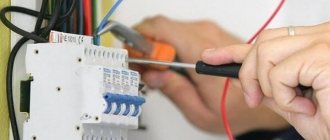
My bitter experience as an electrician allows me to say: If your “grounding” is done properly - that is, in the panel there is a place for connecting the “grounding” conductors, and all plugs and sockets have “grounding” contacts - I envy you, and you have nothing to worry about worry.
Grounding connection rules
What is the problem, why can’t you connect the ground wire to heating or water supply pipes?
In reality, in urban conditions, stray currents and other interfering factors are so great that anything can end up on the heating radiator. However, the main problem is that the tripping current of the circuit breakers is quite high. Accordingly, one of the options for a possible accident is a short-circuit breakdown of a phase to the housing with a leakage current just somewhere on the border of the machine’s operation, that is, at best 16 amperes. Total, we divide 220V by 16A - we get 15 ohms. Just some thirty meters of pipes, and you get 15 ohms. And the current flowed somewhere, towards the uncut forest. But that doesn't matter anymore. The important thing is that in the neighboring apartment (which is 3 meters away, not 30, the voltage on the tap is almost the same 220), but on, say, a sewer pipe there is a real zero, or so.
And now the question is - what will happen to the neighbor if he, sitting in the bathroom (connected to the sewer by opening the plug) touches the tap? Did you guess it?
The prize is prison. Under an article about violation of electrical safety rules that resulted in casualties.
We must not forget that you cannot imitate a “grounding” circuit by connecting “zero working” and “zero protective” conductors in a European socket, as some “craftsmen” sometimes practice. Such a replacement is extremely dangerous. Cases of burning out of the “working zero” in the shield are not uncommon. After this, on the body of your refrigerator, computer, etc. 220V is placed very firmly.
The consequences will be approximately the same as with a neighbor, with the difference that no one will be held responsible for this except the one who made such a connection. But as practice shows, this is done by the owners themselves, because... They consider themselves sufficient specialists not to call electricians.
“Grounding” and “grounding”
One of the options for “grounding” is “grounding”. But not as in the case described above. The fact is that there is a zero potential on the switchboard body on your floor, or more precisely, the neutral wire passing through this very switchboard simply has contact with the switchboard body through a bolted connection. Neutral conductors from the apartments located on this floor are also connected to the shield body. Let's take a closer look at this point. What we see is that each of these ends is threaded under its own bolt (in practice, however, these ends are often connected in pairs). This is where we need to connect our newly made conductor, which will later be called “grounding”.
This situation also has its own nuances. What prevents the “zero” from burning out at the entrance to the house. Actually, nothing. We can only hope that there are fewer houses in the city than apartments, and therefore the percentage of occurrence of such a problem is much lower. But this is again a Russian “maybe”, which does not solve the problem.
The only correct decision in this situation. Take a metal corner 40x40 or 50x50, 3 meters long, hammer it into the ground so that they don’t stumble over it, namely, dig a hole two shovel bayonets deep and drive our corner there as much as possible, and from it draw a PV-3 wire (flexible , stranded), with a cross-section of at least 6 mm. sq. to your switchboard.
Ideally, the “grounding loop” should consist of 3 – 4 corners, which are welded with a metal strip of the same width. The distance between the corners should be 2 m.
Just don’t drill a hole in the ground with a meter-long drill and lower the pin there. It is not right. And the efficiency of such grounding is close to zero.
But, as with any method, there are downsides. You are, of course, lucky if you live in a private house, or at least on the first floor. But what about those who live on the 7th-8th floor? Should you stock up on 30-meter wire?
So how to find a way out of this situation? I’m afraid that even the most experienced electricians will not give you the answer to this question.
What is required for house wiring
For wiring around the house, you will need a copper grounding wire of appropriate length and a cross-section of at least 1.5 mm. sq. and, of course, a socket with a “grounding” contact. Box, plinth, bracket - a matter of aesthetics. The ideal option is when you are doing renovations. In this case, I recommend choosing a cable with three cores in double insulation, preferably VVG. One end of the wire goes under the free bolt of the distribution board bus connected to the panel body, and the other end goes to the “grounding” contact of the socket. If there is an RCD in the panel, the grounding conductor should not have contact with the N conductor anywhere on the line (otherwise the RCD will trip).
How to connect grounding in a panel
It’s hard to imagine coziness and comfort in a private house or apartment without an established power supply system. Electricity consumption is constantly increasing, making it more difficult to protect people and pets from electric shock. Risks can be eliminated and the consequences of injuries can be minimized using a grounding system that connects points of the electrical network or energy consumer to a grounding structure.
Why is grounding needed?
The power cable installed in city houses, as a rule, does not contain a third core intended for output to the protective circuit. There is a simple answer to the question of how to find out whether or not there is grounding in an apartment. It is necessary to disassemble one of the power sockets and make sure that there is a third grounding terminal with a yellow-green insulated wire suitable for it. In its absence, the operation of household appliances with ungrounded metal parts is associated with increased danger.
Example of the need for grounding
When answering the question why grounding is needed, it is necessary to consider the following situations. When operating a washing unit, for example, the insulation of a phase wire may be damaged due to chafing or overheating. If it is laid next to metal parts of the structure, then during strong vibrations their accidental contact is possible. The consequence of this is that a dangerous potential reaches the body of the machine without grounding, touching which a person will receive an electric shock.
Example of the need for grounding
Please note: A similar situation occurs in the bathroom, which in addition to the washing unit has a metal or cast iron bathtub.
When the insulation of a phase wire in a bathroom is destroyed due to high humidity, the risk of electric shock increases many times over. Anyone who is aware of the potential threat of phase breakdown on the housing does not need to explain why it is necessary to ground electrical equipment housings.
Design and purpose of grounding devices
Such structures are divided into working and protective devices.
- The worker is used to organize the safe operation of industrial units. Also common in private households.
- A protective grounding system is required for electrical networks in the residential sector.
Installation of a grounding device (GD) is required in accordance with the Rules for the Construction of Electrical Installations and the Rules for the Operation of Consumer Electrical Installations.
People touching live parts exposed as a result of improper operation of electrical equipment, design defects, deterioration of insulation and other reasons is common. Poor-quality design of the charger and its installation can lead to serious consequences for people: electric shock, burns, disruption of the heart and other human organs, electric shock often leads to amputation of limbs, disability and even death.
The grounding system consists of external and internal parts, which are joined in the electrical panel. An external grounding device consists of a complex of metal electrodes and conductors that drain emergency current from electrical equipment into the ground in places that are safe for people. The electrodes are called ground electrodes. Electrical conductors are grounding conductors; they are pins 1.5 m long and 1 mm in diameter.
They are manufactured industrially from copper or copper-plated steel. Their main advantage is increased current conductivity. They are driven into the ground with hammers or sledgehammers to a depth of 50 cm; contact with the ground must be as strong as possible, otherwise the structure’s ability to drain current will deteriorate.
The simple design is made from a single electrode. Used in lightning rods or to protect remote objects and equipment. In individual farms, preference is given to multi-electrode devices. They are placed in one row and are called linear memory profiles. The standard chain length is 6 meters. They are connected to each other using brass couplings; the fastening is threaded; welding is not recommended. Grounding conductors are installed through terminals. Twisting and soldering of cores are excluded.
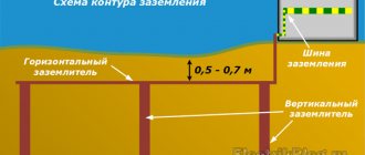
A device such as a ground loop (closed version) is still common. It is constructed at a distance no closer than 1 meter and no further than 10 meters from the house. Placed in a trench in the form of an equilateral triangle. Side length 3 m, depth – 50 cm, width – 40 cm. Grounding conductors are driven into the corners. The same operation is performed with other vertical electrodes (no more than five units). Grounding conductors in the lower supporting part are welded to horizontal products.
They are made of copper, copper or zinc coated steel angle (5 mm flange, 40 mm strip). A standard stainless steel angle of any profile is often used. The products are not painted, as in this case the electrical properties will deteriorate due to weakened contact with the ground.
The design of the circuit is simple; you can do it yourself. But the work is simplified when using ready-made grounding devices on the market, complete with grounding wires. Financial losses will be recouped through the use of high-quality materials that are resistant to corrosion and have a long service life.
Design
The system is made of metal. Structural elements can be water pipelines, gas pipelines and any other metal pipes, as well as a sewer well, steel elements of the building. Ventilation and air conditioning systems are often used for grounding purposes.
Copper for grounding bus in reel
According to the Electrical Installation Rules (abbreviated as PUE), grounding devices can be not only steel, but also copper. Moreover, copper is the best option, since this metal has excellent electrical conductivity, is slightly oxidized under the influence of voltage, and is not subject to rust. It should be noted that steel is used much more often for the manufacture of grounding bars, but this is due to its lower price. It is not recommended to make grounding strips from aluminum, since this metal quickly corrodes and is characterized by insufficient resistance.
Note! The main grounding bus is characterized by a smaller cross-sectional area compared to the protective wire or neutral of the working wire of the power line.
For the PE bus in electrical installations up to 1000 V, the cross-section of the conductors must be different depending on the metal. In the case of a copper conductor, the cross-section must be more than 10 square millimeters, for aluminum this figure is 16 square millimeters, and for steel - 75 square millimeters.
A nineteen-inch copper grounding bus must provide areas for simultaneous connection of 14 or 18 guides. Thus, there will be from 14 to 18 mounting bolts on one strip. The strip is most often equipped with a pair of insulators and is placed in a special cabinet (the so-called cabinet No. 19) and is connected to the ground loop via a PVZ wire. A nineteen-inch bus is used to connect contacts with a cross-section of 2.5 square millimeters.
According to GOST requirements, the main grounding bus must have at least five simultaneous connections.
The grounding device can be made of copper-plated steel. Sheet thickness is 14.2 millimeters. Such a kit will not be cheap, but it will acquire all the properties characteristic of copper conductors.
Note! Fourteen connectors are usually sufficient for ten or more apartments, provided the load is evenly distributed.
Grounding bars are available in two types - REC-ET2-M and REC-ET. The first model is mounted on special profiles in mounting cabinets. But the grounding bus holder, whose galvanic coating protects the product from corrosion, will not work without a special organizer, with which you can connect up to nine consumers.
Connecting the external part of the charger to the shield
To determine the exact procedure for connecting the grounding to the panel, knowledge of the method of using the neutral is required. It can be isolated and grounded. The insulated core is used in networks with increased voltage values of 3-35 kV. With a power supply of 380 V and 220 V, both options work effectively. However, the new PUE rules require the neutral to be grounded. The circuits must be built for voltages up to 1000 V.
Popular grounding systems are TN-C, TN-S, TN-CS. Two-phase TN-C is outdated, but is still used in buildings that have a long service life. Their replacement is associated with technical and financial difficulties. In this circuit, the neutral conductor is used as a protective ground wire. From a practical point of view, for residents of apartments and houses, cable and conductor products with 4 cores are beneficial: their cost is lower and installation work is simpler.
The question of how to connect grounding in a multi-storey building is of interest. The conductors are connected to the common memory bus. The bus is then routed to the electrical panel housing on the floor. The process of converting TN-C to TN-CS in the home panel is similar. The idea is to connect the neutral protective conductors to a single bus of the charger and then attach it with a jumper to the zero bus.
The main disadvantage is associated with the risk of damage to the neutral wire. Then the grounding structure will become unusable. Regulatory documents have introduced a ban on the use of TN-C in new buildings. But it will take decades to completely replace the system.
The principle of operation of TN-S is based on the fact that the zero operating and protective lines are supplied to the consumer by separate conductors from the transformer substation. In the Russian Federation and CIS countries, an intermediate version of TN-CS is common, in which the conductors are separated directly upon entry into the house. In both options, the safety functions are performed by a residual current device (RCD).
Correct connection
To carry out grounding in an old apartment building in accordance with current requirements, it is necessary, first of all, to change the two-wire wiring to three-wire (along with the phase and neutral wires, there must be a PE grounding wire). To install new wiring, it is important to use a high-quality three-core cable, for example, VVG or NUM.
It is best to ground a multi-storey residential building not with a separate apartment, but together with other residents. This will significantly reduce costs for each individual resident. If necessary, the installation of a grounding loop for an apartment building should be agreed upon with the management company. It is recommended to install the circuit itself not along the facade, but along the back side of the building. The grounding conductor is routed throughout the apartments and connected in the panels using a copper busbar. The size of its cross-section must be no less than the cross-section of the PEN core in the cable supplied to the input distribution device of the house.
Errors when installing memory
Typical disadvantages often encountered in practice include:
- Use as a contour of metal fences or masts. Current resistance is not taken into account and creates the risk of severe electric shock to people in the event of an accident in the system.
- Connecting the circuit directly to the housing of electrical appliances, bypassing the grounding bars in the panel.
- Installation of separate switches in the neutral conductor. If the device fails, electrical appliances may become energized. Sometimes the neutral wire contact is not strong. The consequences are the same.
- Use of products of smaller cross-section or thickness for grounding conductors. Such electrodes quickly fail under the influence of corrosion.
- Use as a grounding conductor for the working “zero”. There is an increased likelihood that the system will be energized.
- Location of horizontal grounding conductors on the surface of the earth. In the event of an accident, the affected area will increase.
- Ground connection to the heating pipe. It is impossible to say which direction the stray currents will take, since the situation in the neighboring apartment is unknown. The likelihood of electric shock to strangers increases.
Upon completion of installation work, the system is checked. Attention is drawn to the value of current dissipation resistance. To carry out this work, it is advisable to involve a specialist with the appropriate equipment.
Application
The grounding bus is used as an integral element of the protective circuit when diverting power lines to apartment buildings and industrial buildings. Grounding serves the function of protecting humans and other living organisms from the effects of current when electrical appliances are running. Busbars are used in systems with power up to 1000 V.
The bus is designed to act as a connecting element for many conductors at the same time, and also ensures the operation of the entire grounding system of the structure. The main grounding bus (GGB) is assigned the function of equalizing potential indicators in the electrical network. Thanks to this element, the conductor is separated and the contacts are connected. The contacts transmit electrical discharges, which is required for the normal functioning of individual systems in the building.
An example of a metering board with an RCD for a private house | TT grounding system
Installing a selective residual current device (RCD) in the metering panel of a house can significantly improve fire safety. This is especially true if you use a grounding system - TT
In this article we will look at the step-by-step assembly of the metering board diagram for a private house in which an RCD is installed . This assembly complies with the Technical Specifications, which are most often issued by energy supply companies:
– Dedicated power 15 kW
-Input cable – SIP – Self-supporting insulated wire (4 pcs: 3 phases and PEN)
– An additional grounding loop in the area from which a 1x16mm.sq. conductor is laid to the shield.
The circuit is designed for the type of CT grounding , in which the PEN coming from the transformer becomes a working ZERO, and the protective zero (grounding) is taken from an additional circuit mounted on the site. They are not connected to each other anywhere.
We have already considered the option with the TN-CS system, where the neutral and grounding are brought to one point in the shield, only after which they are separated.
All common metering panel assemblies, including those with surge protectors and those with a socket, for different grounding methods, are available HERE.
Housing installation
When installing outside the home, it is recommended to use steel electrical panels (No. 1 in the image), which can be locked. The degree of protection from dust or moisture must be at least IP54.
Typically, the shield is mounted at the boundary of the site, for example, on a power line support, a building wall or a fence. Depending on the ease of access to it for inspectors. It is best to bring wires and cables inside for switching, preferably from below, using sealed leads. This way you will ensure maximum tightness and significantly protect the electrical installation as a whole.
All modern switchboard equipment is mounted on DIN rails. Make sure that the shield you purchase has them installed or included. Otherwise, you will have to buy an additional DIN rail.
Built-in buses
It is not necessary to create a design from scratch; you can purchase a ready-made device with built-in ground buses. An example is a DIN rail, which is a set of dismountable equipment in a metal box. A special 220 V switch is attached to the yard, providing power to the device. The panel kit includes a DIN rail, zero busbars (three units) with an insulator. It is possible to connect up to 22 consumers at the same time.
Panel 19″ with DIN rail KP series
There are three types of rails on the market: DIN U3 for circuit breakers, DIN U3 - also for circuit breakers, but the kit also includes a zero bus with grounding. You can also purchase DIN U4, equipped with additional functions (for example, the ability to install an electric meter). All DIN rails are coated with anti-corrosion material.
One of the popular DIN rail options is TLK-ERH-CU. The nineteen-inch product is made of copper. This model is characterized by its low cost and decent level of quality.
Source
Installation of a box for an input circuit breaker
In order to prevent unauthorized connection, bypassing the electric meter, all switching and protective devices located before it must be closed in boxes (No. 2 in the image) and sealed.
So, during installation, we first install a special housing for the AB (circuit breaker). It differs in that it has “ears” for easy filling. In a three-phase 380V network, the box is installed on at least three modules so that the Circuit Breaker fits there.
Tips and tricks
If the user does not know what to do when there is no grounding in the apartment, he is offered a choice of two options for solving the problem.
- Agree with your neighbors and build a protective circuit yourself.
- If it is impossible to do this, protective devices (RCDs) are installed in the supply lines.
In conclusion, we note that when arranging the circuit, it is important to adhere to the requirements and recommendations of the PUE regarding the laying and cross-section of grounding conductors and busbars. And when installing an RCD, you must ensure that a separate device is in the line supplying the bathroom.
Please click on one of the buttons to find out if the article helped or not.
Installation of the machine
The input machine (No. 3 in the image) is installed in a separate housing, which is closed with a casing. Later, representatives of the energy sales company will seal it, install a seal and check it every time readings are taken or control rounds are taken.
For three-phase 380V networks, with an allocated power of 15 kW, the rating of the circuit breaker should be 25A.
Installation of accounting and security devices in the panel
Now it’s time to install all the other elements on the DIN rail. The complete list of equipment required for the panel of a private house is as follows:
1) Steel electrical panel (protection rating IP54 or higher)
2) Box/casing for AV for 3 modules
3) Three-pole circuit breaker 25A
4) Three-phase electric energy meter 380V
5) distribution block for DIN rail
6) Selective RCD from 40A, leakage current 100mA or 300mA
The electricity meter must be three-phase, for 380V networks. Usually electronic, two-tariff is chosen. When choosing a manufacturer, the main guideline is the warranty period; the one with the longest warranty should be taken. Usually a simple one is taken, without unnecessary interfaces, for example, Mercury or Energomera.
The distribution block must have a sufficient number of terminals for the required conductor cross-sections. For the option with a VDT - residual current switch, with CT grounding, you will need:
1 terminal – 16mm.kv – for re-grounding circuit PV1 or PuV (PuGV)
2 terminals of 6mm.kv - for internal conductors used for switching
The fire protection RCD is selected selective - having a delay when triggered. The leakage current can be either 100mA or 300mA.
The choice of the response threshold of the Residual Current Device depends on many factors. Almost any electrical appliance has some leakage and this is normal. If there are many such devices, the total losses can be large.
Based on this, this value is selected. If the housing is small, it is enough to set 100mA. If this is a cottage, with a lot of technology and equipment, then definitely 300mA.
For internal connections in the panel, it is most convenient to use flexible wires PuGV (also called PV-3) 1x6mm.sq. and NShVI tips.
Design features of the rack
The structure of the main grounding bus directly depends on its subsequent placement. If an input device is used for installation, then in this case it is best to use a PE bus created specifically for this purpose. It will have direct contact with the body of the ASU cabinet, made of metal.
In another case, the main grounding bus is mounted outside the input device, near it, in the most accessible, open place, convenient for maintenance and repair by specialists. The penetration of unwanted subjects into slats placed in an open manner is limited by placing the entire structure in a special box that is securely locked with a lock. A warning sign is placed on its door.
In accordance with regulatory documents, steel or copper material with specified dimensions must be used for the production of gas shields. In the case of outdoor installation, the dimensions are selected so that the structure can accommodate the required number of holes for contacts for bolted connections. For example, a typical factory-made product GZSh XX-UHL4 TVS has strictly standardized dimensions for the thickness and width of the rack: 3x30, 3x40, 4x40 mm. The length is calculated based on the established number of holes for attaching conductors: 10, 15 or 20 pieces.
It should be remembered that aluminum strips for slats are not manufactured, and those made by hand are not allowed for use. In addition, the main grounding bus with certain parameters must have dimensions no lower than the cross-section of the PE bus used within the electrical panel.
Structurally, the slats are made in such a way that it is possible to connect additional wires to them at any time using ordinary tools. If the facility has to use several inputs at once, then the main grounding bus is mounted in each such place. At the same time, a rack connection is formed, connected to the potential equalizers.
Assembling an electrical metering panel with an RCD
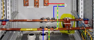
connecting the input cable SIP 4x16
First of all, we connect all the large cross-section wires . In our case, these are Self-Supporting Insulated Wires (SIP). Only four pieces. They are all aluminum, with black insulation on the outside. Their markings are made in the form of a continuous colored stripe.
We connect the yellow, green and red conductors to the upper terminals of the input AB - these are three phases. PEN – with a blue stripe, to the zero terminal of the electric energy meter.
Usually these are the two on the far right. You can connect to any of them, they are internally connected.
Earthlings
Next, we connect the grounding conductors to the distribution block. First of all, as the largest, from the circuit mounted on the site. There is also grounding of the current-conducting body of the shield, which is mounted under a special bolt.
It is this connection scheme of N and PE that distinguishes the TT system from others.
In the TN-CS system, the metering board diagram with an RCD, which we have already reviewed HERE, everything is done differently. There, on the contrary, both the PEN conductor and the grounding loop of the house are combined in the distribution block. And only after that they share.
Here, the input SIP with a blue stripe - PEN, is essentially the working zero “N” of the entire electrical installation. The protective zero, also known as “PE” grounding, is taken from a circuit mounted in the yard.
Location
At its location, the grounding bus can be located both in the internal part of the input device and not far from it. If the grounding is located inside, it is wiser to use a PE bus. A PE wire is connected to this device, at the other end of which there is a main grounding bus. Moreover, the electrical conductivity of the conductor must be equal to or exceed the conductivity of the PE wire of the power supply line.
Advice! It is recommended to arrange grounding at the planning stage of a residential building or other structure.
Wherever the grounding bus is installed, all its parts responsible for potential equalization must comply with GOST 10434. These rules apply to second-class contacts.
Wires from the input machine to the meter
The next step is to lay the wires from the lower terminals of the input machine - 3 phases and connect them to the corresponding contacts of the electric energy meter.
We discussed in detail how to connect a three-phase electricity meter, in what order to connect the wires HERE, using the Energomer CE 306 device as an example.