The electromagnet was invented 200 years ago and since then little has changed in its design. But now there is more knowledge and technological capabilities to make miniature electromagnets with low power consumption, with the ability to supply DC or AC power and other features. Electromagnetic relays (or simply relays) are components that are most often enclosed in a rectangular housing with leads for soldering or mounting into a socket. Inside there is an electromagnet, a metal armature that moves the contacts.
Coil supply voltage
On the relay body it is written, for example, 12 V, which means that it will require 12 V to operate. But the voltage is rarely exactly the required value. And what should you do if the voltage in the circuit drops to 9 V or rises to 15 V?
If the voltage is too high, the solenoid coil, usually sealed in a small plastic housing, will simply overheat. Joule's law is inexorable here. Fortunately, manufacturers provide some voltage reserve. Conversely, if the voltage is too low, less current will flow through the constant resistance coil, making the armature less weak in pulling. And if the current is too low, the armature will not budge at all.
The term "coil supply voltage" is imprecise because every relay manufacturer must provide at least two different coil voltages. The first is the actuation voltage, and the second is the release voltage. The switching voltage is close to the voltage indicated on the housing.
This is the value at which the manufacturer guarantees contact closure. It is given for a strictly defined temperature, most often room temperature or similar. At higher temperatures, the resistance of the wire increases, so applying the same voltage to the coil will cause a lower current to flow (which may not be enough to move the armature).
The cut-off (release) voltage informs to what value the coil supply voltage must be reduced in order for the contacts to return to their original position. Often this is only 10% of the rated voltage! Thus, a relay with a supply voltage of 5 V, indicated on the case, will turn off when the voltage drop drops to 0.5 V, which is even less than the forward voltage of the silicon pn junctions. The difference in percentage is caused by magnetic hysteresis of the ferromagnetic material from which the electromagnet core is made.
This is very convenient because it can significantly reduce the power consumption of the coil in steady state. A relay with a nominal supply voltage of 12 V is sufficient to supply voltage above 8.4 V and then decrease it (for example to 2 V). The energy savings important for battery-powered circuits will be enormous.
The actual coil supply voltage may differ from that indicated on the case, and within a fairly wide range. This is worth remembering. By tightening the armature with an electromagnet, you can reduce the supply voltage to the coil and save energy.
Indications for use
Solid state relays are recommended for use in cases where standard devices cannot cope with their obligations. For example, when they melt or burn during the switching process.
With the help of TSR, the reliability of the circuit and the timely supply of voltage to the load are guaranteed. Unlike simple devices, it is not a problem for SSRs to cope with an inductive load.
In addition, a solid-state device should be used when there is a shortage of space during the installation process and when there are high requirements for circuit reliability.
Maximum switching power
When searching for relays on store websites, you can come across descriptions such as “maximum switching power: 4000 VA.” This corresponds to the value specified by the manufacturers in the notes and means the product of the maximum current times the maximum voltage that a given relay can carry. For 16 A and 250 V AC, this is exactly 4000 VA.
It's actually a useless number. This is indicated by a diagram of the voltage in the switched return circuit versus the current (maximum switched power). While for AC the parameters like 16A and 250V AC are correct, for DC it is not so much the case.
Direct current has a very undesirable feature for contact elements. When they are turned off (opened), an electric arc occurs, which does not go out immediately, but continues until the distance between the contacts becomes large enough.
During the arc, the contacts melt, just like when welding. Alternating current is "gentler" in nature because the voltage between the contacts will drop to zero in a maximum of half a cycle, which for circuits operating at 50 Hz is only 10 ms. Consequently, the maximum power that can be switched by the same relay placed in a DC circuit will be significantly lower than the “variable” 4000 W. At 300V high voltage, the maximum current can only be 200mA, so the load will only consume 60W.
Most medium power relays on the market are designed to operate on AC circuits (especially in the lower price range). Direct current requires the relay to be equipped with additional elements that speed up the extinguishing of the electric arc, which increases its cost.
The minimum forward current and minimum switched power parameters are often indicated not directly in the notes, but in the form of comments. For example, in the specification for a typical relay, only on the third page you can find information, written in small letters, that the minimum switching voltage is 5 V DC, and the minimum switching current is 10 mA (in relays with gold-plated contacts). These conditions must be met simultaneously.
The reason for this limitation lies in the very nature of the operation of the contact elements. When they conduct electricity at a high enough intensity, the sparks generated when they are connected and disconnected can clear their surface of oxides, sulfides and other impurities. This is called the self-cleaning effect. To do this, relay manufacturers must select the force with which the contacts are pressed against each other so that this layer can wear off.
If this process is not performed properly, contact resistance may slowly increase until current conduction problems occur. The effect is especially noticeable when using relays designed to switch medium or high power loads, in places where flowing currents can be traced, for example in the audio signal path.
The phenomenon is even more visible when the relay does not have a sealed housing and the atmosphere inside it contains pollutants from the air (the main culprit here is sulfur and its compounds). Therefore, so-called small-signal relays must have a sealed housing. Only in this case can we guarantee that they will work properly for many years in environments with varying degrees of pollution.
In addition, the contacts should be coated with a suitable metal. Gold is most often used for electroplating, but there are also alloys of silver and palladium, which are characterized by much lower resistance.
SSR connection
When connecting the relay, polarity must be strictly observed.
Voltage is supplied to the control inputs. Loads are connected to the output terminals. Connections are made using screw connections (no soldering).
When connecting voltage, make sure that the switching is carried out correctly.
It is not allowed to place devices near flammable materials.
The relay housing may become hot during operation. When the temperature rises above 60°C, install the SSR through a cooling radiator.
Connection diagram
Contact transmission current
Both the contacts and the metal leads to them are elements with a finite cross-sectional area. There is a limit to the amount of current that can pass through them without fear of overheating.
The value of this parameter is influenced by the shape of the contacts, the contact surface, the material of the contacts and the force of their pressure. For both normally open (NO) and normally closed (NC) contacts, the identity of the first three parameters is easily achieved. It is enough if they are made of the same material, using the same shapes.
The pressing force parameter is more difficult to repeat. The contacts are impacted with great force and are then held in place by an armature. The pressure on the closing contacts is provided only by a spring, which should not be too strong so that the relay electromagnet can bend it. For this reason, the current that the NO contacts can carry may be greater than the current flowing through the NO contacts. Some manufacturers actually stipulate that the maximum forward current of the closing contacts is available at the rated coil supply voltage. Many manufacturers take this into account and design their products in such a way that there is no difference in parameters between normally open and normally closed contacts.
Relay load type
The maximum forward contact current is a parameter that may differ for DC and AC. It can also differentiate between resistive and reactive loads. More often than not, a resistive load can draw more current than a reactive load.
Some manufacturers provide more detailed specification in their relay notes, such as taking into account motor load. For example, despite the high maximum forward contact current, which reaches 16 A, the maximum power of the controlled motor can be only 650 W. The reason is simple - inductive loads pose a problem for contacts due to the resulting overvoltage and inrush currents. Therefore, a seemingly “strong” relay may not be enough.
Where are they used?
Solid state relays are unique devices that do not require special maintenance after installation. The “set it and forget it” principle works here. For example, in simple models, the contact group is cleaned at a certain frequency - usually after a certain number of cycles. If the product is used infrequently, this does not cause problems.
But what about equipment that requires frequent activation—once per second or even more often? An example of such a technique is a machine with solenoid-type valves.
The voltage is supplied through a relay, which has to break up to ten amperes of inductive I. If you install a contact device, it will have to be replaced every 1-2 months. If you install a solid-state analogue, you can forget about it for many years.
Despite the reliability of operation, TSRs require periodic inspection. Basic recommendations in this matter are provided by the product manufacturer. As a rule, we are talking about checking the fact of contact closure, the integrity of the housing and insulation.
Switching time
It is clear that relays operate slower than semiconductor devices. In some devices it is necessary to enter the appropriate switching sequences. The same passive volume controls. Switching resistors quickly in the resistor divider is necessary to achieve a smooth feel when the audio volume changes quickly. The thing to remember here is that leaving the circuit open even for a moment, when one relay has already switched off and the next one has not yet activated, can lead to a very unpleasant crackling sound from the speakers. This is unacceptable in high-end audio equipment, and in a recording studio it is generally nonsense.
The time it takes for the next relay to turn on before the previous one stops working should be taken into account. And take into account the possible deviation of the supply voltage towards a decrease, as well as increased ambient temperature, which increases the switching time. Therefore, it is better to assume that the time is twice as long as indicated in the datasheets on the relay.
Connection diagrams
Electrical circuits are constructed depending on the characteristics of the load connection.
The most common schemes include:
- Open or open . When a control signal is present, the relay is energized. When the inputs are de-energized, the devices are in a switched off state.
- Closed. In the absence of a control signal, the relay load is energized. When the inputs are de-energized, the connected devices are in working order.
- Three-phase - contacts are connected according to the “Star”, “Star-neutral” or “Triangle” circuit.
- Reversible - include two levels of control. Manufactured in a three-phase version.
Electrical circuits with solid-state relays are assembled exactly according to the diagram, observing polarity.
Incorrect connection of devices can lead to electric shock or failure due to short circuit.
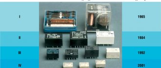
Electromagnetic relay housings
Relays with sealed housings are becoming increasingly popular, but relays are still available in a non-sealed housing in the form of a plastic cover mounted on latches. When designing equipment for home or office use, this is not particularly important. But in polluted or damp environments it is worth paying attention to.
Of course, only sealed relays should be placed in an environment with high humidity. But there are also rooms with completely different specifics, for example, boiler rooms. The air in them is usually dry and warm, but polluted with coal dust and exhaust gases. The impurities are rich in sulfur, which is an integral companion of all types of carbon. If combustion in small boiler rooms has a negligible impact on the environment, the electronics inside the boiler room can sense this immediately. Most medium power relays have silver alloy contacts, which ideally react with sulfur to form silver sulfide, which is insoluble and non-conductive. That is, the relay contacts become sulfated in a short time.
This situation arose in the controller of a thin central heating furnace, where relays without sealing were used. After two years, the furnace began to “work strangely” and finally stopped turning on the pumps. The reason is highly sulfated relay contacts. Inside they were sticky with resinous dust. After replacing it with a sealed casing, the oven operates flawlessly for many years.
In their notes, manufacturers draw attention to the use of relays with a non-sealed housing only in places free from dust, sulfur and nitrogen compounds. This also affects the sealing class - units with a sealed housing usually have an IP67 class, while regular ones only have IP40.
Installing the element into the connector
Relays are electromechanical components and are therefore subject to wear and tear. In most commercially produced devices this can be neglected - the service life of the relay is usually longer than the expected service life of the device. Even if the relay fails (for example, when welding contacts) or wears out prematurely, it is a simple and routine operation to replace the component at a service center.
The situation is different with industrial automation devices. In cases where solid state relays (SSRs) cannot be used or the device is not new, the only option left is to replace the relay regularly. Please note that devices often operate in very poor conditions, such as high humidity (causing terminal corrosion), vibration, dust (deteriorating insulation), or extremely high or extremely low temperatures. Then there is nothing left to do but use the relay socket. Some have terminals that allow both soldering into a circuit board and mounting into a socket with a clamping clamp to prevent them from falling out.
In many sockets, the contacts are located at the same distance as the relays installed in them. Thanks to this, you can add a relay socket to the device without changing the design of the printed circuit board. This is especially important when at the design stage it is not known whether a given relay will often fail. Please note that a relay built into a socket usually has a lower permissible direct contact current.
Bistable and monostable
Bistable relays are becoming cheaper and more accessible, but many developers are not yet paying attention to them. In mains-powered circuits, energy efficiency is not very important, but where energy savings are required, they can be of great help. No energy is required to hold the anchor in one position. Current consumption occurs when switching contacts, which lasts several tens of milliseconds, after which its source can be turned off. The device will remain in a stable state for as long as necessary, hence the name.
Typical relays have only one stable position, and maintaining the other requires continuous flow of current through the coil.
There are two types of bistable relays: with one coil and with two. In the case of two-coil relays, everything is simple, because one of them is used for “on” and the other for “off”, that is, to switch contacts in positions 1 and 2.
Bistable relays are available as low power or medium power relays for switching mains powered devices with a current draw of several amps. Almost every major company involved in the production of relays has them in its offer, so the choice is really wide.
Use in electronics
In addition to protecting electronics from the destructive consequences of coil switching (meaning the self-induction pulse that occurs when the current in the coil decays), it is also worth protecting it from interference created by sparking contacts. Microcontrollers operating near relays are especially affected, which can cause program failure. Observations indicate that this is especially true for high inductance loads such as 220 VAC solenoid valves. An example of such a protection circuit is an RC series circuit. These may be other configurations including, for example, a junction diode or, in DC circuits, a fast-acting semiconductor diode.
Design features
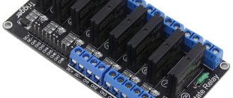
The solid-state relay is based on an electronic board, which includes three main elements - control and isolation units, as well as a power switch. The following parts are used as power elements:
- For constant I - field-effect transistors, simple transistors, modular elements of the IGBT class, as well as MOSFET transistors.
- For variable I - assemblies based on thyristors, as well as triacs.
Circuit decoupling is provided by optocouplers - products consisting of a light-emitting and light-receiving device. A dielectric having a transparent structure is installed between them.
The control unit is made in the form of a stabilizing circuit that provides optimal current and voltage levels for the light-emitting element. The voltage at the circuit input should be from 70 to 280 Volts.
As for the load voltage, its value is up to 480 Volts. The location of the electrical appliance (before or after the TTR) does not matter.
As a rule, the device is mounted after the load and then connected to ground. With this version of the circuit, it is possible to protect the internal elements from the flow of short-circuit current (it will flow through the grounding wire).