Calculation result
As a rule, it will turn out that resistors with this value are not produced, and you will be shown the nearest standard value. If you cannot make an accurate selection of resistance, then use a larger value. A suitable value can be made by connecting the resistance in parallel or in series. You don't have to calculate the resistance for an LED if you use a powerful variable or trimming resistor. The most common type is 3296 at 0.5W. When using a 12V power supply, up to 3 LEDs can be connected in series.
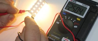
Resistors come in different accuracy classes, 10%, 5%, 1%. That is, their resistance can vary within these limits in a positive or negative direction. Do not forget to take into account the power of the current-limiting resistor, this is its ability to dissipate a certain amount of heat. If it is small, it will overheat and fail, thereby breaking the electrical circuit. To determine the polarity, you can apply a small voltage or use the diode test function on a multimeter. Different from resistance measurement mode, usually supplied from 2V to 3V.
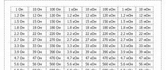
Table of the dependence of the operating voltage of the LED on its color.
Also, when calculating LEDs, you should take into account the spread of parameters; for cheap ones they will be maximum, for expensive ones they will be more the same. To check this parameter, you need to enable them under equal conditions, that is, sequentially.
By reducing the current or voltage, reduce the brightness to slightly glowing points. Visually, you will be able to estimate that some will glow brighter, others dimly. The more evenly they burn, the less spread. The LED resistor calculator assumes that the characteristics of the LED chips are ideal, that is, the difference is zero.
The drop voltage for common low-power models up to 10W can be from 2V to 12V. As power increases, the number of crystals in a COB diode increases; each has a drop. The crystals are connected in chains in series, then they are combined into parallel circuits. At powers from 10W to 100W the reduction increases from 12V to 36V. This parameter must be indicated in the technical characteristics of the LED chip and depends on the purpose of the color:
- blue;
- red;
- green;
- yellow;
- three-color RGB;
- four-color RGBW;
- two-color;
- warm and cool white.
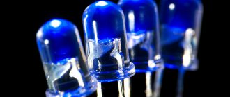
LEDs.
Before choosing a resistor for an LED using an online calculator, you should make sure of the parameters of the diodes. The Chinese sell a lot of LEDs on Aliexpress, passing them off as branded ones. The most popular models are SMD3014, SMD 3528, SMD2835, SMD 5050, SMD5630, SMD5730. For example, most often the Chinese cheat on SMD5630 and SMD5730. The numbers in the markings only indicate the case size of 5.6mm by 3.0mm.
In branded ones, such a large case is used to install powerful 0.5W crystals, so buyers of SMD5630 diodes directly associate it with 0.5W power. The cunning Chinese takes advantage of this and installs a cheap and weak crystal in the 5630 case with an average power of 0.1W, while indicating the energy consumption of 0.5W.
A good example would be car lamps and LED corn lamps, which contain a large number of weak and low-quality LED chips. The average buyer believes that the more LEDs, the better the light and the higher the power. Car lamps on the weakest ice 0.1W To save money, my LED colleagues are looking for decent LEDs on Aliexpress. They look for a good seller who promises certain parameters, order, and wait a month for delivery. After tests, it turns out that the Chinese seller cheated and sold junk. You'll be lucky if the seventh time you get decent diodes and not junk. Usually they make 5 orders, and without achieving results, they go to place an order in a domestic store that can make an exchange.
Material on the topic: how a toroidal transformer works and what are its advantages.
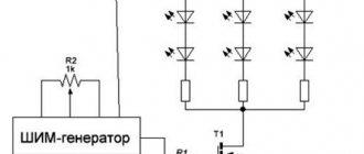
Serial connection
Assembling a working circuit using one LED is not difficult. It's another matter when there are several of them. How to correctly connect 2, 3... N LEDs? To do this, you need to learn how to calculate more complex switching circuits. The series connection circuit is a chain of several LEDs, in which the cathode of the first LED is connected to the anode of the second, the cathode of the second to the anode of the third, and so on.
A current of the same magnitude flows through all elements of the circuit:
And the voltage drops are summed up:
Based on this, we can draw conclusions:
- It is advisable to combine only LEDs with the same operating current into a series circuit;
- if one LED fails, the circuit will open;
- The number of LEDs is limited by the power supply voltage.
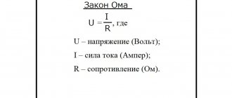
Calculating an LED Resistor Using Ohm's Law
Ohm's law states that the resistance of a resistor is R = V / I, where V = voltage through the resistor (V = S – VL in this case), I = current through the resistor. So R = (VS – VL) / I. If you want to connect several LEDs at once, this can be done in series. This reduces energy consumption and allows you to connect a large number of diodes at the same time, for example, as some kind of garland. All LEDs that are connected in series must be of the same type. The power supply must have sufficient power and provide the appropriate voltage.
It will be interesting➡ How is parallel and series connection of resistors different?
Calculation example: Red, yellow and green diodes - when connected in series, a supply voltage of at least 8V is required, so a 9-volt battery will be an almost ideal source. VL = 2V + 2V + 2V = 6V (three diodes, their voltages are summed). If the supply voltage VS is 9 V and the diode current = 0.015A, Resistor R = (VS – VL) / I = (9 – 6) /0.015 = 200 Ohm. We take a 220 Ohm resistor (the nearest standard value, which is larger).
Avoid connecting LEDs in parallel!
Features of cheap LEDs
Comparison of Chinese and branded LED strip
Low cost in itself is not proof of poor quality. Expanding the scale of production and improving technological processes reduces costs. However, in the corresponding market segment there are products from manufacturers that do not actually meet the declared characteristics.
To identify possible problems, pay attention to the following parameters:
- in cheap models, the main parts of the structure are made of aluminum;
- copper analogs are heavier, remove heat more efficiently, and are resistant to mechanical stress;
- in a quality product, the crystal size corresponds to the standard (0.762 x 0.762 mm or another);
- the disadvantages are indirectly indicated by the distortion of the proportions of the working area (rectangle instead of square);
- To increase reliability, responsible manufacturers increase the number of conductors and use threads made of noble metals.
High-quality LEDs create a luminous flux of 150-220 lumens per 1 W of consumption. Fakes - no more than 50-70 lm. When in doubt, you should select protection components with particular care.
LED as a nonlinear element
Let's consider a family of current-voltage characteristics (CV characteristics) for LEDs of various colors. This characteristic shows the dependence of the current passing through the light-emitting diode on the voltage applied to it. As can be seen in the figure, the characteristics are nonlinear.
This means that even with a small change in voltage of a few tenths of a volt, the current can change several times. However, when working with LEDs, they usually use the most linear section (the so-called working region) of the current-voltage characteristic, where the current does not change so sharply. Most often, manufacturers indicate in the LED characteristics the position of the operating point, that is, the voltage and current values at which the declared brightness is achieved.
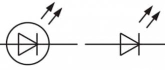
The characteristics presented above were obtained for light-emitting diodes connected in the forward direction. That is, the negative pole of the power supply is connected to the cathode, and the positive pole is connected to the anode
Safety precautions
Briefly about the nuances of the connection, which is carried out in most homes - to ensure safety when working with an electrical circuit, it is often not enough to turn off just the switch. The fact is that it, as a rule, opens the phase, but due to the lack of grounding, a residual voltage remains at zero. If the grounding is incorrect, for example, people connect to a battery or water supply, there is a risk of getting voltage between the phase and ground. Turn off the power completely at the switch or meter at the entrance to the house or apartment, and make proper grounding if you do not have one.
Calculation of a resistor for an LED
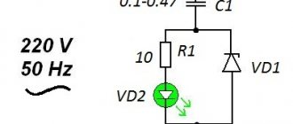
Calculating the resistor for an LED is a very important point before connecting the LED to the power source. After all, how the LED will work depends on this. If the resistor has too little resistance, the LED may fail (burn out), and if the resistance is too high, the LED will emit weak light. The resistor for the LED is calculated using the following formula:
- R = (VS – VL) / I
- VS – power source voltage (V).
- VL is the LED supply voltage (usually 2 volts and 4 volts for blue and white LEDs).
- I – LED current (for example 10 mA = 0.01 A or 20 mA = 0.02 A)
Make sure that the electrical current you select is less than the maximum the LED is rated for. Convert this value from milliamps to amperes. Thus, the result of the calculation will be the resistance value of the resistor in ohms (Ohm). If the calculated resistor value does not match the standard resistor value, you must select the next higher value.
However, you may initially want to choose a slightly higher resistance, to save electricity, for example. But we must remember that the LED radiation in this case will be less bright. If the power supply voltage = 9 Volts and you have a red LED (VL = 2V), the required current is I = 20 mA = 0.02A, R = (9V – 2V) / 0.02A = 350 Ohms. You must select a resistor with a resistance of 390 Ohms (nearest larger value).
Calculation of a resistor for an LED.
Dependence of resistance on temperature
The use of resistors as thermometers is due to the almost linear dependence of their resistance on temperature. This applies to those resistors that use wire or metal as the resistive material. Dependency formula:
R = R0+α(t-t0),
- α – temperature coefficient, K-1;
- R0 – conductor resistance at 00K;
- t0 – conductor temperature at 00K.
We are talking about the temperature value in Kelvin. At temperatures approaching zero Kelvin (-273°C), for many metals, when cooled, R abruptly drops to zero. In this case we can talk about superconductivity.
Interesting. Metals that have good conductivity at normal temperatures may not be superconductors at a critical point of this physical quantity. Superconductors in their normal state have a higher resistance than traditional current leads: copper, silver or gold.
When conductors are heated, the change in resistance occurs mainly due to a change in its specific value and has a linear dependence.
Flashing LEDs
Flashing LEDs look like regular LEDs, they can blink on their own because they contain a built-in integrated circuit. The LED flashes at low frequencies, usually 2-3 flashes per second. Such trinkets are made for car alarms, various indicators or children's toys. LED alphanumeric indicators are now used very rarely; they are more complex and more expensive than liquid crystal ones. Previously, this was practically the only and most advanced means of display; they were even installed on cell phones.
It will be interesting➡ What is a photoresistor?
With a series connection, it is necessary to take into account the voltage drop on each diode, add this amount and subtract the above amount from the supply voltage and for it calculate the current, which is calculated for one LED. With parallel it is somewhat more complicated, when you put a second diode in parallel, you divide the resistor required for one in half, and when there are three, then the resistor value for two diodes must be multiplied by 0.7, when there are four diodes, the value for three must be multiplied by 0.69, for five - the denomination for four is multiplied by 0.68, etc.
With a series connection, the power of the resistor is the same as for one diode, regardless of the number, and with a parallel connection, with each addition of a diode, the power must be increased proportionally. Only parallel and series connections must have diodes of the same type. But I always put a different resistor on each diode, because diodes have a fairly wide range of parameters. And, as practice shows, there is always a weak link.
Material on the topic: how a toroidal transformer works and what are its advantages.
Video
Coffee capsule Nescafe Dolce Gusto Cappuccino, 3 packs of 16 capsules
1305 ₽ More details
Coffee capsules Nescafe Dolce Gusto Cappuccino, 8 servings (16 capsules)
435 ₽ More details
Xiaomi Mi smartphones
Calculation of a quenching resistor for an LED
First of all, let's figure out how to calculate the resistance of the quenching resistor, what it depends on and what power the resistor should be to power the LED from the power source. The current (I) flows through the resistor and the LED from the same source. The voltage across the resistor is equal to the difference between the supply voltage and the voltage across the LED (VS-VL). Here we need to calculate the resistance of the resistor (R), at which voltage I will flow through the circuit, and voltage VL will flow across the LED.
Let's assume that we will power the LED from a 5V battery; as a rule, this supply voltage is used to power microcontroller circuits and other digital equipment. Let's calculate the voltage value across the quenching resistor, for this we need to know the voltage drop across the LED, this can be found in the reference book for a specific LED.
It will be interesting➡ SMD resistors: what are they and what are they used for?
Approximate voltage drop values for LEDs (AL307 and other low-power ones in a similar package):
- red – 1.8…2V;
- green and yellow – 2…2.4V;
- white and blue - 3...3.5V.
Let's say that we use a blue LED, the voltage drop across it is 3V. We calculate the voltage on the quenching resistor – Udres = Upit – Ulight = 5V – 3V = 2V. To calculate the value of the quenching resistor, we need to know the current through the LED. The rated current of a particular type of LED can be found in the reference book. For most low-power LEDs (like AL307), the rated current is in the range of 10-25mA.
Let's assume that for our LED the rated current for its sufficiently bright glow is 20mA (0.02A). It turns out that a voltage of 2V will be extinguished across the resistor and a current of 20mA will pass. Let's perform the calculation using the formula of Ohm's law:
R = U / I = 2V / 0.02A = 100 Ohm.
In most cases, a low-power resistor with a power of 0.125-0.25 W (MLT-0.125 and MLT-0.25) is suitable. If the current and voltage drop across the resistor are very different, it would not hurt to calculate the power of the resistor:
P = U * I = 2V * 0.02A = 0.04 W.
Thus, 0.04 W is clearly less than the rated power even for the lowest-power resistor MLT-0.125 (0.125 W). Let's do the calculation for a red LED (voltage 2V, current 15mA).
- Udream = Upit – Ulight = 5V – 2V = 3V.
- R = U / I = 3V / 0.015A = 200 Ohm.
- P = U * I = 3V * 0.015A = 0.045 W.
When connecting LEDs, do not forget that they have polarity. To determine the polarity of the LED, you can use a multimeter in continuity mode or an ohmmeter. The use of quenching resistors is justified for powering low-power LEDs; when powering high-power LEDs, you need to use special LED drivers and stabilizers.
Calculation of a quenching resistor for an LED.
Main conclusions
The above formulas need to be adjusted in practice. Even within the same batch, LEDs have different indicators. To get accurate results, it is advisable to insert into the formulas the numbers obtained when testing ice bulbs.
It is also necessary to take into account the temperature of the environment. This means that calculations are carried out differently for indoor use than for outdoor use. If fuses are included in the circuit, their resistance is also taken into account. After all, every electrical appliance has it.