The choice of protective circuit breakers is made not only during the installation of a new electrical network, but also when upgrading the electrical panel, as well as when additional powerful devices are included in the circuit, increasing the load to a level that old emergency shutdown devices cannot cope with. And in this article we will talk about how to correctly select a machine based on power, what should be taken into account during this process and what are its features.
Failure to understand the importance of this task can lead to very serious problems. After all, users often do not bother themselves when choosing a circuit breaker based on power, and take the first device they come across in the store, using one of two principles - “cheaper” or “more powerful”. This approach, associated with the inability or unwillingness to calculate the total power of devices connected to the electrical network and select a circuit breaker in accordance with it, often becomes the reason for the failure of expensive equipment due to a short circuit or even a fire.
What are circuit breakers for and how do they work?
Modern AVs have two degrees of protection: thermal and electromagnetic. This allows you to protect the line from damage as a result of prolonged excess of the flowing current of the rated value, as well as a short circuit.
The main element of the thermal release is a plate made of two metals, which is called bimetallic. If it is exposed to a current of increased power for a sufficiently long time, it becomes flexible and, acting on the disconnecting element, causes the circuit breaker to operate.
The presence of an electromagnetic release determines the breaking capacity of the circuit breaker when the circuit is exposed to short-circuit overcurrents, which it cannot withstand.
An electromagnetic type release is a solenoid with a core, which, when a high power current passes through it, instantly moves towards the disconnecting element, turning off the protective device and de-energizing the network.
This makes it possible to protect the wire and devices from an electron flow, the value of which is much higher than that calculated for a cable of a particular cross-section.
Design and principle of operation
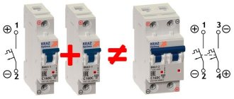
The design of a two-pole switch is identical to that of a single-pole circuit breaker. In other words, this device consists of two single-pole circuit breakers combined in one housing. Its peculiarity is that in these protective devices, in emergency situations, both protected lines are automatically switched off simultaneously. In principle, you can make a basic two-pole circuit breaker yourself by tightly connecting the control levers of two single-pole circuits with a bar.
Attention! It is impossible to replace a two-pole circuit breaker with two single switches operating separately! You should also not use single switches connected by a jumper as a two-pole circuit breaker. The design of the two-terminal circuit also includes a locking mechanism, which is not present in the “improved” device of single-pole circuit breakers.
To understand the structure and operating principle of a two-pole circuit breaker, it is enough to understand the structure of a machine with one pole. The simplest such device consists of a bimetallic plate and the design of a charging and releasing mechanism. By the way, the outdated machines looked exactly like this. The design of such a switch is shown in Figure 1.
In situations equivalent to a short circuit or during prolonged overloads in single-phase circuits, the bimetallic plate heats up and, due to deformation, acts on the operating lever of the structure. The protective shutdown mechanism is triggered and the circuit is broken.
Figure 1. Old style circuit breaker
The operating principle of this device is very simple. When the rated currents exceed the permissible parameters, the thermal release actuates the moving contact and the circuit is broken. The power cut-off mechanism can operate in two cases - during an overload or due to a short circuit. To connect the power, it is necessary to eliminate the cause of the operation currents, and then turn on the machine by pressing the control lever.
The operating scheme is simple and reliable. However, it has a significant drawback: the machine does not respond to leakage currents, therefore it cannot protect against electric shock or prevent the wiring from catching fire in the event of sparking. Additional devices are required for complete protection.
Modern two-pole packages do not have this disadvantage. Figure 2 shows the design of such a circuit breaker. Its design has one important detail - an electromagnetic release. Such two-pole devices combine the functions of conventional differential circuit breakers and a residual current device (RCD).
Figure 2. The structure of a modern machine
Thanks to the electromagnetic release, the charging and tripping mechanism of the two-pole circuit breaker reacts to leakage currents. This is the same blocking device discussed above.
Operating principle of an electromagnetic release.
Along a two-wire line, current flows in two opposite directions - along the phase conductor in one direction, and along the neutral conductor in the other. At the rated voltage, the magnetic fluxes in the solenoid coils, induced by equal counter currents, are compensated. Therefore, the resulting magnetic flux is zero.
But as soon as a leak appears, the balance is disrupted, and the resulting magnetic flux will pull the rod into the solenoid. He, in turn, will activate the levers of the cocking and release mechanism. A two-pole circuit breaker will open 2 poles, regardless of which conductor has a leak or short circuit. The RCD will trip as a reaction to changes in the parameters of the differential currents.
What is the danger of a cable mismatch with the network load?
Selecting the correct power circuit breaker is a very important task. An incorrectly selected device will not protect the line from a sudden increase in current.
But it is equally important to choose the correct cross-section of the electrical cable. Otherwise, if the total power exceeds the rated value that the conductor can withstand, this will lead to a significant increase in the temperature of the latter. As a result, the insulating layer will begin to melt, which can lead to a fire.
To more clearly imagine the consequences of a mismatch between the wiring cross-section and the total power of the devices connected to the network, let’s consider this example.
New owners, having bought an apartment in an old house, install several modern household appliances in it, giving a total load on the circuit equal to 5 kW. The current equivalent in this case will be about 23 A. In accordance with this, a 25 A circuit breaker is included in the circuit. It would seem that the choice of the circuit breaker in terms of power was made correctly, and the network is ready for operation. But some time after turning on the appliances, smoke appears in the house with a characteristic smell of burnt insulation, and after a while a flame appears. The circuit breaker will not disconnect the network from the power supply - after all, the current rating does not exceed the permissible one.
Purpose of the introductory machine
To understand why an “input circuit breaker” is needed, let’s briefly understand what a circuit breaker is in the general case and why it is needed.
An automatic protective switch is a contact switching device that is capable of disconnecting electrical networks in the event of an emergency situation (overload or short circuit).
In appearance, operating mechanism and design, the input machine is no different from a conventional protective device that controls any electrical line. The only and most important difference is its rating, which is a certain (calculated) order of magnitude higher, taking into account selectivity, than that of any linear protective switch in an electrical panel.
An input machine must be installed when introducing an electrical cable into an apartment or private house. It protects the entire electrical network of the residential premises from overload, and also serves to turn off the power to the entire facility (for example, to carry out electrical and other repair work). It also ensures the correct operation of the supply cable and does not allow the load to be exceeded for the given room.
Weak link protection
So, we are convinced that the calculation of the circuit breaker should be made based not only on the total power of the devices included in the circuit (regardless of their number), but also on the cross-section of the wires. If this indicator is not the same along the electrical line, then we select the section with the smallest cross-section and calculate the machine based on this value.
The PUE requirements state that the selected circuit breaker must provide protection for the weakest section of the electrical circuit, or have a current rating that will correspond to a similar parameter for the installations connected to the network. This also means that the connection must be made using wires with a cross-section that can withstand the total power of the connected devices.
How to select the wire cross-section and rating of the circuit breaker - in the following video:
If a careless owner ignores this rule, then in the event of an emergency that arises due to insufficient protection of the weakest section of the wiring, he should not blame the selected device and scold the manufacturer - only he himself will be to blame for the current situation.
Connection diagram for the input machine
Fundamentally, the installation and connection of the input circuit breaker is practically no different from the installation of a conventional circuit breaker. Such a machine is mounted on a DIN rail and connected before the meter (with mandatory sealing) or after. Next, the remaining circuit breakers are installed from it to protect each line of the residential premises.
How to calculate the rating of a circuit breaker?
Let's assume that we took into account all of the above and selected a new cable that meets modern requirements and has the required cross-section. Now the electrical wiring is guaranteed to withstand the load from switched on household appliances, even if there are quite a lot of them. Now we proceed directly to the selection of a circuit breaker based on current rating. Let's remember the school physics course and determine the calculated load current by substituting the corresponding values into the formula: I=P/U.
Here I is the value of the rated current, P is the total power of the installations included in the circuit (taking into account all consumers of electricity, including light bulbs), and U is the network voltage.
To simplify the selection of a circuit breaker and save you from the need to use a calculator, we present a table that shows the ratings of the circuit breakers that are included in single-phase and three-phase networks and the corresponding total load power.
This table will make it easy to determine how many kilowatts of load correspond to which rated current of the protective device. As we can see, a 25 Ampere circuit breaker in a network with a single-phase connection and a voltage of 220 V corresponds to a power of 5.5 kW, for a 32 Ampere circuit breaker in a similar network - 7.0 kW (this value is highlighted in red in the table). At the same time, for an electrical network with a three-phase delta connection and a rated voltage of 380 V, a 10 Amp circuit breaker corresponds to a total load power of 11.4 kW.
Visually about the selection of circuit breakers in the video:
Main selection criteria
In order to choose the right introductory machine (VA), you need to know what characteristics you should pay attention to when purchasing.
Rated current
This is the most important characteristic when choosing an input protective device. This property of the device indicates the maximum current, if exceeded, the power will be turned off within a certain time.
Note! Circuit breakers serve to protect the cable from overheating and the rating must be selected taking into account the cross-sectional area of the conductors!
Regardless of whether the machine is introductory or provides protection for a specific line (wire), its calculation is made based on the maximum power of electricity consumers. The rating of the input device is selected by calculating the power (or current) of all consumers when simultaneously connected to the network, for greater safety, reducing the resulting number by 10-15%, rounding down to a lower value.
Purpose
In the case of a single-circuit electrical circuit, often used in the electrification of houses, it is not advisable to use two-pole circuit breakers to protect the network. This problem is successfully solved by single-pole switches, since there is no particular need to simultaneously disconnect different segments of the circuit. In single-phase wiring with a grounded neutral, when all neutral conductors are short-circuited to neutral busbars, you can also get by with single switches.
A completely different situation arises in cases where some equipment cannot be connected to one common circuit. For example, if a transformer is used to power a group of electrical appliances, then you can’t do without a two-pole circuit breaker. The explanation is simple - there is no phase and zero at the output of the transformer. Cutting off the electric current on one of the wires does not exclude the presence of voltage on the other. Only the simultaneous disconnection of two poles ensures the safety of the equipment.
Installing a two-terminal network allows you to combine the tasks of differential protection and RCD in one device. In this case, it is no longer necessary to install separate discrete residual current devices.
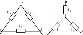
Four-pole circuit breakers operating in three-phase networks using neutral wires operate on a similar principle. Three-pole circuit breakers protect three-phase loads from short circuits.
By the way, the PUE does not prohibit the use of two-pole switches as input circuit breakers. They can also be used to protect group and individual loads. But, under no circumstances should ground wires be connected through this device. Remember that breaking the PE wire is only allowed when removing the plug from the socket.