Voltage converters are widely used both in everyday life and in production. For production and industry, they are most often made to order, because they need a powerful converter and not always with a standard voltage. Standard values for output and input parameters are often used in everyday life. That is, a voltage converter is an electronic device that is designed to change the type of electricity, its magnitude or frequency.
According to their functionality they are divided into:
- Downgrades;
- Raising;
- Transformerless;
- Inverter;
- Adjustable with adjustable frequency and output AC voltage;
- Adjustable with adjustable constant output voltage.
Some of them can be made in a special sealed design; these types of devices are used for wet rooms, or, in general, for installation under water.
So, what is each type?
High voltage voltage converter
This is an electronic device that is designed to produce alternating or direct high voltage (up to several thousand volts).
For example, such devices are used to generate high-voltage energy for television picture tubes, as well as for laboratory research and testing electrical equipment with voltages increased several times. Cables or power circuits of oil switches designed for a voltage of 6 kV are tested at a voltage of 30 kV and higher, however, this voltage value does not have high power, and in the event of a breakdown it is immediately switched off. These converters are quite compact because they have to be carried by personnel from one substation to another, most often manually. It should be noted that all laboratory power supplies and converters have almost standard, accurate voltage. Simpler high-voltage converters are used to start fluorescent lamps. The impulse can be greatly increased to the desired level using the starter and throttle, which can have an electronic or electromechanical basis.
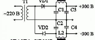
Industrial installations that convert lower voltage to high voltage have many protections and are performed using step-up transformers (STVs). Here is one of these circuits that gives an output from 8 to 16 thousand volts, while only about 50 V is needed for its operation.
Due to the fact that quite high voltage is generated and flows in the windings of transformers, high demands are placed on the insulation of these windings, as well as on its quality. In order to eliminate the possibility of corona discharges, the parts of the high-voltage rectifier must be soldered to the board carefully, without burrs and sharp corners, and then filled on both sides with epoxy resin or a layer of paraffin 2...3 mm thick, ensuring insulation from each other. Sometimes these electronic systems and devices are called step-up voltage converters.
The following circuit is a linear resonant voltage converter that operates in boost mode. It is based on the separation of functions for increasing U and its clear stabilization in completely different cascades.
At the same time, some inverter units can be made to work with minimal losses on power switches, as well as on a rectified bridge, where high-voltage voltage appears.
Features of application
At the moment, such equipment is used in almost all industries and every day it is increasingly used in the life of every person, in particular as part of the equipment of cars or trucks. The operating frequency of voltage inverters (voltage converters) does not exceed one hundred kilohertz. Plus, a voltage converter (voltage inverter) can be used as a generator. In principle, a generator and an inverter are quite similar, but you should not assume that these types of equipment are the same in purpose and operating principle.
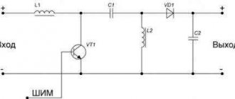
Boost converter.
There are significant differences in the generator and voltage converter circuits. In addition, compared to a diesel or gasoline generator, a voltage inverter (voltage converter) has a number of advantages, in particular:
- the voltage inverter (voltage converter) has significantly smaller dimensions and weight;
- The voltage inverter (voltage converter) does not need to constantly monitor a whole list of parameters that are mandatory when operating diesel power plants or gasoline generators. These parameters include fuel level, engine oil level and pressure, coolant temperature and level. All these parameters, for example, when operating a voltage inverter (voltage converter) from a car engine are controlled independently, in addition, with relatively low-power consumers (say, up to 1000 W), turning on the car generator for a long time is not required at all and, naturally, no fuel is consumed;
- at idle, the voltage inverter (voltage converter) has a meager energy consumption (about 5 W), in contrast to a diesel or gasoline generator, which at idle consumes up to fifty percent of the consumption at maximum load;
- absence of mechanical wear, respectively, better fault tolerance and longer service life;
- the fluctuation in the output frequency of the voltage inverter (voltage converter) is minimal and, as a rule, does not exceed hundredths of a percent;
- the voltage inverter (voltage converter) is environmentally friendly (does not make noise and does not emit exhaust gases) and allows you to connect alternative energy sources (for example, solar panels or wind generators);
- a voltage inverter (voltage converter) can be used as a starter-charger, as an uninterruptible power supply, as a battery restorer;
- and, finally, a voltage inverter (voltage converter) is simply significantly (up to several times!) cheaper.
Table - Popular models of voltage converters.
The list of potential users of voltage inverters (voltage converters) can be very wide. Here are producers of various works in remote conditions or with frequent power outages, and lovers of outdoor recreation who want to preserve the opportunity to enjoy the “benefits of civilization”, and prudent owners of various industries or protected objects, etc. and so on.
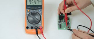
Material on the topic: Principles of operation of a multimeter and features of choice.
In particular, the use of voltage inverters (voltage converters) in conjunction with various autonomous power sources provides very big advantages; the fuel savings alone are worth it, and there is also a stored “reserve of electricity”, so to speak, just in case.
It will be interesting➡ How to choose a digital-to-analog converter (DAC)
True, when choosing voltage inverters (voltage converters), it is necessary to remember that many consumers of electric current (especially refrigerators and pumps) have a starting power several times higher than the rated power (usually, you can look at the device’s passport) and it is this that should be taken as a basis when calculating the required voltage inverter (voltage converter).
Converter 24V to 12V
Home voltage converter
Voltage converters
The average person comes across voltage converters for the home very often, because many devices have a power supply. Most often these are step-down converters that have galvanic isolation. For example, chargers for mobile phones and laptops, personal desktop computers, radios, stereo systems, various media players, and this list can be continued for a very long time, since their variety and applications in everyday life have recently been very wide.
Uninterruptible power supplies are equipped with energy storage devices in the form of batteries. Such devices are also used to maintain the operation of the heating system during an unexpected power outage. Sometimes home converters can be made according to an inverter circuit, that is, by connecting it to a direct current source (battery) powered by a chemical reaction, you can obtain a normal alternating voltage at the output, the value of which will be 220 Volts. A feature of these circuits is the ability to obtain a pure sinusoidal signal at the output.
One of the very important characteristics of converters used in everyday life is the stable signal value at the output of the device, regardless of how many volts are supplied to its input. This functional feature of power supplies is due to the fact that for stable and long-term operation of microcircuits and other semiconductor devices, a clearly standardized voltage is required, and even without ripple.
The main criteria for choosing a converter for a house or apartment are:
- Power;
- The magnitude of the input and output voltage;
- Possibility of stabilization and its limits;
- Load current value;
- Minimizing heating, that is, it is better for the converter to operate in a mode with a power reserve;
- Ventilation of the device can be natural or forced;
- Good sound insulation;
- Availability of protection against overloads and overheating.
Choosing a voltage converter is not a simple matter, because the operation of the powered device depends on the correctly selected converter.
How the device works
To convert one voltage level to another, pulse voltage converters using inductive energy storage devices are often used. According to this, three types of converter circuits are known:
- Inverting.
- Raising.
- Downgrades.
These types of converters have five elements in common:
- Key switching element.
- Power supply.
- Inductive energy storage (choke, inductor).
- A filter capacitor that is connected in parallel with the load resistance.
- Blocking diode.
The inclusion of these five elements in different combinations makes it possible to create any of the listed types of pulse converters.
Circuit of a simple voltage inverter.
Regulation of the output voltage level of the converter is ensured by changing the width of the pulses, which control the operation of the key switching element. Stabilization of the output voltage is created by the feedback method: a change in the output voltage creates an automatic change in the pulse width.
A typical representative of a voltage converter is also a transformer. It converts AC voltage of one value to AC voltage of another value. This property of a transformer is widely used in radio electronics and electrical engineering.
Table - Main characteristics of the voltage converter.
Material on the topic: What is called a trigger in electronics.
Transformerless voltage converters
Features of a voltage converter from 12V to 220V
Recently, they have become very popular, since their production, and in particular the production of transformers, requires a lot of money, because their winding is made of non-ferrous metal, the price of which is constantly growing. The main advantage of such converters is, of course, the price. Among the negative aspects, there is one thing that significantly distinguishes it from transformer power supplies and converters. As a result of a breakdown of one or more semiconductor devices, all the output energy can reach the terminals of the consumer, and this will certainly damage it. Here is the simplest AC to DC voltage converter. The role of the regulating element is played by the thyristor.
The situation is simpler with converters that do not have transformers, but operate on the basis and in the mode of a voltage-increasing device. Here, even if one or several elements fail, dangerous destructive energy will not appear on the load.
A simple homemade voltage inverter 12-220V on two transistors
As a transformer I used ferrite cups with the following dimensions: diameter - 35 mm, height - 20 mm. First, the primary winding is wound; it contains 14 turns of wire with a diameter of 0.5 mm; after winding, it must be wrapped in one layer of electrical tape. The secondary winding of the transformer is wound with a wire with a diameter of 0.2 mm and contains 220 turns; we also wrap it with electrical tape in one layer on top. That's it, the transformer is ready, all that remains is to assemble the halves and place them on the bolt.
Using trial and error, I selected transistors for the circuit, focusing on the minimum current consumption of the circuit. The result was a pair of KT814 and KT940, then the resistance and capacitance were selected. As a result of my experiments, I got the following circuit with the indicated denominations, it is shown above. This design of a simple voltage inverter is perfect for powering an energy-saving lamp with a power of 8,9,11 watts. Lamps with a power of 20 watts do not want to work, most likely the secondary is rather weak - I did not redo it. The 9-watt lamp shines as brightly as when powered directly from the 220V AC mains. The current consumption of the voltage converter circuit ranges from 0.5 – 0.54 Amperes.
Interesting read: How to easily check your computer's power supply for faults.
If you use the KT817 transistor and similar ones instead of the KT940 transistor, then the current consumed by the voltage inverter circuit and the lamp increases to 0.86 Ampere. This design of a simple voltage inverter is available for production by all radio amateurs and beginners. The advantages of this design are obvious: ease of manufacture and reliability in operation.
It should be noted that many radio amateurs live in rural areas and do not have the opportunity to purchase imported parts; moreover, although they are inexpensive, the same field-effect transistors cost money, which can immediately burn out or fail if there is an error, not to mention microcircuits. And most often, a radio amateur has limited supplies of radio components. This is how a simple voltage inverter appeared, assembled from parts obtained from Soviet trash. Having a battery with a capacity of 7 Ampere-Hours, it is not difficult to calculate how long it will last - I checked it personally.
Homemade voltage converter.
FAQ
How does the recommended charging current of up to 0.3C affect the battery plates?
For a conventional lead-acid battery, at charge currents of 0.25-0.3 C, an accelerated hydrogen evolution reaction will occur, which will lead to drying and swelling of the battery. In Carbon series batteries, as a result of the capacitive effect and an increase in the number of plates, large currents will be evenly distributed across the plates, which will prevent negative reactions due to the splitting of water in the electrolyte.
Why doesn't the voltage converter work?
Voltage converter malfunctions often occur due to the use of inappropriate wires (for example, aluminum instead of copper). Many inverter models are power sensitive. They are designed to operate only from rechargeable batteries or stabilized power sources. Such devices cannot be connected to solar panels or gas generators.
What difficulties may arise when repairing a voltage converter?
The main difficulty lies in choosing analogs of transistors and transformers in the absence of original components. The remaining elements of the electrical circuit - for example, resistors, capacitors or diodes - do not have design features, so you can use any available parts that are suitable in voltage, power and rating.
DC-DC converters
Pulse voltage converters
The AC/DC converter is the most commonly used type of device of this type. In everyday life these are all kinds of power supplies, and in production and industry these are power supply devices:
- All semiconductor circuits;
- Excitation windings of synchronous motors and DC motors;
- Oil switch solenoid coils;
- Operating and tripping circuits where coils require constant current.
A thyristor voltage converter is the most commonly used device for these purposes. A feature of these devices is the complete, rather than partial, conversion of alternating voltage to direct voltage without any kind of ripple. A powerful voltage converter of this type must necessarily include radiators and fans for cooling, since all electronic parts can operate for a long time and trouble-free only at operating temperatures.
Operating principle
The voltage converter generates the supply voltage of the required value from another supply voltage, for example, to power certain equipment from a battery. One of the main requirements for the converter is to ensure maximum efficiency. Conversion of alternating voltage can be easily accomplished using a transformer, as a result of which such direct voltage converters are often created on the basis of an intermediate conversion of direct voltage to alternating voltage.
- A powerful alternating voltage generator, which is powered by an original direct voltage source, is connected to the primary winding of the transformer.
- An alternating voltage of the required magnitude is removed from the secondary winding, which is then rectified.
- If necessary, the constant output voltage of the rectifier is stabilized using a stabilizer, which is switched on at the output of the rectifier, or by controlling the parameters of the alternating voltage generated by the generator.
- To achieve high efficiency, voltage converters use generators that operate in switching mode and generate voltage using logic circuits.
- The output transistors of the generator, which switch the voltage on the primary winding, go from a closed state (no current flows through the transistor) to a saturation state, where the voltage across the transistor drops.
- In voltage converters of high-voltage power supplies, in most cases, self-inductive emf is used, which is created at the inductance in cases of sudden interruption of the current. A transistor acts as a current interrupter, and the primary winding of the step-up transformer acts as an inductance. The output voltage is created on the secondary winding and rectified. Such circuits are capable of generating voltages up to several tens of kV. They are often used to power cathode ray tubes, picture tubes, and so on. This ensures efficiency above 80%.
Schematic diagram of a transformerless voltage converter.
Adjustable voltage converter
These devices are designed to operate in both voltage increase and decrease modes. Most often, these are still devices that smoothly adjust the value of the output signal, which is lower than the input signal. That is, 220 Volts are supplied to the input, and at the output we get an adjustable constant value, say, from 2 to 30 volts. Such devices with very fine adjustment are used to test pointer and digital instruments in laboratories. It is very convenient when they are equipped with a digital indicator. It must be admitted that every radio amateur took this type as the basis for his first work, since the power supply for certain equipment can be different in size, but this power source turned out to be very universal. How to make a high-quality converter that works for a long time is the main problem of young radio amateurs.
Additional materials:
Articles:
- Maxim Integrated nanoPower Technology: When Low IQ Benefits
- Sleep Control: Improve Battery Efficiency with DC/DC MAX17225 nanoPower
- One choke for the entire system: Maxim multichannel converters with SIMO and nanoPower technologies
- Real-time power measurement using power logger IC
- Extending the runtime of portable electronics with a SIMO-based converter
- SIMO fighters: features of using Maxim SIMO converters
- Selecting a SIMO PMIC Converter for a Handheld Device Project
- Increasing the energy efficiency of portable devices using SIMO PMIC converters
News
- MAX17222 - long life for small things
- MAX38640/1/2/3 – step-down converters of the NanoPower family with ultra-low current consumption
- MAX17270 – NanoPower SIMO PMIC for IoT with ultra-low power consumption
•••
Inverter voltage converter
This type of converter forms the basis for innovative compact welding devices. Receiving an alternating voltage of 220 volts for power supply, the device rectifies it, after which it again makes it alternating, but with a frequency of several tens of thousands of Hz. This makes it possible to significantly reduce the dimensions of the welding transformer installed at the output.
The inverter method is also used to power heating boilers from batteries in the event of an unexpected power outage. Due to this, the system continues to operate and receives 220 volts of alternating voltage from 12 volts of direct voltage. A powerful booster device for this purpose must be operated from a large-capacity battery; this determines how long it will supply the boiler with electricity. That is, capacity plays a key role.
Notes
- ↑ S. Yu. Zabrodin
Chapter 5 Low-power DC rectifiers, §5.1 General information // Industrial electronics: textbook for universities. - M.: Higher School, 1982. - P. 287. - 496 p. - ↑ S. Yu. Zabrodin
Chapter 6 Network-driven converters of medium and high power, §6.1 general information // Industrial electronics: textbook for universities. - M.: Higher School, 1982. - P. 315. - 496 p. - ↑ S. Yu. Zabrodin
Chapter 8 Autonomous inverters, §8.1 Autonomous inverters and their classification // Industrial electronics: textbook for universities. - M.: Higher School, 1982. - P. 438. - 496 p.
Wikimedia Foundation. 2010.
Useful
See what “Electric energy converter” is in other dictionaries:
electrical energy converter - An electrical product (device) that converts electrical energy with one value of parameters and (or) quality indicators into electrical energy with other values of parameters and (or) quality indicators. Note... ... Technical Translator's Handbook
Electrical energy converter - 4. Electrical energy converter Converter Electrical energy converter An electrical product (device) that converts electrical energy with the same values of parameters and (or) quality indicators into electrical energy with... ... Dictionary of terms of normative and technical documentation
electrical energy converter, - 2 electrical energy converter, electrical energy converter: An electrical device that converts electrical energy with one value of parameters and/or quality indicators into electrical energy with other values... ... Dictionary of terms of normative and technical documentation
Electrical energy converter is an electrical product (device) that converts electrical energy with one value of parameters and (or) quality indicators into electrical energy with other values of parameters and (or) quality indicators. GOST 18311 80 ... Commercial electric power industry. Dictionary-reference book
Electrical energy converter - 1. An electrical product (device) that converts electrical energy with one value of parameters and (or) quality indicators into electrical energy with other values of parameters and (or) quality indicators. Used in ... ... Telecommunications Dictionary
Electrical energy converter (Electricity converter) - English: Electricity converter An electrical product (device) that converts electrical energy with one values of parameters and (or) quality indicators into electrical energy with other values of parameters and (or) indicators... ... Construction Dictionary
GOST R 54130-2010: Quality of electrical energy. Terms and definitions - Terminology GOST R 54130 2010: Quality of electrical energy. Terms and definitions original document: Amplitude die schnelle VergroRerung der Spannung 87 Definitions of the term from various documents: Amplitude die schnelle VergroRerung der... ... Dictionary-reference book of terms of normative and technical documentation
PLASMA SOURCES OF ELECTRICAL ENERGY - converters of plasma thermal energy into electricity. energy. There are two types of P. and. e. e. magnetohydrodynamic generator and thermionic converter. Physical encyclopedic dictionary. M.: Soviet Encyclopedia. Editor-in-Chief...Physical Encyclopedia
Plasma sources of electrical energy are converters of thermal energy of plasma (See Plasma) into electrical energy. There are 2 types of P. and. e. e. Magnetohydrodynamic generator and thermionic converter ... Great Soviet Encyclopedia
frequency converter - frequency converter AC electrical energy converter that converts electrical energy with a change in frequency [OST 45.55 99] EN frequency converter electric energy... ... Technical Translator's Guide
Source
High frequency voltage converter
Due to the use of boost converters, it becomes possible to reduce the size of all electronic and electromagnetic elements that make up the circuits, which means the cost of transformers, coils, capacitors, etc. is reduced. However, this can cause high-frequency radio interference, which affects the operation of other electronic devices. systems, and even ordinary radio receivers, so their housings need to be reliably shielded. The calculation of the converter and its interference must be carried out by highly qualified personnel.
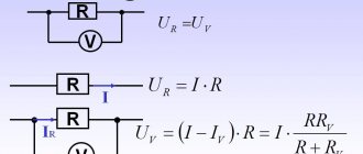
What is a resistance to voltage converter? This is a special type that is used only in the production and manufacture of measuring instruments, in particular ohmmeters. After all, the basis of an ohmmeter, that is, a device that measures resistance, is made in measuring the drop in U and converting it into pointer or digital indicators. Typically measurements are made relative to direct current. A measuring transducer is a technical device used to convert a measured value into another value or a measuring signal, convenient for processing, storage, further transformations, indication, and transmission. It is part of any measuring device.
Advantages and disadvantages
The advantages of voltage converters include:
- the ability to control the parameters of the output signal - converting its variable value into a constant value using the principle of frequency conversion;
- availability of an option for switching input and output circuits (varying voltage amplitude);
- the permissibility of adjusting their nominal values for a specific load;
- compactness and simplicity of design of household converters, which are often manufactured in modular or wall-mounted versions;
- efficiency (according to manufacturers, their efficiency reaches 90%);
- ease of use and versatility;
- the possibility of transmitting electricity over remote distances and ensuring the operation of particularly critical industries.
The disadvantages include high cost and low moisture resistance (with the exception of models designed specifically for operation in conditions of high humidity).
Current to voltage converter
In most cases, all electronic circuits are needed to process signals represented in the form of voltage. However, sometimes you have to deal with a signal in the form of current. Such signals arise, for example, at the output of a photoresistor or photodiode. Then it is advisable to convert the current signal into voltage at the first opportunity. Voltage-to-current converters are used when the current in the load must be proportional to the input U and independent of the R load. In particular, with a constant input U, the current in the load will also be constant, therefore such converters are sometimes conventionally called current stabilizers.
Classification
By the nature of the transformation
Rectifiers
A rectifier is a device designed to convert the energy of an alternating current source into direct current. [1]
Inverters
Inverter
- a device whose task is the opposite of a rectifier, that is, converting the energy of a direct current source into alternating current energy.
Inverters are divided into two classes: grid driven
(dependent) and
autonomous
.
Dependent inverters
Slave inverters
convert the energy of a direct current source into alternating current and release it into the alternating current network, that is, they carry out the conversion inverse to the rectifier. [2]
Autonomous inverters
Autonomous inverters
- devices that convert direct current into alternating current with a constant or adjustable frequency and operate on an autonomous (not connected to the alternating current network) load. [3]
In turn, autonomous inverters are divided into:
Frequency converters
Switching voltage converters
By control method
By type of schemes
By control method
Voltage converter repair
Repair of these devices to convert one type of voltage to another is best done in service centers, where the personnel are highly qualified and will subsequently provide guarantees for the work performed. Most often, any modern high-quality converters consist of several hundred electronic parts, and if there are no obvious burnt elements, then it will be very difficult to find a breakdown and fix it. Some Chinese inexpensive devices of this type, in general, are in principle deprived of the possibility of repairing them, which cannot be said about domestic manufacturers. Yes, they may be a little bulky and not compact, but they can be repaired, since many of their parts can be replaced with similar ones.
History of development
At the beginning of the practical use of electrical energy (1880s), the problem of energy conversion arose.
| Period of use | Component base | Peculiarities |
| 1880s | Motor generator | + Pure sine wave + High efficiency + High power - Material consumption - Difficulty in repair and maintenance - Noise and vibration |
| 1880s Currently in use | Transformers | + Greater reliability + High efficiency + High power - Large dimensions at low frequencies - Impossibility of DC conversion |
| 1930-1970s Currently practically not used | Ionic devices | — Fragility of cases (glass) — Long preparation time for work |
| 1960s Currently in use | Semiconductor diodes, thyristors | + Compactness + Quietness + Ease and flexibility of control - Power losses in switches - Distortion and interference in networks |
Often the appearance of new devices does not eliminate the need to use a number of previously existing devices. For example, many semiconductor devices use transformers, but in the more advantageous high-frequency range. As a result, the device acquires the advantages of both. The use of p-p inverters to control umformers makes it possible to eliminate commutators and brushes. This reduces ohmic and friction losses. The inverters themselves can also be of lower power, for example, when using dual-power machines, the losses are lower, and the quality of energy conversion is much higher.
