Single-phase asynchronous motors are powered from a conventional 220 V alternating voltage network.
The most common design of such motors contains two (or more) windings - working and phase-shifting. The working one is fed directly, and the additional one is fed through a capacitor, which shifts the phase by 90 degrees, which creates a rotating magnetic field. Therefore, such motors are also called two-phase or capacitor motors.
It is necessary to regulate the rotation speed of such motors, for example, for:
- changes in air flow in the ventilation system
- pump performance control
- changes in the speed of moving parts, for example in machine tools, conveyors
In ventilation systems, this allows you to save energy, reduce the level of acoustic noise of the installation, and set the required performance.
Methods of regulation
We will not consider mechanical methods of changing the rotation speed, for example gearboxes, couplings, gear transmissions. We will also not touch upon the method of changing the number of poles of the windings.
Let's consider methods with changing electrical parameters:
- change in motor supply voltage
- change in supply voltage frequency
Three-phase
Such electric motors are mostly used in production. The principle of operation is determined by its design - with a wound or squirrel-cage rotor. To start it, you do not need a starting winding, capacitor or other devices. The starting current and power are quite high. It is used in machine tools, pumps, and agricultural machinery.
- closed – make up 90% of all electric motors. There are different powers from 250 W;
- phase - their devices and operating principle differ from a three-phase electric motor.
Selection criteria and cost
In order to correctly choose the most suitable type of regulator, you need to have a good idea of what types of such devices there are:
- Various types of control. Can be a vector or scalar control system. The former are used more often, while the latter are considered more reliable.
- The power of the regulator must correspond to the maximum possible power of the motor.
- Based on voltage, it is convenient to choose a device that has the most universal properties.
- Frequency characteristics. The regulator that suits you should match the highest frequency that the motor uses.
- Other characteristics. Here we are talking about the length of the warranty period, dimensions and other characteristics.
Depending on the purpose and consumer properties, prices for regulators can vary significantly.
For the most part, they range from approximately 3.5 thousand rubles to 9 thousand:
- Speed controller KA-18 ESC , designed for 1:10 scale models. Costs 6890 rubles.
- MEGA speed controller is manifold (waterproof). Costs 3605 rubles.
- Speed controller for LaTrax 1:18 models. Its price is 5690 rubles.
The engine speed controller is needed to perform smooth acceleration and braking. Such devices have become widespread in modern industry. Thanks to them, the speed of movement in the conveyor, on various devices, as well as when the fan rotates, is measured. Motors with 12 Volt performance are used in entire control systems and in cars.
Method of operation and number of revolutions of the blood pressure
The main parts of an asynchronous motor are the rotor and stator. The voltage that is transmitted to the starter winding forms magnetic fluxes. They are deflected geometrically by 1200C.
The magnetic field and current in the windings form an electromagnetic flux, which causes the rotor to spin. In addition, an EMF occurs in the rotor conductors. A current appears in the closed electrical circuit of the rotor winding, which interacts with the magnetic field of the starter. As a result, a moment is created when the rotor begins to rotate.
Source: motorstory.ru
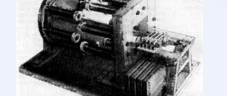
A little theory about the design and scope of commutator electric motors
Electric motors of this type can be direct or alternating current, with series, parallel or mixed excitation (for alternating current only the first two types of excitation are used).
A commutator motor consists of a rotor, stator, commutator and brushes. The current in the circuit passing through the stator and rotor windings connected in a certain way creates a magnetic field that causes the latter to rotate. Voltage is transmitted to the rotor using brushes made of a soft electrically conductive material, most often graphite or a copper-graphite mixture. If you change the direction of the current in the rotor or stator, the shaft will begin to rotate in the other direction, and this is always done with the rotor leads, so that the magnetization reversal of the cores does not occur.
Types of engines
The speed control with power maintenance is an invention that will breathe new life into an electrical appliance, and it will work like a newly purchased product . But it is worth remembering that engines come in different formats and each has its own maximum performance.
The engines have different characteristics. This means that this or that technique operates at different speeds of the shaft that triggers the mechanism. The motor can be :
Mostly three-phase electric motors are found in factories or large factories. At home, single-phase and two-phase are used. This electricity is enough to operate household appliances.
Adjustment
Now let's talk about how you can regulate the speed of commutator motors. Due to the fact that the rotation speed of the motor simply depends on the amount of voltage supplied, any means of adjustment that are capable of performing this function are quite suitable for this.
Let's list a few of these options as examples:
- Laboratory autotransformer (LATR).
- Factory control boards used in household appliances (you can use, in particular, those used in mixers or vacuum cleaners).
- Buttons used in the design of power tools.
- Household lighting regulators with smooth action.
However, all of the above methods have a very important flaw. Along with the decrease in speed, the engine power also decreases. In some cases, it can be stopped even just with your hand. In some cases, this may be acceptable, but in most cases, it is a serious obstacle.
A good option is to adjust the speed using a tachogenerator. It is usually installed at the factory. If there are deviations in the motor rotation speed, an already adjusted power supply corresponding to the required rotation speed is transmitted through the triacs to the motor. If you integrate motor rotation control into this circuit, then there will be no loss of power.
How does this look constructively? The most common are rheostatic rotation control, and those made using semiconductors.
In the first case, we are talking about variable resistance with mechanical adjustment. It is connected in series to the commutator motor. The disadvantage is the additional heat generation and additional waste of battery life. With this adjustment method, there is a loss of engine rotation power. Is a cheap solution. Not applicable for sufficiently powerful motors for the reasons mentioned.
In the second case, when using semiconductors, the motor is controlled by applying certain pulses. The circuit can change the duration of such pulses, which in turn changes the rotation speed without loss of power.
Power speed regulator
Work principles
A 220 V electric motor speed controller without loss of power is used to maintain the initial set shaft speed. This is one of the basic principles of this device, which is called a frequency regulator.
With its help, the electrical device operates at the set engine speed and does not reduce it . The engine speed controller also affects the cooling and ventilation of the motor. With the help of power, the speed is set, which can be either raised or reduced.
Many people have asked the question of how to reduce the speed of a 220 V electric motor. But this procedure is quite simple. One has only to change the frequency of the supply voltage, which will significantly reduce the performance of the motor shaft. You can also change the power supply to the motor by activating its coils. Electrical control is closely related to the magnetic field and motor slip. For such actions, they mainly use an autotransformer and household regulators, which reduce the speed of this mechanism. But it is also worth remembering that engine power will decrease.
Shaft rotation
Engines are divided into:
The speed controller of an asynchronous electric motor depends on the current connection to the mechanism. The essence of the operation of an asynchronous motor depends on the magnetic coils through which the frame passes. It rotates on sliding contacts. And when, when turning, it turns 180 degrees, then through these contacts the connection will flow in the opposite direction. This way the rotation will remain the same. But with this action the desired effect will not be obtained. It will come into force after a couple of dozen frames of this type are added to the mechanism.
The commutator motor is used very often . Its operation is simple, since the transmitted current passes directly - because of this, the power of the electric motor is not lost, and the mechanism consumes less electricity.
The washing machine motor also needs power adjustment. For this purpose, special boards were made that cope with their job: the engine speed control board from a washing machine has multifunctional use, since its use reduces the voltage, but does not lose rotation power.
The circuit of this board has been verified. All you have to do is install diode bridges and select an optocoupler for the LED. In this case, you still need to put a triac on the radiator. Basically, engine adjustment starts at 1000 rpm.
If you are not satisfied with the power regulator and its functionality is lacking, you can make or improve the mechanism . To do this, you need to take into account the current strength, which should not exceed 70 A, and heat transfer during use. Therefore, an ammeter can be installed to adjust the circuit. The frequency will be small and will be determined by capacitor C2.
Next, you should configure the regulator and its frequency. When outputting, this pulse will go out through a push-pull amplifier using transistors. You can also make 2 resistors that will serve as an output for the computer's cooling system. To prevent the circuit from burning out, a special blocker is required, which will serve as double the current value. So this mechanism will work for a long time and in the required volume. Power regulating devices will provide your electrical appliances with many years of service without special costs.
Source: instrument.guru
Single channel motor controller
The device controls one motor, powered by voltage in the range from 2 to 12 volts.
Device design
The main design elements of the regulator are shown in the photo. 3. The device consists of five components: two variable resistance resistors with a resistance of 10 kOhm (No. 1) and 1 kOhm (No. 2), a transistor model KT815A (No. 3), a pair of two-section screw terminal blocks for the output for connecting a motor (No. 4) and input for connecting a battery (No. 5).
Note 1: Installation of screw terminal blocks is optional. Using a thin stranded mounting wire, you can connect the motor and power source directly.
Principle of operation
The operating procedure of the motor controller is described in the electrical diagram (Fig. 1). Taking into account the polarity, a constant voltage is supplied to the XT1 connector. The light bulb or motor is connected to the XT2 connector. A variable resistor R1 is turned on at the input; rotating its knob changes the potential at the middle output as opposed to the minus of the battery. Through current limiter R2, the middle output is connected to the base terminal of transistor VT1. In this case, the transistor is switched on according to a regular current circuit. The positive potential at the base output increases as the middle output moves upward from the smooth rotation of the variable resistor knob. There is an increase in current, which is due to a decrease in the resistance of the collector-emitter junction in transistor VT1. The potential will decrease if the situation is reversed.
Read also: Dimensions of gas cylinders for cars table
Electrical circuit diagram
Materials and details
A printed circuit board measuring 20x30 mm is required, made of a fiberglass sheet foiled on one side (permissible thickness 1-1.5 mm). Table 1 provides a list of radio components.
Note 2. The variable resistor required for the device can be of any manufacture; it is important to comply with the current resistance values for it indicated in Table 1.
Note 3 . To regulate currents above 1.5A, the KT815G transistor is replaced with a more powerful KT972A (with a maximum current of 4A). In this case, the printed circuit board design does not need to be changed, since the distribution of pins for both transistors is identical.
Build process
For further work, you need to download the archive file located at the end of the article, unzip it and print it. The regulator drawing (termo1 file) is printed on glossy paper, and the installation drawing (montag1 file) is printed on a white office sheet (A4 format).
Next, the drawing of the circuit board (No. 1 in photo. 4) is glued to the current-carrying tracks on the opposite side of the printed circuit board (No. 2 in photo. 4). It is necessary to make holes (No. 3 in photo. 14) on the installation drawing in the mounting locations. The installation drawing is attached to the printed circuit board with dry glue, and the holes must match. Photo 5 shows the pinout of the KT815 transistor.
The input and output of terminal blocks-connectors are marked white. A voltage source is connected to the terminal block via a clip. A fully assembled single-channel regulator is shown in the photo. The power source (9 volt battery) is connected at the final stage of assembly. Now you can adjust the shaft rotation speed using the motor; to do this, you need to smoothly rotate the variable resistor adjustment knob.
To test the device, you need to print a disk drawing from the archive. Next, you need to paste this drawing (No. 1) onto thick and thin cardboard paper (No. 2). Then, using scissors, a disc is cut out (No. 3).
The resulting workpiece is turned over (No. 1) and a square of black electrical tape (No. 2) is attached to the center for better adhesion of the surface of the motor shaft to the disk. You need to make a hole (No. 3) as shown in the image. Then the disk is installed on the motor shaft and testing can begin. The single-channel motor controller is ready!
Rotation speed control of single-phase motors
Single-phase asynchronous motors are powered from a conventional 220 V alternating voltage network.
The most common design of such motors contains two (or more) windings - working and phase-shifting. The working one is fed directly, and the additional one is fed through a capacitor, which shifts the phase by 90 degrees, which creates a rotating magnetic field. Therefore, such motors are also called two-phase or capacitor motors.
It is necessary to regulate the rotation speed of such motors, for example, for:
- changes in air flow in the ventilation system
- pump performance control
- changes in the speed of moving parts, for example in machine tools, conveyors
In ventilation systems, this allows you to save energy, reduce the level of acoustic noise of the installation, and set the required performance.
Methods of regulation
We will not consider mechanical methods of changing the rotation speed, for example gearboxes, couplings, gear transmissions. We will also not touch upon the method of changing the number of poles of the windings.
Let's consider methods with changing electrical parameters:
- change in motor supply voltage
- change in supply voltage frequency
Ways to change engine speed
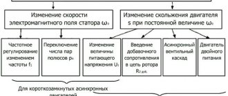
Adjusting the speed of any three-phase electric motor used in lifting and transport machinery and equipment allows you to achieve the required operating modes accurately and smoothly, which is not always possible, for example, due to mechanical gearboxes. In practice, seven main methods of rotation speed correction are used, which are divided into two key areas:
- Change in the speed of the magnetic field in the stator. Achieved by frequency regulation, switching the number of pole pairs or voltage correction. It should be added that these methods are applicable to electric motors with squirrel-cage rotor;
- Changing the amount of slip. This parameter can be adjusted by using the supply voltage, connecting additional resistance to the electrical circuit of the rotor, using a valve cascade or dual power supply. Used for models with wound rotor.
The most popular methods are voltage and frequency regulation (through the use of converters), as well as changing the number of pole pairs (implemented by organizing an additional winding with switching capability).
Voltage regulation
Speed control in this way is associated with a change in the so-called engine slip - the difference between the rotation speed of the magnetic field created by the stationary engine stator and its moving rotor:
n1— magnetic field rotation speed
n2 — rotor rotation speed
In this case, sliding energy is necessarily released - which causes the motor windings to heat up more.
This method has a small control range, approximately 2:1, and can also only be carried out downwards - that is, by reducing the supply voltage.
When regulating speed in this way, it is necessary to install oversized motors.
But despite this, this method is used quite often for low-power motors with a fan load.
In practice, various regulator circuits are used for this.
Autotransformer voltage regulation
An autotransformer is an ordinary transformer, but with one winding and taps from some of the turns. In this case, there is no galvanic isolation from the network, but in this case it is not needed, so savings are achieved due to the absence of a secondary winding.
Frequency regulation
Just recently (10 years ago), there were a limited number of frequency controllers for motor speeds on the market, and they were quite expensive. The reason was that there were no cheap high-voltage power transistors and modules.
But developments in the field of solid-state electronics have made it possible to bring power IGBT modules to the market. As a consequence, there is a massive appearance on the market of inverter air conditioners, welding inverters, and frequency converters.
At the moment, frequency conversion is the main way to regulate the power, performance, speed of all devices and mechanisms driven by an electric motor.
However, frequency converters are designed to control three-phase electric motors.
Single-phase motors can be controlled by:
- specialized single-phase inverters
- three-phase inverters with the exception of the capacitor
Converters for single-phase motors
Currently, only one manufacturer announces serial production of a specialized inverter for capacitor motors - INVERTEK DRIVES.
Optidrive E2 model
For stable engine starting and operation, special algorithms are used.
In this case, frequency adjustment is possible upward, but in a limited frequency range, this is prevented by a capacitor installed in the phase-shifting winding circuit, since its resistance directly depends on the frequency of the current:
f - current frequency
C - capacitance of the capacitor
The output stage uses a bridge circuit with four output IGBT transistors:
Optidrive E2 allows you to control the motor without removing the capacitor from the circuit, that is, without changing the motor design - in some models this is quite difficult to do.
Advantages of a specialized frequency converter:
- intelligent motor control
- Stably stable engine operation
- the enormous capabilities of modern inverters: the ability to control the operation of the motor to maintain certain characteristics (water pressure, air flow, speed under changing load)
- numerous protections (motor and device itself)
- sensor inputs (digital and analogue)
- various outputs
- communication interface (for control, monitoring)
- preset speeds
- PID controller
Disadvantages of using a single-phase inverter:
Using a state of emergency for three-phase motors
A standard frequency converter has a three-phase voltage at its output. When connecting a single-phase motor to it, remove the capacitor from it and connect it according to the diagram below:
The geometric arrangement of the windings relative to each other in the stator of an asynchronous motor is 90°:
The phase shift of the three-phase voltage is -120°, as a consequence of this - the magnetic field will not be circular, but pulsating and its level will be less than with a power supply with a shift of 90°.
In some capacitor motors, the additional winding is made of thinner wire and therefore has a higher resistance.
When operating without a capacitor, this will lead to:
- stronger heating of the winding (service life is reduced, short circuits and interturn short circuits are possible)
- different current in the windings
Many inverters have protection against current asymmetry in the windings; if it is impossible to disable this function in the device, operation using this circuit will be impossible
Advantages:
- lower cost compared to specialized inverters
- Huge selection of power and manufacturers
- wider frequency control range
- all the advantages of the inverter (inputs/outputs, intelligent operating algorithms, communication interfaces)
Disadvantages of the method:
- the need for preliminary selection of the inverter and motor for joint operation
- pulsating and reduced torque
- increased heating
- no warranty in case of failure, because Three-phase inverters are not designed to work with single-phase motors
Source: masterxoloda.ru
How to make it yourself?
There are various options for adjustment schemes. Let us present one of them in more detail.
Here is how it works:
Initially, this device was developed to adjust the commutator motor in electric vehicles. We were talking about one where the supply voltage is 24 V, but this design is also applicable to other engines.
The weak point of the circuit, which was identified during testing of its operation, is its poor suitability at very high current values. This is due to some slowdown in the operation of the transistor elements of the circuit.
It is recommended that the current be no more than 70 A. There is no current or temperature protection in this circuit, so it is recommended to build in an ammeter and monitor the current visually. The switching frequency will be 5 kHz, it is determined by capacitor C2 with a capacity of 20 nf.
At the same time, it is recommended to select the value of R1 in such a way as to correctly configure the operation of the regulator. From the output of the microcircuit, the control pulse goes to a push-pull amplifier using transistors KT815 and KT816, and then goes to the transistors.
The printed circuit board has a size of 50 by 50 mm and is made of single-sided fiberglass:
This diagram additionally shows 2 45 ohm resistors. This is done for the possible connection of a regular computer fan to cool the device. When using an electric motor as a load, it is necessary to block the circuit with a blocking (damper) diode, which in its characteristics corresponds to twice the load current and twice the supply voltage.
Read also: Pattern for weaving a beaded bracelet for beginners
Operating the device in the absence of such a diode may lead to failure due to possible overheating. In this case, the diode will need to be placed on the heat sink. To do this, you can use a metal plate that has an area of 30 cm2.
Regulating switches work in such a way that the power losses on them are quite small. In the original design, a standard computer fan was used. To connect it, a limiting resistance of 100 Ohms and a supply voltage of 24 V were used.
The assembled device looks like this:
When manufacturing a power unit (in the lower figure), the wires must be connected in such a way that there is a minimum of bending of those conductors through which large currents pass. We see that the manufacture of such a device requires certain professional knowledge and skills. Perhaps in some cases it makes sense to use a purchased device.
Adjustment of electric motor speed 220V and 12V
Some situations require changing the engine speed from the nominal speed. Sometimes it is necessary to reduce the speed of the electric motor, because increasing it negatively affects the bearing system. The methods for changing rotation depend on the model of the electric machine.
The characteristics of electrical machines are different: direct and alternating current, single-phase, three-phase. Therefore, we need to talk about each case separately.
- The simplest option
- In armature circuit For low voltage
- Collector machines
Regulators for generator set engines
Classes 1, 2 and 3 can operate with mechanical regulators. Electronic governors are typically used for Class 4, which also includes generator sets with 0% speed reduction.
The characteristic curves of regulators for generator sets are shown in the figure. To ensure that no parallel operation is required, generators can be operated at a fixed speed, allowing the use of simple maximum speed controls.
Rice. Regulators for generator set engines: 1. Control rack stroke; 2. Overload; 3. Full load; 4. Adjustment area; 5. No load; 6. Engine speed.
Table. Types of regulators
| Designation | Type | Revolution registration mechanism | Fuel pump size | Torque control |
| RQ | Minimum and maximum speed regulator or maximum speed regulator only | Centrifugal weights | A,MW,P | Positive (principled) |
| RQ | Generator Set Regulator | Centrifugal weights | A,MW,P | Absent |
| RQU | Minimum and maximum speed regulator or maximum speed regulator only | Centrifugal weights | ZW,P9,P10 | Forced |
| R.S. | Minimum and maximum speed regulator | Centrifugal weights | A,MW,P | Forced |
| RSF | Minimum and maximum speed regulator | Centrifugal weights | M | Negative/ Positive |
| RQV | Speed changer or combined regulator | Centrifugal weights | A,MW,P | Positive |
| RQUV | Speed change regulator | Centrifugal weights | ZW,P9,P10 | Positive |
| RQV…K | Speed change regulator | Centrifugal weights | A,MW,P | Negative/ Positive |
| RSV | Speed change regulator | Centrifugal weights | A,MW,P | Positive |
| RSUV | Speed change regulator | Gear-fed centrifugal weights for low-speed engines | P | Positive |
| RE | Arbitrary controller characteristic curves | Solenoid | M,MW,P | Negative/ Positive |
The simplest option
The easiest way is to change the speed of a DC motor. They can be changed by simply changing the supply voltage. And it doesn’t matter where: at anchor or excited, but this only applies to low-power machines with minimal load. Basically, the rotation speed is controlled via the armature circuit. Moreover, rheostatic regulation is possible here if the motor power is small, or there is a fairly powerful rheostat.
This is the most uneconomical option. The mechanical characteristics of a motor with independent excitation are the most unfavorable due to large losses, which results in a drop in mechanical power and efficiency.
Another possibility is to introduce a rheostat into the field winding. Considering the characteristics of an engine with independent excitation, we will see that regulation of the rotation speed is possible only in the direction of increasing revolutions. This occurs due to winding saturation.
In the anchor chain
This is the best option for regulating the speed of a motor with independent excitation. The rotation speed is directly proportional to the voltage supplied to the armature. The mechanical characteristics do not change their angle of inclination, but move parallel to each other.
To implement this scheme, you need to connect the armature circuit to a voltage source that can be changed.
This is possible in low or medium power electric machines. It is advisable to connect a high-power motor to a circuit with an independent excitation voltage generator.
A conventional three-phase asynchronous machine is used as a drive for the generator. To reduce the speed, it is enough to lower the voltage at the armature. It varies from nominal and down. This circuit is called “motor-generator”. This way you can change the parameters on a 220V engine.
For low voltage
Controlling 12V units is easier due to the lower voltage and, as a result, more accessible parts. There are many options for such schemes, so it is important to understand the principle itself.
Such a motor has a rotor, a brush mechanism and magnets. It has only two wires at the output; speed is controlled through them. The power supply can be 12, 24, 36V, or other. What is needed is to change it. It's better when it ranges from zero to maximum. In simpler options, 12–0V will not work; other options provide this opportunity.
Some solder radioelements using surface mounting, others assemble a printed circuit board - it depends on the desires and capabilities of each person.
This option is suitable if accuracy is not important: for example, a fan. The voltage varies from 0 to 12 volts, and the torque changes proportionally.
Another option is with stabilization of speed regardless of the load on the shaft.
The power supply is 12 volts, the circuit is very simple. The engine picks up speed smoothly and also smoothly reduces it as the output voltage varies within 12–0V. As a result, the torque can be reduced to almost zero. If the potentiometer is turned in the opposite direction, the motor also gradually gains speed to maximum. The microcircuit is very common, its characteristics are also described in detail. Power supply 12–18c.
There is another option, only this is not for 12, but for 24V power supply.
The motor is DC, the power supply is AC, as there is a diode bridge. If desired, you can throw away the bridge and power it with constant voltage from your power supply.
Single-phase AC motors also allow you to control the rotation of the rotor.
Collector machines
Such motors are found on electric drills, jigsaws and other tools. To reduce or increase the speed, it is enough, as in previous cases, to change the supply voltage. There are also solutions for this purpose.
The structure connects directly to the network. The adjusting element is a triac, which is controlled by a dinistor. The triac is placed on the heat sink, the maximum load power is 600 W.
If there is a suitable LATR, you can do all this using it.
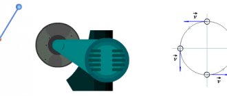
Two phase motor
The device, which has two windings - starting and working, is two-phase in principle. Unlike three-phase, it has the ability to change the rotor speed. The characteristic of its rotating magnetic field is not circular, but elliptical, which is due to its design.
There are two possibilities for controlling the speed:
- Change the amplitude of the supply voltage (Uy);
- Phase - change the capacitance of the capacitor.
Such units are widely used in everyday life and in production.
Regular asynchronous
Three-phase electric machines, despite their ease of operation, have a number of characteristics that need to be taken into account. If you simply change the supply voltage, the torque will change within a small range, but no more. In order to regulate speed within a wide range, you need quite complex equipment, which is difficult and expensive to simply assemble and set up.
For this purpose, the industry has launched the production of frequency converters that help change the speed of the electric motor in the desired range.
The asynchronous machine gains momentum in accordance with the parameters set on the frequency driver, which can be changed in a wide range. The converter is the best solution for such engines.
It is clear that the number of revolutions needs to be determined somehow. Tachometers are used for this. They show the rotation number at the moment. You can’t simply measure speed with a regular multimeter, except in a car.
As you can see, on electric machines you can change various parameters, adjusting them to the needs of production and household use.
Source: electricvdele.ru
Converters on electronic keys
Common thyristor regulators with a simple operating circuit.
Thyristor, works in alternating current network.
A separate type is the AC voltage stabilizer. The stabilizer contains a transformer with numerous windings.
DC stabilizer circuit
24 volt thyristor charger
To a 24 volt voltage source. The principle of operation is to charge a capacitor and a locked thyristor, and when the capacitor reaches voltage, the thyristor sends current to the load.
Proportional Signal Process
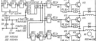
Signals arriving at the system input form feedback. Let's take a closer look using a microcircuit.
Chip TDA 1085
The TDA 1085 chip pictured above provides feedback control of a 12V, 24V motor without loss of power. It is mandatory to contain a tachometer, which provides feedback from the engine to the control board. The stabilization sensor signal goes to a microcircuit, which transmits the task to the power elements - to add voltage to the motor. When the shaft is loaded, the board increases the voltage and the power increases. By releasing the shaft, the tension decreases. The revolutions will be constant, but the power torque will not change. The frequency is controlled over a wide range. Such a 12, 24 volt motor is installed in washing machines.
With your own hands you can make a device for a grinder, wood lathe, sharpener, concrete mixer, straw cutter, lawn mower, wood splitter and much more.
Industrial regulators, consisting of 12, 24 volt controllers, are filled with resin and therefore cannot be repaired. Therefore, a 12V device is often made independently. A simple option using the U2008B chip. The controller uses current feedback or soft start. If the latter is used, elements C1, R4 are required, jumper X1 is not needed, but with feedback, vice versa.
When assembling the regulator, choose the right resistor. Since with a large resistor there may be jerks at the start, and with a small resistor the compensation will be insufficient.
Important! When adjusting the power controller, you need to remember that all parts of the device are connected to the AC network, so safety precautions must be observed!
Speed controllers for single-phase and three-phase 24, 12 volt motors are a functional and valuable device, both in everyday life and in industry.
System design
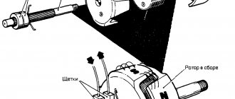
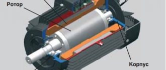
The commutator type motor consists mainly of a rotor, a stator, as well as brushes and a tachogenerator.
- The rotor is part of the rotation, the stator is an external type of magnet.
- Brushes, which are made of graphite, are the main part of the sliding contact, through which voltage is applied to the rotating armature.
- A tachogenerator is a device that monitors the rotation characteristics of a device. If there is a violation in the regularity of the rotation process, then it adjusts the voltage level entering the engine, thereby making it smoother and slower.
- Stator. Such a part may include not one magnet, but, for example, two pairs of poles. At the same time, instead of static magnets, there will be coils of electromagnets. Such a device is capable of performing work both from direct current and alternating current.
Scheme of the speed controller of the commutator motor
Special frequency converters are used in the form of speed controllers for 220 V and 380 V electric motors . Such devices are considered high-tech , and they help to radically transform the current characteristics (signal shape, as well as frequency). They are equipped with powerful semiconductor transistors, as well as a pulse-width modulator. The entire process of operating the device occurs through the control of a special unit on a microcontroller. The change in speed in the rotation of the motor rotor occurs quite slowly.
It is for this reason that frequency converters are used in loaded devices. The slower the acceleration process occurs, the less load will be placed on the gearbox, as well as the conveyor. In all frequency generators you can find several degrees of protection: by load, current, voltage and other indicators.
Some models of frequency converters supply power from a single-phase voltage (it will reach 220 Volts) and create a three-phase voltage from it. This helps to connect an asynchronous motor at home without the use of particularly complex circuits and designs. In this case, the consumer will not lose power while working with such a device.
Why use such a device-regulator?
If we talk about regulator motors , then the required speed is:
- For significant energy savings. So, not every mechanism needs a lot of energy to perform the work of rotating the motor; in some cases, rotation can be reduced by 20-30 percent, which will help significantly reduce energy costs by several times.
- For the protection of all mechanisms, as well as electronic types of circuits. Using the converter frequency, you can exercise certain control over the overall temperature, pressure, as well as other indicators of the device. In the case when the engine operates as a specific pump, then a specific pressure sensor should be inserted into the container into which air or liquid is pumped. When the maximum mark is reached, the motor will simply automatically stop working.
- For the soft start process. There is no particular need to use additional electronic equipment - everything can be done by changing the settings of the frequency converter.
- To reduce device maintenance costs. With the help of such speed controllers in 220 V engines, the possibility of failure of devices, as well as certain types of mechanisms, can be significantly reduced.
Changing the speed of an IM with a squirrel-cage rotor
There are several ways:
- Rotation control by changing the electromagnetic field of the stator: frequency regulation and changing the number of pole pairs.
- Changing the slip of the electric motor by decreasing or increasing the voltage (can be used for IMs with a wound rotor).
Frequency regulation
In this case, the adjustment is made using a frequency conversion device connected to the engine. For this purpose, powerful thyristor converters are used. The process of frequency regulation can be considered using the example of the EMF formula of a transformer:
This expression means that in order to maintain a constant magnetic flux, which means maintaining the overload capacity of the electric motor, the supply voltage level should be adjusted simultaneously with frequency conversion. If the expression calculated by the formula is saved:
then this means that the critical moment has not been changed. And the mechanical characteristics correspond to the figure below; if you do not understand what these characteristics mean, then in this case the adjustment occurs without loss of power and torque.
The advantages of this method are:
- smooth regulation;
- changing the rotor speed up and down;
- rigid mechanical characteristics;
- efficiency.
There is only one drawback - the need for a frequency converter, i.e. increase in the cost of the mechanism. By the way, on the modern market there are models with single-phase and three-phase input, the cost of which with a power of 2-3 kW is in the range of 100-150 dollars, which is not too expensive for full adjustment of the drive of machine tools in a private workshop.
Switching the number of pole pairs
This method is used for multi-speed motors with complex windings that allow you to change the number of pairs of its poles. The most widely used are two-speed, three-speed and four-speed IMs. The adjustment principle is easiest to consider on the basis of a two-speed IM. In such a machine, the winding of each phase consists of two half-windings. The rotation speed changes when connecting them in series or parallel.
In a four-speed electric motor, the winding is made in the form of two parts independent from each other. When the number of pole pairs of the first winding changes, the speed of the electric motor changes from 3000 to 1500 rpm. Using the second winding, rotation is adjusted at 1000 and 500 rpm.
When the number of pole pairs changes, the critical moment also changes. To keep it unchanged, it is necessary to simultaneously regulate the supply voltage while changing the number of pole pairs, for example, by switching the star-delta circuit and their variations.
Advantages of this method:
- rigid mechanical characteristics of the engine;
- high efficiency.
- step adjustment;
- large weight and overall dimensions;
- high cost of the electric motor.
220V electric motor speed controller
You can make it completely independently , but to do this you will need to study all the possible technical features of the device. By design, several types of main parts can be distinguished. Namely:
- The electric motor itself.
- Microcontroller control system for the conversion unit.
- Drive and mechanical parts that are associated with the operation of the system.
Just before starting the device, after applying a certain voltage to the windings, the process of rotating the engine begins with maximum power. It is this feature that will distinguish asynchronous devices from other types. On top of everything else, the load from the mechanisms that set the device in motion is added. Ultimately, at the initial stage of operation of the device, the power, as well as the current consumption, only increases to the maximum level.
At this time, the process of releasing the greatest amount of heat occurs. Overheating occurs in the windings, as well as in the wires. Using partial conversion will help prevent this from happening. If you install a soft start, then to the maximum speed mark (which can also be adjusted by equipment and may not be 1500 rpm, but only 1000), the engine will begin to accelerate not at the first moment of operation, but over the next 10 seconds (at the same time, every second the device will add 100-150 revolutions). At this time, the load on all mechanisms and wires begins to decrease several times.
How to make a regulator with your own hands
You can completely independently create an electric motor speed controller of about 12 V. To do this, you should use a switch of several positions at once , as well as a special wirewound resistor. With the help of the latter, the supply voltage level changes (and at the same time the rotation speed indicator). The same systems can be used to perform asynchronous movements, but they will be less effective.
Many years ago, mechanical regulators were widely used - they were built on the basis of gear drives or their variators. But such devices were considered not very reliable. Electronic means showed themselves several times better, since they were not so large and allowed for finer adjustment of the drive.
In order to create an electric motor rotation controller, it is worth using several devices at once, which can either be bought at any hardware store or removed from old inventory devices. To complete the adjustment process, it is worth including a special variable resistor circuit . With its help, the process of changing the amplitude of the signal entering the resistor occurs.
Implementation of a management system
To significantly improve the performance of even the simplest equipment, it is worth connecting microcontroller control to the engine speed controller circuit. To do this, you should choose a processor that has a suitable number of inputs and outputs, respectively: to connect sensors, buttons, and special electronic keys.
To carry out experiments, it is worth using a special microcontroller AtMega 128 - this is the easiest to use and widely used controller. In free use you can find a large number of schemes using it. In order for the device to perform the correct operation, it is worth recording a certain algorithm of actions - responses to certain movements. For example, when the temperature reaches 60 degrees Celsius (the measurement will be noted on the graph of the device itself), the device should automatically turn off.
Two-channel motor controller
Used to independently control a pair of motors simultaneously. Power is supplied from a voltage ranging from 2 to 12 volts. The load current is rated up to 1.5A per channel.
Device design
The main components of the design are shown in photo.10 and include: two trimming resistors for adjusting the 2nd channel (No. 1) and the 1st channel (No. 2), three two-section screw terminal blocks for output to the 2nd motor (No. 3), for output to the 1st motor (No. 4) and for input (No. 5).
Note:1 Installation of screw terminal blocks is optional. Using a thin stranded mounting wire, you can connect the motor and power source directly.
Principle of operation
The circuit of a two-channel regulator is identical to the electrical circuit of a single-channel regulator. Consists of two parts (Fig. 2). The main difference: the variable resistance resistor is replaced with a trimming resistor. The rotation speed of the shafts is set in advance.
Note.2. To quickly adjust the rotation speed of the motors, the trimming resistors are replaced using a mounting wire with variable resistance resistors with the resistance values indicated in the diagram.
Materials and details
You will need a printed circuit board measuring 30x30 mm, made of a fiberglass sheet foiled on one side with a thickness of 1-1.5 mm. Table 2 provides a list of radio components.
Build process
After downloading the archive file located at the end of the article, you need to unzip it and print it. The regulator drawing for thermal transfer (termo2 file) is printed on glossy paper, and the installation drawing (montag2 file) is printed on a white office sheet (A4 format).
The circuit board drawing is glued to the current-carrying tracks on the opposite side of the printed circuit board. Form holes on the installation drawing in the mounting locations. The installation drawing is attached to the printed circuit board with dry glue, and the holes must match. The KT815 transistor is being pinned. To check, you need to temporarily connect inputs 1 and 2 with a mounting wire.
Any of the inputs is connected to the pole of the power source (a 9-volt battery is shown in the example). The negative of the power supply is attached to the center of the terminal block. It is important to remember: the black wire is “-” and the red wire is “+”.
The motors must be connected to two terminal blocks, and the desired speed must also be set. After successful testing, you need to remove the temporary connection of the inputs and install the device on the robot model. The two-channel motor controller is ready!
THE ARCHIVE contains the necessary diagrams and drawings for the work. The emitters of the transistors are marked with red arrows.
To smoothly increase and decrease the shaft rotation speed, there is a special device - a 220V electric motor speed controller. Stable operation, no voltage interruptions, long service life - the advantages of using an engine speed controller for 220, 12 and 24 volts.
- Why do you need a frequency converter?
- Application area
- Selecting a device
- IF device
- Types of devices
- Triac device
Read also: The principle of operation of a weaving loom
- Converters on electronic keys
- Proportional Signal Process