Very often we encounter the fact that people do not quite understand what primary and backup connection protection is. What’s interesting is that these are not only beginners, but also some already established specialists.
Here are a few myths that I personally encountered:
- Basic protection is protection with absolute selectivity, usually differential
- Basic protection is only available at voltages of 35 kV and above, i.e. at 0.4-10 kV connections there are only backup protections
- There are connections for which there are no backup protections, only basic ones
- There is only one main protection, and there can be several backup ones
Everything that is written above is not true. Let's talk today about primary and backup protections in order to understand some definitions and communicate correctly with fellow relay specialists.
Current protection against short circuit protection
You see that current protection against short-circuit protection at 3Io has disappeared from the mandatory ones. In fact, the PES does not distinguish between types of lines, but for overhead networks the ground fault current may be so small that this protection simply will not work (the relay protection device may not have enough sensitivity of the analog channel to measure 3Io)
Also, on a completely overhead line there are no zero-sequence current transformers (“donut”), and the summation of phase currents gives a large error. At such facilities, all that remains is to use reliable non-selective 3Uo signaling.
However, if the current is still sufficient for the 3Io protection to operate, then it must be used! Also, a short cable insert is often made at the beginning of overhead lines to simplify connection to the switchgear panel. In this case, TTNP is installed on the line, which also improves the performance of protection against OZZ.
It is worth noting that here we are not considering cases where, due to operating conditions, it is necessary to turn off the line when a short-circuit fault occurs (usually at 3Uo). Such requirements exist, for example, in quarries and peat mining. Let's refer this to special electrical installations.
Differential phase protection (PDP)
Transformer protection.
All main types of protection can be divided into two groups:
· Basic
· Reserve
Basic protection is protection with absolute selectivity, usually differential.
Basic protection is only available at voltages of 35 kV and above, i.e. at 0.4-10 kV connections there are only backup protections
There are connections for which there are no backup protections, only basic ones
There is only one main protection, and there can be several backup ones
Basic connection protection
According to the definition of the PUE (clause 3.2.14) - “Each element of the electrical installation must be provided with basic protection designed to operate in the event of damage within the entire protected element with a time shorter than that of other protections installed on this element.”
Thus, at any connection there is always basic protection. This is any protection that protects the entire area and acts faster than other protections. Everything is simple and clear. Now examples.
For a 0.4, 6 or 10 kV line, the main protection is overcurrent protection (overcurrent protection). Protects the entire line and works faster than other defenses. Current cut-off operates faster than overcurrent protection, but it only protects part of the line, i.e. cannot be the main defense. The same is with overload protection - although it reacts to damage throughout the entire area, it works much more slowly than MTZ.
An example with the protection of power transformers. Transformers with a power of up to 6.3 MVA have overcurrent protection as the main protection, but starting from 6.3 MVA and above, differential protection is added. It becomes the main one instead of MTZ, and MTZ becomes a reserve one.
Can there be several main protections on one connection? Yes maybe.
For example, for oil power transformers 6.3 MVA and more, there are usually 2 main protections - differential and gas. Both fit the definition according to clause 3.2.14 because they operate without a time delay and over the entire protected area. Sometimes 3 main protections are installed at the connection, for example, for AT 220 kV and above high power (two differential and gas)
Backup protection
Again, let's first look at the definition (PUE clause 3.2.15) - “To act in the event of failures of protections or switches of adjacent elements, backup protection should be provided, designed to ensure long-range backup action.
If the main protection of an element has absolute selectivity (for example, high-frequency protection, longitudinal and transverse differential protection), then backup protection must be installed on this element, performing the functions of not only long-range, but also short-range backup, i.e., operating in the event of failure of the main protection of this element or removing it from work...”
Thus, backup protection is also always present for any connection.
Just remember one simple thing - at any part of the power system, at any voltage class, there are at least 2 protections - main and backup. Always!
Most often, the backup protection of a connection is the main protection of the upstream connection. This results in a sequential chain of protection in which all stages “crawl” onto each other.
However, if the main connection protection is in the form of differential or phase differential protection, then another protection is needed to provide redundancy for the downstream section. This protection must be stepped because only stepped ones can perform long-range backup.
Results:
Any connection has at least one basic protection
Any connection has at least one backup protection
The main one can be protection performed on any principle (MTZ, DZ DZT, DFZ, etc.)
Only step protection (MTZ or DZ) can be a backup
There may be several main and backup protections at the connection
1. Differential protection (DPP)
used as the main protection of transformers in case of damage to their windings, inputs and busbars. Due to its comparative complexity, differential protection is installed only on single-operating transformers with a power of 6300 kVA and above, on parallel operating transformers with a power of 4000 kVA and above, and on transformers with a power of 1000 kVA and above, if the current cut-off does not provide a protective effect, and the maximum current protection has a time delay more than 1 s.
Differential protection is based on the principle of comparing current values at the beginning and end of the protected section, for example, at the beginning and end of the windings of a power transformer, generator, etc. In particular, the section between current transformers installed on the high and low sides of the power transformer is considered protected zone.
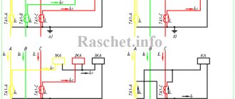
The operation of differential protection is illustrated in Fig. 1. Current transformers TT1 and TT2 are installed on both sides of the transformer, the secondary windings of which are connected in series. A current relay T is connected in parallel to them. If the characteristics of the current transformers are the same, then in normal mode, as well as during an external short circuit, the currents in the secondary windings of the current transformers will be equal, their difference will be zero, and no current will flow through the winding of the current relay T, therefore, the protection will not apply.
Rice. 1. Differential protection of a transformer: a - current distribution in normal mode, b - the same in case of a short circuit in the transformer.
In the event of a short circuit in the transformer and at any point in the protected zone, for example in the winding of the transformer, current will flow through the winding of relay T, and if its value is equal to or greater than the relay operating current, then the relay will operate and, through the appropriate auxiliary devices, will perform a two-way shutdown of the damaged plot. This system will operate during phase-to-phase and interturn faults.
Differential protection is highly sensitive and fast-acting, since it does not require a time delay, it can be performed with instantaneous action, which is its main positive property. However, it does not provide protection against external short circuits and can cause nuisance tripping if there is an open in the secondary circuit connecting wires.
Differential phase protection (PDP)
Operating principle.
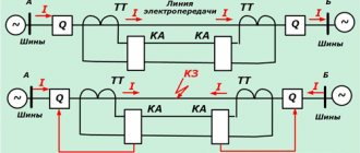
Differential-phase VChZ (DPZ) is based on comparison of current phases at the ends of the protected power line. Considering the currents directed from the buses to the power line to be positive, we find that with an external short circuit in K1 (Fig. 13.3, a) the currents Im and In at the ends of the protected power line have different signs and, therefore, they can be considered phase shifted by 180°. In the case of a short circuit on the protected power line (Fig. 13.3.6), the currents at its ends have the same signs and they can be taken to be in phase if we neglect the shift of the emf vectors Em and En at the ends of the power transmission and the difference in the impedance angles Zm and Zn
The principle of operation of the protection is based on comparing the phases of the connection currents. Currents directed from the busbars into the line are considered positive. These currents are compared by the protection, and if they are in phase, an impulse is sent to open the circuit breakers.
During an external short circuit, the currents at the ends of the line have different phases and are shifted by an angle close to 180°. In this case, the protection is blocked and has no effect on shutdown.
The phases of the currents are compared using RF signals transmitted along the protected line. At each end of the line, the protection has the same type of organs - semi-sets that act on its start-up and disconnection of the circuit breakers.
2. Current cut-off -
The devices of this protection control the amount of current in the protected area.
If the current increases above a certain value, the protection is triggered to turn off this section. The current value at which the protection is triggered is called the setting.
The setting is usually chosen so that the circuit will de-energize before any damage occurs to it. Most often, electromagnetic current relays are used for disconnection, in which contacts close under the influence of electromagnetic force, giving a signal to turn off the circuit breaker of the protected element. Various circuit breakers operate on the same principle.
The amount of electrical current flowing through a circuit during a short circuit depends on where the short circuit occurs. The closer this place is to the current source, the greater the current strength. This property allows this protection to meet the requirement of selectivity. In order for the protection to operate directly in the area in which it is installed, its setting is taken to be greater than the value of the short circuit current outside the protected area. In this case, the protection will not work if a short circuit occurs outside the protected area. Due to this, current cutoff is called protection with absolute selectivity.
In some cases, current cutoff can be made non-selective. In this case, it protects not a separate section of the line, but the entire line. The implementation of such protection is justified by the fact that immediately after its action the automatic reclosure device (AR) begins to operate. If the automatic reclosure is unsuccessful, the differential busbar protection is activated.
3. Gas protection (Buchholtz relay) -
Gas protection for transformers is the most sensitive and versatile protection against internal damage.
It is installed on oil-cooled transformers that have an oil conservator. This type of protection is based on the fact that any damage in the transformer, including increased heating of the oil, leads to chemical decomposition of the transformer oil, as well as organic winding insulation materials, resulting in the release of gas inside the transformer. This gas affects special gas protection devices, which give a warning signal or shut down the transformer. Gas protection
responds to damage such as an interturn short circuit in the transformer windings, to which differential and overcurrent protection does not respond;
since in such cases the magnitude of the circuit current is insufficient to trigger the protection. The nature of the damage in the transformer and the size of the damage affect the intensity of gas formation. If the damage develops slowly, which corresponds to slow gas formation, then the protection gives a warning signal, but does not turn off the transformer. Intense and even violent gas formation, indicating a short circuit, creates a signal in the gas protection system of such a magnitude that, in addition to warning, causes the shutdown of the faulty transformer. Gas protection for transformers also triggers a warning signal when the oil level in the tank drops. Gas protection of transformers
is carried out using
special gas relays
mounted in a metal casing, embedded in the oil line between the tank and the conservator.
Rice. 2. Float-type gas relay: 1 - body, 2.5 - contacts, 3 - rod, 4 - terminal insulation, 6 - cover, 7 - frame, 8 - axis, 9 - upper float, 10 - lower float.
Normally the relay is filled with oil. The relay housing has a sight glass with a scale indicating the amount of gas accumulated in the relay. At the top of the relay there is a valve for releasing gas and clamps for connecting wires to the contacts located inside the relay.
The design and installation of the most common gas relay, type PG-22, is shown in Fig. 1. Gas relays of this type have two floats mounted on hinges inside the casing, which are hollow metal cylinders, and on them are mercury contacts connected by flexible conductors to terminal clamps on the cover relay. The upper float is a signaling element of protection.
In normal condition, when the relay is completely filled with oil, the float floats up and its contact is open. With slow gas formation, gases rising to the conservator gradually fill the relay and displace the oil. As the oil level drops, the float, lowering, rotates on its axis, and the mercury contacts close and a warning signal is sent.
With further slow gas formation, the relay cannot act on shutdown, since it is filled with gas only to the upper edge of the hole, after which the gases will pass into the expander.
The lower float, located opposite the oil line hole, is a shut-off element. If gas formation occurs rapidly, then a strong flow of gases occurs from the transformer into the expander through the gas relay, while the lower float overturns, closes the mercury contacts, which activates the device that turns off the transformer.
Since during short circuits a violent gas formation immediately occurs inside the transformer tank, the transformer turns off quickly, after 0.1-0.3 s. Somewhat later, after the transformer has been switched off, the alarm also goes off.
For transformers with a power of 6.3 thousand kVA and above, the installation of gas protection is mandatory. For transformers with a power from 1000 to 4000 kVA, it is mandatory only in the absence of differential or overcurrent protection with a time delay of 0.5-1 s. For transformers with a power of 400 kVA and above installed inside a workshop, gas protection is required.
4. Maximum current protection (overcurrent) —
Structurally, MTZs consist of two important components: an automatic switch and a time relay. They can be combined in one structure or placed in separate blocks.
Due to the fact that MTZ designs include time relays that delay the operation of cut-off mechanisms, they briefly ignore voltage drops. In addition, current relays are designed in such a way that they return to their original position after eliminating the cause that caused the contacts to open.
There is a dependent connection between the delay unit and the current relay, due to which the shutdown does not occur at the initial stage of current increase, but some time after the occurrence of an emergency situation. This period of time is too short for the current to reach a critical level that could damage the protected circuit. But this is enough to prevent possible false alarms of protective devices.
The operating principle of overcurrent protection systems resembles current cutoff protection. But the difference is that the current cutoff instantly breaks the circuit, and the MTZ does this after some predetermined time. This period, from the moment of emergency increase in current until it is cut off, is called the time delay. Depending on the goals and nature of the protection, each individual time step is set based on calculations.
The shortest time delay is set on the most remote sections of the lines. As the MTZ approaches the current source, the time delays increase. These values are determined by the time required for the protection to operate and are called selectivity levels. Networks built according to this principle form coverage areas of selectivity stages.
This approach provides protection for the damaged section, but does not completely disconnect the line, since the selectivity levels increase as the overcurrent protection system moves away from the accident site. The difference in step sizes allows protective devices located in adjacent areas to remain in a standby state until the current parameters are restored. Since the voltage returns to normal almost immediately after cutting off the zone with a short circuit, the accident does not affect the operation of adjacent areas.
MTZ is used:
· for the purpose of localizing and neutralizing interphase short circuits;
· to protect networks from short-term overloads;
· for de-energizing current transformers in emergency situations;
· as a protector when starting up powerful, volatile equipment.
5. Protection against short circuits to the transformer body -
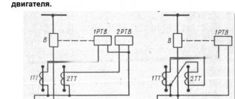
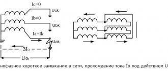
To provide protection against short circuits to the housing, a current transformer CT is inserted into the grounding bus between the housing of the transformer (autotransformer) and the grounding loop of the substation, to the secondary winding of which a current relay T is connected. In case of damage to the windings or inputs of the transformer (autotransformer) in which short circuits occur . Almost the entire short-circuit current passes through the grounding bus to the housing, and only a small part of it is closed directly through the reinforced concrete foundation on which the transformer (autotransformer) is installed.
Figure 3 – Principle of operation of protection against short circuits to the frame.
For external single-phase short circuits in the network connected to the protected transformer (autotransformer), due to the spreading of short-circuit current. part of it is closed through the foundation, housing and grounding bus into which the CT current transformer is embedded. In order for the protection not to operate during external short-circuits, its operation current must be greater than the current passing through the protection during these short-circuits. In our country, this protection is not widespread and is available on transformers (autotransformers) supplied abroad.
6. Transformer overload protection
— on transformers under the supervision of operating personnel, overload protection is carried out by acting on the signal through a single current relay. To avoid unnecessary signals during short circuits and short-term overloads, the relay circuit provides a time relay, the winding of which must be designed for long-term current flow.
Automatic restart
On overhead lines, automatic reclosure (AR) should always be introduced. The algorithm tries to turn on the line after an emergency shutdown, checking for the presence of a short circuit. Often, short circuits on overhead lines clear themselves and then the automatic reclosure is successful.
In Russia, automatic reclosure is usually done for one cycle, i.e. If a short circuit persists on the line, no other automatic switching attempts are made.
Automatic restart is an important element for increasing the reliability of power supply to consumers.
Classification
The entire variety of relay protection devices is classified according to the following main characteristics:
According to the type of connection, they are primary and are connected directly to the electrical network. Secondary devices are connected to it using a transformer, which provides galvanic isolation.
In terms of design, they are produced electromechanically: in them the network is closed and opened using mechanical contacts. In modern electronic devices, semiconductors control the circuit without physically opening the contacts.
According to its intended purpose, it can perform two tasks: logical and measuring functions. Logic devices make decisions based on changing external characteristics of the system. Measuring devices only measure its values.
According to the method of operation, devices are classified into direct and indirect products. Direct acting products are mechanically connected to the shutdown unit, while indirect ones control the power shutoff mechanism.
Design principles
Despite the fact that in the photo all relay protection units look the same, they are produced in different configurations and by different manufacturers. During design, the same performance requirements apply to all components.
In order for the equipment to work properly and not give false positives during design, the following four requirements must be adhered to. These are reliability, sensitivity to operation, speed and selectivity. Reliability is characterized by the following properties: reliability, maintainability, long service life and safety.
Sensitivity characterizes the percentage excess of the measured parameter required for operation. The performance is determined by adding the response time of the logical control unit and the time required to turn off the system.
In some cases a delay is required. For this purpose, special relays are introduced into it. In most cases, immediate response is required. In new manufactured designs, they strive to reduce this time and achieve maximum performance.
Selectivity or selectivity allows you to localize the location of the accident. Thanks to redundancy, the faulty section is switched off, and electricity is supplied bypassing it through serviceable channels. The design of the devices should, if necessary, make it possible to quickly exclude emergency areas and redirect electricity through backup channels.
And if not in an amateurish way
Energy experts think differently. Throughout the entire technological chain of production, transportation and separation of an electrical product, various, including often unpredictable, critical circumstances are possible. And they can create such production excesses that can destroy technical and technological equipment or lead to psychological stress on duty personnel in a split second.
A person is physiologically and psycho-emotionally unable to assess such a short-term situation. Therefore, in a number of energy functions, the human brain has been replaced by installations that are capable of instantly recognizing the impending onset of a breakdown based on deviations in the nominal value of electrical installations. And in automatic control and established algorithms to prevent disasters. This is evidence of why relay protection is needed.
This is how technical vocabulary has developed over the decades, and constant monitoring of all power lines and removal of voltage from them in extraordinary moments is carried out by ultra-modern systems, which are traditionally called relay protection. The term comes from special relays from the protection base of the first Soviet power lines. You can view photos of relay protection.
More types of relay protection and automation
Its technology is used to monitor the performance of all technological systems that use oils for cooling, in particular transformers. Failure in them causes high temperatures with the release of gases from the oil into the atmosphere. At the same time, coolants lose their standard chemical composition and reduce dielectric properties.
Mechanical relay protection instantly responds to such technological failures. It takes into account both changes in the chemistry of gases and the breakdown products of oils.
It can be noted that relay protection works on similar principles even when the following increasing factors appear:
- thermo;
- pressure of a particular environment or prerequisites from mechanics.
And this is not all the main classifications of relay protection - since this article format does not allow us to cover relay protection and automation more widely.
GENERAL PRINCIPLES OF OPERATION OF PROTECTIVE RELAY DEVICES
Relay-based protective devices are varied and can be built according to different circuit diagrams, implemented on different element bases.
What all relay protection devices have in common is the presence of the same functional blocks:
- measuring bodies;
- logic; actuators;
- alarms
The relay measuring element continuously receives information about the state of the controlled object, which can be a separate installation, element or section of the electrical network. There are several approaches to classifying structural blocks of relay protection.
Measuring relay elements are sometimes called trigger elements, but this does not change the essence. Monitoring the condition of an object consists of obtaining and processing the technical parameters of the power supply - current, voltage, frequency, magnitude and direction of power, resistance.
Depending on the value of these parameters, a discrete logical signal (“yes”, “no”) is generated at the output of the relay measuring element, which enters the logic block.
The logical organ, having received a discrete command from the relay measurement unit, in accordance with a given program or logical circuit, generates the necessary command to the executive unit or mechanism.
The alarm unit ensures the operation of signaling devices that indicate the fact of operation of the relay protective kit or its individual element.
To successfully fulfill its mission, URZA must have certain qualities. There are four main requirements that apply to relay protection equipment. Let's look at them separately.
Selectivity.
This property of protective systems is to identify a damaged section of the electrical network and perform shutdowns to the required and sufficient extent in order to separate it. If, as a result of the operation of protective automation, an unnecessary shutdown of the equipment of the power supply system occurs, such operation of the automation is called non-selective.
There are automatic protective systems with absolute and relative selectivity. The first type includes devices that respond only to regime violations strictly within the protected area.
An example of such a protective system is a differential current protective kit, which is triggered only in the event of faults between network points at which the current difference is controlled.
Maximum current systems have relative selectivity, which, as a rule, respond to regime violations in areas adjacent to the area directly protected by them. Typically, in order to avoid non-selective operation, such automation systems have an artificial time delay that exceeds the response time of protective kits in adjacent areas.
Note. Artificial is called a time delay created by special delay elements (time relays).
Performance.
Disabling a damaged section or network element should be carried out as quickly as possible, which ensures the stability of the rest of the system and minimizes the time of interruption of power to consumers.
The main indicator of performance is the response time of the protective device, which is counted from the moment the emergency mode occurs until the protection sends a signal to turn off the circuit breaker.
Sometimes the response time of an automation system is interpreted as the time between the occurrence of a fault and the disconnection of the damaged area, that is, the operating time of the circuit breaker is included in it.
This is not entirely true, since the switch is not part of the relay protection system and its parameters cannot be used to evaluate the effectiveness of relay protection of networks and power supply systems.
That is, it is necessary to take into account the switch off time, but it should be remembered that this is not a characteristic of the relay protection. For reference, you can note that the switch-off time is much longer than the response time of the automation relay itself (without taking into account the artificial delay).
Sensitivity.
This quality characterizes the ability of the automation system to guarantee operation throughout its entire coverage area in case of all types of regime violations for which this automation is designed. The sensitivity of an automation system is an accurate numerical indicator, the value of which is checked in design modes with minimum values of its operation parameters.
Reliability.
A universal characteristic of all technical devices, which consists in the ability of relay protection to function for a long time and without failure. In accordance with its main purpose.
Development of relay protection and automation devices
Previously, in Soviet times (and even now at old substations), electromechanical relays of relay protection and automation were used. For example, the RT-40 and RT-80 series were widely used, which required precise tuning by specialists in the electrical engineering laboratory and had various technical problems due to the low reliability and accuracy of their operation.
Nowadays, domestic and foreign industry produces relay protection and automation devices based on microcontrollers. The reliability of operation, the ability to fine-tune and the versatility of such equipment have been significantly increased.
Well-known manufacturers include: Schneider Electric, ABB, EATON, EKRA, which have become leaders of the Russian market in their field and are successfully used at many domestic industrial enterprises.
Sepam and Micom terminals, which replace a large number of obsolete relays.
Sepam and Micom terminals, which replace a large number of obsolete relays.
Literature
- Fedoseev A. M. “Relay protection of energy systems”: Textbook for universities. M.: “Energy”, 1976. − 560 p. with ill.
- Chernobrovov N.V., Semenov V.A. “Relay protection of energy systems”: Textbook. manual for technical schools. - M.: Energoatomizdat, 1998. −800 pp.: ill.
- Pavlov, G. M. “Automation of energy systems”: Textbook / G. M. Pavlov. - Leningrad: Leningr Publishing House. Univ., 1977.—237 p. : ill.— Bibliography: p.233-234.
- Bulychev, A. V. Relay protection of electric power systems: textbook / A. V. Bulychev, V. K. Vanin, A. A. Navolochny, M. G. Popov. - St. Petersburg: Polytechnic Publishing House. University, 2008. - 211 p.
- RD 153-34.0-04.418-98 “Standard regulations on relay protection and electrical automation services.”
- Shneerson E.M. “Digital relay protection” - M.: Energoatomizdat, 2007. −549 pp.: ill.
Tags: machine, beat, sconce, type, choice, switch, generator, , protective, like, , magnet, magnetic, monitor, power, voltage, nominal, connection, constant, rule, principle, wire, project, start, , work , calculation, relay, repair, row, network, system, resistance, term, circuit, type, current, current, transistor, transformer, installation, photo, shield, effect