The circuits of real electrical installations consist of many elements: conductors, capacitors, microcircuits.
All circuit components are divided into several groups: active, reactive, control elements, power supplies.
The behavior and characteristics of radioelements depend on the type of current flowing (direct, alternating) and on the method of their connection.
What are resistors and capacitors used for?
Resistors are one of the most common elements in electronics.
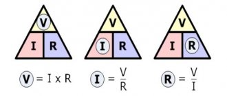
Their main purpose is to resist the flow of current and convert it into heat. The main characteristic of these elements is the value of R. The greater the value of R, the larger part of the electricity can be dissipated into heat. In circuits that are powered by a low voltage from 5 to 12 V, resistors with an R value of 100 Ohm to 100 kOhm are most often used.
Capacitors are devices whose main task is to accumulate electrical charges. It is worth noting that the battery also performs the same function, but unlike a battery, the capacitor immediately releases all the accumulated charge. The amount that a device can accumulate is called “capacity”.
When a circuit is connected to a source of electricity: an electric current flows through the capacitor. The current is at its highest when it first passes through the device, at which time the voltage will become low.
After the device begins to accumulate charge, the current will drop to zero, and the voltage, on the contrary, will begin to increase.
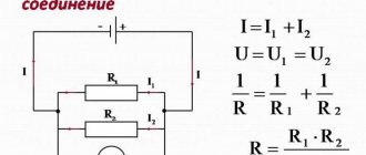
Features of parallel connection of current sources
The following types are distinguished:
- sequential;
- parallel;
- mixed connection.
The electrical circuits of radio-electronic devices contain the most conductors and capacitors. Among all the properties, one parameter is of decisive importance:
- for conductors - resistance;
- for capacitors - capacitance.
With different methods of inclusion in the circuit, the total, resulting value is important; the difference in ratings is not critical.
Current sources are characterized by two parameters:
- electromotive force (EMF) E;
- internal resistance r.
Parallel connection of power sources with different emfs to the load has a serious drawback: even in the absence of an external load, a source with a higher electromotive force is discharged through a source with a lower emf. The process continues until the EMF values become the same, part of the total capacitance is lost.
In electrical engineering, parallel connection of power sources with different characteristics is used to operate on a common load, but not directly.
To be included in the circuit, complex alignment, synchronization, blocking, and protection circuits are used.
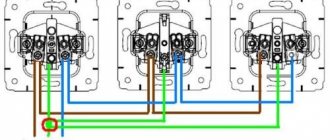
In everyday life, parallel installation of several identical galvanic elements is used: in flashlights, control panels for equipment, in radio-controlled toys.
They connect poles of the same name: plus with plus, minus with minus.
Such inclusion does not require any additional switches or security elements. The EMF between the poles of all sources is equal:
Egen = E1 = E2.
The total current increases, it is equal to the sum of the currents from each source:
Igen = I1+ I2.
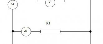
Features of connecting a resistor and capacitor in a circuit
There are two types of connection of resistors and capacitors: parallel and series.
Parallel connection of resistor and capacitor
In order to make a parallel connection of a resistor and a capacitor, it is necessary to combine all the elements of the circuit with two nodes. They should not have connections with other elements.
With such a connection, the voltage between both nodes will drop, and it will become equal for each element. And the value that is the reciprocal of the total R will be equal to the sum of the values that are the reciprocal of the R of all conductors.
When resistors are connected in parallel, the conductivity of all resistors will become equal to the conductivity of the circuit.
If a resistor is connected to a charged capacitor, a short circuit is quite possible.
Serial connection
A serial connection is a connection of elements together so that the initial section of the chain does not have a single node. With such a connection, the magnitude of the current on the conductors will become equal to each other.
RC chain
RC circuit of integrating type
What happens in this circuit if switch S1 is closed?
Capacitor C is initially discharged and the voltage across it is early 0. Therefore, the current at the first moment will be equal to I=U/R. Then the capacitor will begin to charge, the voltage across it will increase, and the current through the resistor will begin to decrease. I=(U-Uc)/R. This process will continue, the capacitor will be charged with a decreasing current to the source voltage U. The voltage on the capacitor will increase exponentially.
Fig. 11. Graph of voltage growth on the capacitor when applying voltage of value U (steps).
Question: And if you power such a circuit from a current generator, how will the voltage across the capacitor increase?
As noted above, the current at the first moment after applying the voltage will be equal to I=U/R, since the capacitor is discharged and the voltage on it is 0. And for some time, while the voltage on the capacitor Uc is small compared to U, the current will remain almost constant. And when charging a capacitor with direct current, the voltage across it increases linearly.
Uc=Q/C, and we remember that current is the amount of charge per second, that is, the rate of charge flow. In other words, the charge is the integral of the current.
Q = ∫ I * dt = ∫ U/R * dt
Uc=1/RC * ∫ U * dt
But all this is close to the truth at the initial moment, while the voltage on the capacitor is low.
What it really comes down to is that the capacitor is charged by a constant current. A direct current is produced by a current generator. (See the question above) If the voltage source produces an infinitely large voltage and the resistance R also has an infinitely large value, then in fact we already have an ideal current generator, and external circuits do not affect the value of this current.
RC chain of differentiating type
Well, everything here is the same as in the integrating chain, only in reverse.
Figure 12. Differentiating chain.
The properties of RC circuits are well covered on the Internet.
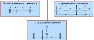
Parallel and series connection of capacitors
Just like resistors, capacitors can be connected in series or parallel.
Source
How to Calculate Impedance in a Circuit
Impedance is the total R of the current, which is denoted by Z. This parameter is a reflection of the time-varying value of the current. Impedance is a vector quantity that consists of two values: active and reactance.
The active part of the impedance, denoted R, is a measure of the degree to which a material will resist the movement of electrons between atomic particles. The more easily atomic particles release or accept electrons, the lower the resistance.
Materials with minimal resistance include steel, aluminum, and gold. The highest R values are glass, mica, polyethylene and are most often called insulators or dielectrics.
It is worth noting! Active R has the same meaning for both serial and parallel connections.
If resistors are used in sinusoidal current circuits, the term "impedance" will be used to indicate resistance R=Z.
Practical impedance calculations are most often performed using the following formula:
Z = Um/Im.
Reactance is denoted by X and is an expression of the degree to which an electronic component in a circuit will store or release electrical energy as the current and voltage fluctuate with each cycle. Reactance is expressed in ohms.
Energy will be stored and released in two types:
- Magnetic field. The reactive part is inductive.
- Electric field.
1.1. CONCEPT OF ALTERNATING CURRENT
Definition: Variables are currents and voltages that change over time, in magnitude and direction. Their value at any time is called the instantaneous value. Instantaneous values are indicated in small letters: i, u, e, p.
Currents whose values are repeated at regular intervals are called periodic. The shortest period of time through which their repetitions are observed is called a period and is denoted by the letter T. The reciprocal of the period is called frequency, i.e. and is measured in hertz (Hz). The quantity is called the angular frequency of alternating current, it shows the change in phase of the current per unit time and is measured in radians divided per second
The maximum value of alternating current or voltage is called amplitude. It is denoted by capital letters with the index “m” (for example, Im). There is also the concept of effective value of alternating current (I). Quantitatively it is equal to:
which for the sinusoidal nature of the current change corresponds to
Alternating current can be written mathematically as:
Here the index expresses the initial phase. If the sinusoid begins at the intersection point of the coordinate axes, then = 0, then
The initial value of the current can be to the left or to the right of the y-axis. Then the initial phase will be leading or lagging.