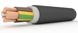
The AAShv cable is used for installing power networks.
It uses an aluminum core as the core. High performance parameters have made the product very popular, the same goes for reliability, low weight and durability. The product is equipped with an additional layer of insulation, therefore it is resistant to low and high temperatures, humidity, and solar radiation.
In 1996, the name of the product changed; now it lacks the last letter “U” (ААШвУ). Previously, it was used to designate wires that could withstand high temperature loads. At the same time, modern products do not differ in design from AAShvU.
This wire may include 1, 3, 4 aluminum cores made from one or more wires. Their shape also comes in different shapes - round or sector. Paper insulation impregnated with a special composition with high viscosity is used as an insulating layer covering the current-carrying part.
Decoding
Product marking indicates the main properties and characteristics. Each index contains certain information that allows you to determine the scope of application of the product. Decoding of cable AAShv:
- aluminum core - A;
- armoring and covering layer of aluminum - A;
- external insulator - pressed protective polyvinyl chloride hose - Sw.
In addition to the main wire, there are also modified products. For example, TSAAShv is equipped with impregnated paper insulation with a high viscosity impregnating composition, and ASShv is equipped with a lead sheath.
Explanation of the name
Everything is simple here, according to traditional Russian typology. The AAShv cable has the following decoding:
- A - aluminum cores;
- A - aluminum armor;
- Ш - surface shell of the “hose” type (sufficiently thick);
- c - vinyl.
This refers to polyvinyl chloride (PVC plastic), from which the hose-type shell is made.
Until 1996, the same wire was called AAShvU. Now the letter “U”, which at one time denoted cable products capable of withstanding a higher heating temperature of the conductors than the standard one, has been canceled and is no longer used. The design itself has not changed.
There is a version of AAShvng - reduced flammability, and AAShvng-ls - reduced flammability, which does not emit harmful substances when melted. The AAShv cable itself does not burn when laid singly; in “non-flammable” versions it does not ignite when laid in a bundle.
Features and Benefits
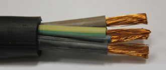
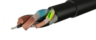
To identify the cores in stranded conductors, the insulating layer is painted in a certain color. For cable brand AAShv, it is possible to use white (yellow), blue, black and red dyes, as well as some of their shades (green, brown, crimson). Coloring can be done in bulk or applied as a separate strip of a certain color.
An alternative option is to apply numerical markings. For this purpose, Arabic numbers 1-4 are provided, which are distributed along the length of the insulator with a certain pitch.
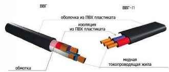
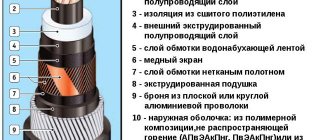
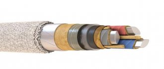
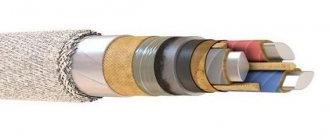
Description and design
This is a power cable that has a composite structure. The protective shell consists of strips made of aluminum. Next, the cord is covered with bitumen paper and standard polyvinyl chloride insulation. The cores themselves are protected by paper containing some non-drip-resistant substance that has the properties of a dielectric.
The cores usually consist of one or more wires, which have a sector shape. Such a wire refers to conductors with a large cross-section (the minimum is 50 sq. mm). The characteristics of AASHv do not provide for a cable with a small diameter. Its dimensions start from 25 mm and reach 800 mm. The number of conductors ranges from one to four.
The flexibility class of a wire with a single-wire core is 1, and with multi-wire cores is 2. Each wire is covered with a layer of several components:
- A separate insulating layer consisting of a paper base and special impregnation.
- A common sheath called the cingulum.
- Paper twists. They are placed between the cores.
- Sheet aluminum. A kind of armor is made from this material.
- A protective layer consisting of bitumen and polyethylene.
- The final layer of insulation. It is made from polyvinyl chloride.
The AAShv wire is used in electrical networks, the minimum voltage of which is 6000 volts. It also has an additional layer of paper, which is capable of conducting electricity. This is necessary for greater cable protection. The component is placed between the screen and the intermediate insulation.
The color marking is the same as for other wires of this class. AASHv has red, white (in some cases yellow), blue, and black veins. Other colors may be used. Cases where the insulating layer is not completely painted, but has only one strip of the required color, are also considered acceptable.
You might be interested in this: Planning and laying hidden wiring in a wooden house
Also, sometimes the manufacturer puts numbers on the wires instead of color. This makes it a little more difficult to decipher the AAShv brand cable, since the color indication is more familiar. Each conductor is assigned a number in the range from 1 to 4.
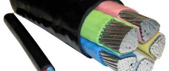
Wire composition
The aluminum power cable AAShv includes:
- The conductive part is made of aluminum, multi-wire for sections 50-800 mm2, single-wire - up to 240 mm2.
- Uniquely colored insulating layer wrapped in impregnated paper.
- Fill the space between the wires with a paper tow.
- Covered with paper insulation.
- Paper screen (conductive).
- Aluminum tube.
- Bitumen and polyethylene terephthalate film.
- External polyvinyl chloride coating with low flammability.
AAShv
Current-carrying conductors must comply with classes 1 or 2. The conductors must be single-wire or multi-wire in accordance with the table.
| Core name | Nominal core cross-section, mm2 | |||
| round | shaped | |||
| copper | aluminum | copper | aluminum | |
| Single wire | 6-50 | 6-240 | 25-50 | 25-240 |
| Stranded core | 25-800 | 70-800 | 25-400 | 70-240 |
Current-carrying conductors of single-core cables of all cross-sections and multi-core cables with a cross-section of up to 16 mm2, as well as multi-core cables with current-carrying conductors of all cross-sections having separate sheaths, must be round in shape.
Conducting conductors of belt-insulated cables with a cross-section of 25 mm2 or more must be sector or segment shaped. It is allowed to manufacture cables with round conductors with a cross-section of up to 50 mm2.
Multi-wire sector and segment cable cores must be sealed during the manufacturing process.
The radius of curvature of single-wire sector cores must be at least 0.5 mm.
The nominal cross-sections of the neutral conductors, in the case of a four-core structure with an unequal cross-section of the main and neutral conductors, are indicated in the table.
| Nominal cross-section of main cores, mm2 | Nominal cross-section of the neutral core, mm2 |
| 6 | 4 |
| 10 | 6 |
| 16 | 10 |
| 25 | 16 |
| 35 | 16 |
| 50 | 25 |
| 70 | 35 |
| 95 | 50 |
| 120 | 70 |
| 150 | 70 |
| 185 | 95 |
Nominal insulation thickness of single-core cables
| Nominal core cross-section, mm2 | Nominal insulation thickness, mm |
| from 10 to 95 | 1,20 |
| from 120 to 150 | 1,40 |
| from 185 to 240 | 1,60 |
| from 300 to 400 | 1.80 |
| from 500 to 630 | 2,10 |
| 800 | 2,40 |
Nominal insulation thickness of multi-core cables
| Rated cable voltage, kV | Nominal cross-section of main cores, mm2 | Nominal thickness, mm | |
| core insulation | waist isolation | ||
| 1 | From 6 to 95 120 and 150 185 and 240 | 0,75 0,85 0,95 | 0,50 0,60 0,60 |
| 6 | From 10 to 240 | 2,00 | 0,95 |
| 10 | From 16 to 240 | 2,75 | 1,25 |
The paper insulation of cables must be impregnated with a viscous or non-drip insulating impregnation compound. In impregnated paper insulation, the tapes should not have folds or tears.
The insulating impregnating non-drip composition should not leak out at the long-term permissible heating temperature of the cable cores.
In paper insulated cables for voltages of 6 kV and more, the coincidence of more than three tapes located one above the other and two tapes directly adjacent to the core or screen superimposed on the core is not allowed.
The coincidence of longitudinal folds or cuts over a length of more than 50 mm in two tapes located one above the other is considered one coincidence.
The insulated cores of multi-core cables must be twisted, filling the spaces between the cores with paper bundles.
Insulated sector cores of multi-core cables for a voltage of 1 kV can be twisted without filling.
The insulated cores of multi-core cables must have a distinctive color or number designation.
The color marking must be durable, not erasable and distinguishable. Marking should be done using colored tapes on the cores or natural colored tapes with stripes that differ from each other in color.
Marking with numbers is done by printing or embossing and must be legible. The color of the numbers when printed must differ from the color of the core insulation. The numbers must have the same color.
With a digital designation, the first core should have the number 1 on the insulation surface or the top strip, the second core should have the number 2, the third core should have 3, and the fourth core should have 4. In this case, number 1 corresponds to white or yellow, number 2 to blue or green, number 3 to red or crimson, number 4 - brown or black.
The insulation of a conductor of a smaller cross-section (zero) can be of any color and may not have a digital designation.
When designating insulated cores with numbers, the distance between them should not be more than 35 mm.
Belt insulation with a nominal thickness in accordance with the table must be applied over the twisted insulated cores of multi-core cables
Under the cable sheath on the surface of the insulation or under the belt insulation on a special tape, no more than every 300 mm, the identification number of the manufacturer and the year of manufacture of the cable must be clearly marked.
In cables with a diameter under the sheath of less than 20 mm, the use of a colored distinctive thread is allowed.
The tape should be made of natural-colored paper. The absence of tape along a cable length of more than 1 m is not allowed. The width of the tape is at least 10 mm. The height of the cipher is at least 6 mm.
Outer diameters of single-core cables with aluminum conductors for voltage 1 kV, mm
| Nominal cross-section of cores, mm2 | AAG | AABl AAB2l | AABlG AABnlG | AAShv AAShng | ASG | ASB | ASBL ASB2l |
| 10 | 8 | 19 | 14,5 | 12,5 | 9 | 17,5 | 18,5 |
| 16 | 9 | 20 | 15,5 | 13,5 | 10 | 18,5 | 19,5 |
| 25 | 10,5 | 21 | 16,5 | 14,5 | 11 | 20 | 21 |
| 35 | 11,5 | 22 | 17,5 | 15,5 | 12 | 21 | 22 |
| 50 | 12,5 | 23 | 19 | 17 | 13 | 22 | 23 |
| 70ozh | 14 | 25,5 | 21 | 18,5 | 14,5 | 24,5 | 25,5 |
| 70 | 15,5 | 27 | 22,5 | 20 | 16,5 | 26 | 27 |
| 95ozh | 15,5 | 27 | 22,5 | 20 | 16,5 | 26 | 27 |
| 95 | 17 | 28,5 | 24 | 21,5 | 18 | 27,5 | 28,5 |
| 120ozh | 17,5 | 29 | 24 | 21,5 | 18 | 27,5 | 28,5 |
| 120 | 19,5 | 31 | 26,5 | 24 | 20 | 29,5 | 30,5 |
| 150ozh | 19 | 30,5 | 26 | 23,5 | 19,5 | 29 | 30 |
| 150 | 21 | 32,5 | 28 | 26 | 22 | 31,5 | 32,5 |
| 185ozh | 21 | 32 | 28 | 25,5 | 21,5 | 31 | 32 |
| 185 | 23,5 | 35 | 30,5 | 28 | 24 | 33,5 | 34,5 |
| 240ozh | 23 | 34,5 | 30 | 28 | 24 | 33,5 | 34,5 |
| 240 | 25,5 | 36 | 33,5 | 31 | 27 | 36,5 | 37,5 |
| 300 | 29 | 40,5 | 36 | 34 | 30 | 39,5 | 40,5 |
| 400 | 32,5 | 44 | 39,5 | 38 | 33,5 | 43- | 44 |
| 500 | 36 | 48 | 43 | 41,5 | 37,5 | 47 | 48 |
| 625 | 40 | 52 | 47 | 46 | 41,5 | 50 | 51 |
| 800 | 45 | 57 | 52 | 51 | 46 | 56 | 57 |
Weights of single-core cables with aluminum conductors for voltage 1 kV, kg/km
| Nominal cross-section of cores, mm2 | AAG | AABl, AAB2l | AABlG, AABnlG | AAShv, AAShng | ASG | ASB | ASBl, ASB2l |
| 10 | 120 | 520 | 370 | 220 | 440 | 690 | 740 |
| 16 | 160 | 580 | 420 | 260 | 520 | 770 | 820 |
| 25 | 200 | 650 | 480 | 310 | 600 | 880 | 930 |
| 35 | 240 | 720 | 550 | 360 | 690 | 980 | 1050 |
| 50 | 300 | 820 | 630 | 430 | 810 | 1100 | 1150 |
| 70ozh | 380 | 1100 | 870 | 520 | 940 | 1400 | 1450 |
| 70 | 410 | 1150 | 950 | 570 | 1100 | 1500 | 1600 |
| 95ozh | 470 | 1200 | 1000 | 630 | 1150 | 1600 | 1700 |
| 95 | 510 | 1300 | 1100 | 690 | 1300 | 1700 | 1800 |
| 120ozh | 570 | 1400 | 1150 | 750 | 1300 | 1800 | 1900 |
| 120 | 640 | 1500 | 1300 | 840 | 1600 | 2050 | 2100 |
| 150ozh | 690 | 1600 | 1300 | 880 | 1600 | 2100 | 2100 |
| 150 | 770 | 1700 | 1450 | 1000 | 1800 | 2300 | 2400 |
| 185ozh | 830 | 1800 | 1500 | 1100 | 1800 | 2300 | 2700 |
| 185 | 950 | 2000 | 1700 | 1200 | 2100 | 2700 | 2800 |
| 240ozh | 1050 | 2100 | 1800 | 1300 | 2200 | 2700 | 2900 |
| 240 | 1200 | 2300 | 2000 | 1500 | 2600 | 3200 | 3300 |
| 300 | 1400 | 2700 | 2300 | 1800 | 3100 | 3600 | 3800 |
| 400 | 1800 | 3100 | 2800 | 2200 | 3700 | 4300 | 4400 |
| 500 | 2200 | 3700 | 3300 | 2600 | 4600 | 5200 | 5300 |
| 625 | 2700 | 4300 | 3900 | 3200 | 5500 | 5900 | 6100 |
| 800 | 3450 | 5200 | 4800 | 4000 | 6600 | 7200 | 7300 |
Outer diameters of three-core cables with aluminum conductors for voltage 1 kV, mm
| Nominal cross-section of cores, mm2 | AAG | AABl, AAB2l | AABlG, AABnlG | AAShv, AAShnG | ASG | ASB | ASBL ASB2l |
| 6 | 12,5 | 23 | 18,5 | 17 | 13 | 22 | 23 |
| 10 | 14 | 25,5 | 21 | 18,5 | 14,5 | 24,5 | 25,5 |
| 16 | 16 | 27,5 | 23,5 | 20,5 | 17 | 26,5 | 27 |
| 25 | 16,5 | 28 | 23,5 | 21 | 17 | 27 | 27,5 |
| 35 | 18,5 | 30 | 25,5 | 23 | 19,5 | 29 | 30 |
| 50 | 21 | 32,5 | 28 | 26 | 22 | 31,5 | 32,5 |
| 70ozh | 23,5 | 35 | 30,5 | 28,5 | 24 | 33,5 | 34.5 |
| 70 | 25,5 | 37 | 32.5 | 30,5 | 26 | 35,5 | 36,5 |
| 95ozh | 26,5 | 38 | 33,5 | 31,5 | 27 | 37 | 38 |
| 95 | 29 | 40 | 36 | 33,5 | 29 | 39 | 40 |
| 120ozh | 29,5 | 41 | 36,5 | 34,5 | 30,5 | 40 | 41 |
| 120 | 33 | 44,5 | 40 | 38 | 34 | 43,5 | 44 |
| 150ozh | 32,5 | 43,5 | 39,5 | 37,5 | 33,5 | 42,5 | 43,5 |
| 150 | 35,5 | 47 | 42,5 | 41 | 35 | 44,5 | 45,5 |
| 185ozh | 35,5 | 47 | 42,5 | 41 | 36,5 | 46 | 47 |
| 185 | 39,5 | 51 . | 46,5 | 45 | 39 | 48 | 49 . |
| 240ozh | 40 | 51,5 | 47 | 45 | 41 | 50 | 46,5 |
| 240 | 45 | 56 | 52 | 50 | 43,5 | 53 | 49 |
Weights of three-core cables with aluminum conductors for voltage 1 kV, kg/km
| Nominal cross-section of cores, mm2 | AAG | AABl, AAB2l | AABlG, AABnlG | AAShv, AAShng | ASG | ASB | ASBl, ASB2l |
| 6 | 240 | 750 | 570 | 370 | 740 | 1050 | 1100 |
| 10 | 310 | 1000 | 810 | 460 | 890 | 1350 | 1500 |
| 16 | 440 | 1200 | 1000 | 600 | 1150 | 1600 | 1700 |
| 25 | 470 | 1250 | 1050 | 630 | 1200 | 1600 | 1750 |
| 35 | 600 | 1450 | 1200 | 780 | 1500 | 1950 | 2050 |
| 50 | 770 | 1700 | 1450 | 1000 | 1800 | 2300 | 2400 |
| 70ozh | 1000 | 2050 | 1800 | 1300 | 2200 | 2700 | 2800 |
| 70 | 1100 | 2200 | 1900 | 1400 | 2400 | 2900 | 3000 |
| 95ozh | 1300 | 2400 | 2100 | 1600 | 2700 | 3300 | 3450 |
| 95 | 1400 | 2600 | 2300 | 1700 | 2900 | 3600 | 3700 |
| 120ozh | 1600 | 2850 | 2600 | 1900 | 3300 | 3800 | 4000 |
| 120 | 1750 | 3100 | 2700 | 2100 | 3600 | 4100 | 4300 |
| 150ozh | 1900 | 3250 | 2900 | 2300 | 3800 | 4400 | 4550 |
| 150 | 2100 | 3600 | 3200 | 2500 | 4100 | 4700 | 4900 |
| 185ozh | 2300 | 3700 | 3300 | 2700 | 4500 | 5100 | 5300 |
| 185 | 2600 | 4200 | 3800 | 3100 | 4900 | 5500 | 5700 |
| 240ozh | 2900 | 4500 | 4100 | 3400 | 5700 | 6100 | 6300 |
| 240 | 3300 | 5100 | 4600 | 3900 | 6100 | 6500 | 6700 |
Outer diameters of three-core cables with aluminum conductors for voltage 6 kV, mm (* - for the cross-section range 25-185 mm2)
| Nominal cross-section of cores, mm2 | AAG | AABl, AAB2l, TsAABL*, TsAAB2l* | AABlG, AABnlG | AAShv, AAShng | ASG | ASB, TsASB | ASBL, ASB2l, TsASBL* |
| 10 | 21 | 32 | 28 | 25,5 | 21,5 | 31 | 32 |
| 16 | 23 | 34,5 | 30 | 28 | 24 | 33,5 | 34,5 |
| 25 | 23 | 34,5 | 30 | 28 | 24 | 33,5 | 34,5 |
| 35 | 25 | 36,5 | 32 | 30 | 25,5 | 35 | 36 |
| 50 | 27,5 | 39 | 34,5 | 32,5 | 28 | 38 | 39 |
| 70ozh | 30 | 41 | 37 | 34,5 | 31 | 40 | 41 |
| 70 | 32 | 43 | 39 | 37 | 33 | 42 | 43 |
| 95ozh | 32,5 | 44 | 39,5 | 38 | 33 | 42,5 | 43,5 |
| 95 | 34,5 | 46 | 41,5 | 40 | 35 | 44,5 | 45.5 |
| 120ozh | 35 | 46,5 | 42 | 40 | 36 | 45,5 | 46 |
| 120 | 39 | 50 | 46,5 | 43,5 | 38 | 48 | 48 |
| 150ozh | 37,5 | 49 | 44,5 | 43 | 39 | 48 | 49 |
| 150 | 41,5 | 53 | 48,5 | 47 | 41 | 50 | 51 |
| 185ozh | 41 | 52 | 48 | 46,5 | 42 | 50,5 | 51,5 |
| 185 | 44,5 | 55 | 51,5 | 50 | 44 | 53 | 54 |
| 240ozh | 45 | 56 | 52 | 50,5 | 45,5 | 54,5 | 55,5 |
| 240 | 49,5 | 61 | 56 | 55 | 49 | 58 | 59 |
Weights of three-core cables with aluminum cores 6 kV, kg/km (* - for the cross-section range 25 - 185 mm2)
| Nominal cross-section of cores, mm2 | AAG | AABl, AAB2l, TsAABL*, TsAAB2l* | AABlG, AABnlG | AAShv, AAShng | ASG | ASB | ASBL, ASB2l, TsASBL* |
| 10 | 600 | 1550 | 1300 | 830 | 1550 | 2050 | 2200 |
| 16 | 750 | 1800 | 1500 | 1000 | 1900 | 2450 | 2550 |
| 25 | 800 | 1800 | 1500 | 1050 | 1950 | 2500 | 2600 |
| 35 | 950 | 2050 | 1700 | 1200 | 2200 | 2750 | 2900 |
| 50 | 1200 | 2350 | 2000 | 1500 | 2600 | 3300 | 3400 |
| 70ozh | 1400 | 2700 | 2300 | 1750 | 3150 | 3700 | 3850 |
| 70 | 1550 | 2850 | 2500 | 1900 | 3400 | 4000 | 4200 |
| 95ozh | 1750 | 3100 | 2700 | 2100 | 3600 | 4200 | 4300 |
| 95 | 1900 | 3300 | 2900 | 2300 | 3900 | 4500 | 4600 |
| 120ozh | 2000 | 3500 | 3100 | 2450 | 4200 | 4800 | 4900 |
| 120 | 2300 | 3800 | 3400 | 2700 | 4500 | 5000 | 5200 |
| 150ozh | 2400 | 3900 | 3500 | 2800 | 4900 | 5500 | 5700 |
| 150 | 2700 | 4300 | 3900 | 3200 | 5300 | 5700 | 5900 |
| 185ozh | 2850 | 4400 | 4100 | 3400 | 5600 | 6100 | 6300 |
| 185 | 3100 | 4900 | 4400 | 3700 | 5900 | 6400 | 6600 |
| 240ozh | 3500 | 5300 | 4800 | 4000 | 6500 | 7100 | 7300 |
| 240 | 3800 | 5700 | 5200 | 4400 | 7100 | 7600 | 7800 |
Outer diameters of three-core cables with aluminum conductors for voltage 10 kV, mm (* - for the cross-section range 25 - 185 mm2)
| Nominal cross-section of cores, mm2 | AAG | AABl, AAB2l, TsAABL*, TsAAB2l* | AABlG, AABnlG | AAShv, AAShig | ASG | ASB, TsASB | ASBL, ASB2l, TsASBL* |
| 16 | 27 | 38,5 | 34 | 32 | 28 | 37,5 | 38,5 |
| 25 | 27 | 38,5 | 34 | 32 | 28 | 37,5 | 38,5 |
| 35 | 29 | 40,5 | 36 | 34 | 30 | 39,5 | 40,5 |
| 50 | 31 | 42,5 | 38,5 | 36,5 | 32,5 | 41,5 | 42,5 |
| 70ozh | 33,5 | 45 | 40,5 | 39 | 35 | 44 | 45 |
| 70 | 35,5 | 47 | 42,5 | 41 | 37 | 46 | 47 |
| 95ozh | 36,5 | 48 | 43,5 | 42 | 37,5 | 47 | 48 |
| 95 | 38,5 | 50 | 45,5 | 43 | 39,5 | 49 | 50 |
| 120ozh | 40 | 50,5 | 46 | 44 | 40 | 49,5 | 50,5 |
| 120 | 42,5 | 54 | 49,5 | 48 | 43 | 51 | 52 |
| 150ozh | 42 | 53,5 | 49 | 48 | 43 | 52 | 53 |
| 150 | 45,5 | 56,5 | 52,5 | 51 | 45,5 | 53,5 | 54,5 |
| 185ozh | 44,5 | 56 | 52 | 50,5 | 44,5 | 54,5 | 55,5 |
| 185 | 48,5 | 60 | 56 | 54 | 48 | 57 | 58 |
| 240ozh | 48,5 | 60 | 55,5 | 54 | 49,5 | 58,5 | 59,5 |
| 240 | 53,5 | 66 | 62 | 59 | 53 | 63 | 64 |
Weights of three-core cables with aluminum conductors for voltage 10 kV, kg/km (* - for the cross-section range 25-185 mm2)
| Nominal cross-section of cores, mm2 | AAG | AABl, AAB2l, TsAABL*, TsAAB2l* | AABlG, AABnlG | AAShv, AAShng | ASG | ASB, TsASB | ASBL, ASB2l, TsASBL* |
| 16 | 1000 | 2200 | 1850 | 1300 | 2400 | 3100 | 3200 |
| 25 | 1050 | 2200 | 1900 | 1350 | 2500 | 3100 | 3250 |
| 35 | 1200 | 2400 | 2100 | 1500 | 2900 | 3400 | 3500 |
| 50 | 1400 | 2700 | 2400 | 1800 | 3300 | 3800 | 3900 |
| 70ozh | 1700 | 3100 | 2700 | 2100 | 3800 | 4400 | 4500 |
| 70 | 1800 | 3300 | 2900 | 2200 | 3950 | 4600 | 4700 |
| 95 oz | 2050 | 3500 | 3100 | 2450 | 4450 | 5100 | 5200 |
| 95 | 2200 | 3800 | 3300 | 2600 | 4600 | 5300 | 5400 |
| 120ozh | 2400 | 3900 | 3500 | 2800 | 4900 | 5500 | 5600 |
| 120 | 2600 | 4300 | 3900 | 3200 | 5100 | 5750 | 5800 |
| 150ozh | 2800 | 4500 | 4000 | 3300 | 5700 | 6100 | 6300 |
| 150 | 3100 | 4900 | 4400 | 3600 | 5900 | 6400 | 6500 |
| 185ozh | 3300 | 5000 | 4600 | 3800 | 6300 | 6900 | 7000 |
| 185 | 3500 | 5400 | 4900 | 4100 | 6800 | 7200 | 7400 |
| 240ozh | 3900 | 5800 | 5300 | 4500 | 7300 | 7800 | 8000 |
| 240 | 4300 | 7000 | 6500 | 5000 | 8000 | 9200 | 9400 |
Outer diameters of single-core cables with copper conductors for voltage 1 kV, mm
| Nominal cross-section of cores, mm2 | SG | SB | SBG | SBl, SB2l |
| 10 | 9 | 17,5 | 13,5 | 18,5 |
| 16 | 10 | 18,5 | 14,5 | 19,5 |
| 25ozh | 11 | 20 | 15,5 | 21 |
| 25 | 11,5 | 20,5 | 16 | 21,5 |
| 35ozh | 12 | 21 | 16,5 | 22 |
| 35 | 13 | 21,5 | 17,5 | 22,5 |
| 50ozh | 13 | 22 | 18 | 23 |
| 50 | 14,5 | 24 | 19,5 | 25 |
| 70 | 16,5 | 26 | 21,5 | 27 |
| 95 | 18 | 27,5 | 23 | 28,5 |
| 120 | 20 | 29,5 | 25 | 30,5 |
| 150 | 22 | 31,5 | 27 | 32,5 |
| 185 | 24 | 33,5 | 29,5 | 34,5 |
| 240 | 27 | 36,5 | 32 | 37,5 |
| 300 | 30 | 39,5 | 35 | 40,5 |
| 400 | 33,5 | 43 | 38,5 | 44 |
| 500 | 37,5 | 47 | 42 | 48 |
| 625 | 41 | 50 | 46 | 51 |
| 800 | 46 | 56 | 51 | 57 |
Weights of single-core cables with copper conductors for voltage 1 kV, kg/km
| Nominal cross-section of cores, mm2 | SG | SB | SBG | SBl, SB2l |
| 10 | 500 | 750 | 600 | 800 |
| 16 | 600 | 870 | 710 | 940 |
| 25ozh | 760 | 1050 | 910 | 1100 |
| 25 | 810 | 1100 | 960 | 1150 |
| 35ozh | 910 | 1200 | 1000 | 1250 |
| 35 | 970 | 1250 | 1100 | 1350 |
| 50ozh | 1100 | 1400 | 1200 | 1500 |
| 50 | 1200 | 1650 | 1450 | 1750 |
| 70 | 1550 | 1950 | 1750 | 2050 |
| 95 | 1900 | 2300 | 2100 | 2400 |
| 120 | 2300 | 2800 | 2500 | 2900 |
| 150 | 2700 | 3200 | 2950 | 3300 |
| 185 | 3300 | 3800 | 3500 | 3900 |
| 240 | 4100 | 4700 | 4400 | 4800 |
| 300 | 5000 | 5500 | 5200 | 5650 |
| 400 | 6200 | 6800 | 6400 | 6900 |
| 500 | 7700 | 8300 | 7900 | 8500 |
| 625 | 9400 | 9700 | 9400 | 10000 |
| 800 | 11500 | 12200 | 11700 | 12400 |
Outer diameters of three-core cables with copper conductors for voltage 1 kV, mm
| Nominal cross-section of cores, mm2 | SG | SB | SBG | SBl, SB2l |
| 6 | 13 | 22 | 17.5 | 23 |
| 10 | 14,5 | 24,5 | 20 | 25,5 |
| 16 | 17 | 26,5 | 22 | 27,5 |
| 25ozh | 17 | 26.5 | 22 | 27.5 |
| 25 | 18 | 27,5 | 23 | 28,5 |
| 35ozh | 19,5 | 29 | 24,5 | 30 |
| 35 | 20 | 29,5 | 25,5 | 31 |
| 50ozh | 22 | 31 | 26,5 | 32 |
| 50 | 23 | 32 | 28 | 33,5 |
| 70 | 25,5 | 35 | 31 | 36 |
| 95 | 29 | 39 | 34,5 | 40 |
| 120 | 33,5 | 43 | 38 | 44 |
| 150 | 37 | 46 | 42 | 47 |
| 185 | 41 | 50 | 45.5 | 51 |
| 240 | 46 | 55 | 51 | 56 |
Weights of three-core cables with copper conductors for voltage 1 kV, kg/km
| Nominal cross-section of cores, mm2 | SG | SB | SBG | SBl, SB2l |
| 6 | 850 | 1150 | 960 | 1200 |
| 10 | 1100 | 1550 | 1300 | 1600 |
| 16 | 1500 | 1900 | 1700 | 2000 |
| 25ozh | 1650 | 2100 | 1850 | 2150 |
| 25 | 1700 | 2200 | 1950 | 2250 |
| 35ozh | 2100 | 2600 | 2350 | 2700 |
| 35 | 2200 | 2700 | 2450 | 2800 |
| 50ozh | 2700 | 3200 | 2900 | 3300 |
| 50 | 2800 | 3350 | 3050 | 3400 |
| 70 | 3600 | 4200 | 3900 | 4300 |
| 95 | 4700 | 5400 | 5050 | 5500 |
| 10 | 5900 | 6450 | 6100 | 6550 |
| 150 | 7200 | 7800 | 7400 | 7900 |
| 185 | 8900 | 9300 | 8800 | 9400 |
| 240 | 11000 | 11500 | 11000 | 11500 |
Outer diameters of three-core cables with copper conductors for voltage 6 kV, mm (* - for the cross-section range 25 - 185 mm2)
| Nominal cross-section of cores, mm2 | SG | SB, TsSB* | SBG | SBL, SB2l, TsSBl* |
| 10 | 21,5 | 31 | 26,5 | 32 |
| 16 | 24 | 33,5 | 29 | 34,5 |
| 25ozh | 24 | 33,5 | 29 | 34,5 |
| 25 | 24,5 | 34 | 30 | 35 |
| 35ozh | 26 | 35,5 | 31 | 36,5 |
| 35 | 27 | 36,5 | 32 | 37,5 |
| 50ozh | 28 | 37,5 | 33,5 | 38,5 |
| 50 | 29 | 39 | 34,5 | 40 |
| 70 | 32.5 | 41.5 | 37 | 42.5 |
| 95 | 36 | 45 | 40,5 | 46 |
| 120 | 39 | 48,5 | 44 | 49,5 |
| 150 | 43 | 51,5 | 47 | 52,5 |
| 185 | 4.6 | 55 | 50,5 | 56 . |
| 240 | 51 | 59,5 | 56 | 61 |
Weights of three-core cables with copper conductors for voltage 6 kV, kg/km (* - for the cross-section range 25 - 185 mm2)
| Nominal cross-section of cores, mm2 | SG | SB, TsSB* | SBG | SBL, SB2l, TsSBl* |
| 10 | 1800 | 2300 | 2050 | 2350 |
| 16 | 2200 | 2750 | 2500 | 2850 |
| 25ozh | 2400 | 2950 | 2650 | 3050 |
| 25 | 2500 | 3050 | 2750 | 3150 |
| 35ozh | 2850 | 3450 | 3100 | 3500 |
| 35 | 3050 | 3700 | 3350 | 3800 |
| 50ozh | 3550 | 4200 | 3900 | 4300 |
| 50 | 3700 | 4400 | 4050 | 4500 |
| 70 | 4650 | 5200 | 4850 | 5300 |
| 95 | 5800 | 6400 | 6000 | 6500 |
| 120 | 6950 | 7600 | 7150 | 7700 |
| 150 | 8350 | 8800 | 8300 | 8900 |
| 185 | 9700 | 10300 | 9600 | 10500 |
| 240 | 12000 | 12500 | 12000 | 12500 |
Outer diameters of three-core cables for voltage 10 kV, mm (* - for the range of sections 25 - 185)
| Nominal cross-section of cores, mm2 | SG | SB, TsSB* | SBG | SBL, SB2l, TsSBl* |
| 16 | 28 | 37,5 | 33 | 38,5 |
| 25ozh | 28 | 37,5 | 33 | 38,5 |
| 25 | 29 | 38,5 | 34 | 39,5 |
| 35ozh | 30 | 39,5 | 35 | 40,5 |
| 35 | 31 | 40 | 36 | 41 |
| 50ozh | 32 | 41,5 | 37 | 42,5 |
| 50 | 33,5 | 43 | 38,5 | 44 |
| 70 | 36,5 | 45,5 | 41 | 46,5 |
| 95 | 40 | 49 | 45 | 50 |
| 120 | 43 | 52 | 48 | 53 |
| 150 | 46,5 | 56 | 51 | 56,5 |
| 185 | 50 | 59 | 54 | 60 |
| 240 | 55 | 65 | 61 | 66 |
Weights of three-core cables with copper conductors for voltage 10 kV, kg/km (* - for the cross-section range 25 - 185 mm2)
| Nominal cross-section of cores, mm2 | SG | SB, TsSB* | SBG | SBL, SB2l, TsSBl* |
| 16 | 2750 | 3400 | 3100 | 3500 |
| 25ozh | 2950 | 3600 | 3300 | 3700 |
| 25 | 3050 | 3700 | 3400 | 3800 |
| 35ozh | 3550 | 4100 | 3750 | 4200 |
| 35 | 3700 | 4200 | 3850 | 4300 |
| 50ozh | 4200 | 4750 | 4400 | 4850 |
| 50 | 4350 | 4900 | 4550 | 5050 |
| 70 | 5300 | 5900 | 5500 | 6000 |
| 95 | 6500 | 7200 | 6700 | 7300 |
| 120 | 7800 | 8200 | 7750 | 8350 |
| 150 | 9000 | 9600 | 9150 | 9800 |
| 185 | 10500 | 11000 | 10500 | 11000 |
| 240 | 13000 | 14000 | 13500 | 14000 |
To avoid damage to the cables, they must be wound on drums with a neck diameter of at least 18 (D+d) for single-core cables in a lead sheath, 15 (D+d) for multi-core cables in a lead sheath and 25 D for cables in an aluminum sheath , where: D is the diameter of the cable along the metal sheath, mm; d - diameter of a round core or diameter of a round core having the same cross-sectional area as a sector or segment core, mm.
Electrical Requirements
The electrical insulation resistance, recalculated per 1 km of length and a temperature of 20 °C, must be at least 100 MOhm for cables with a voltage of 1 kV and 200 MOhm for cables with a voltage of 6 kV and higher. On drums, the cables must withstand an alternating voltage test with a frequency of 50 Hz for 10 minutes in accordance with the table.
Test voltage values
| Rated cable voltage, kV | Test voltage, kV |
| 1 | 4 |
| 6 | 17 |
| 10 | 25 |
The values of the dielectric loss tangent for cables for a voltage of 10 kV are normalized at the level of 0.008 when measured at a voltage of 5 kV.
terms of Use
The service life of the cables is 30 years.
The shelf life of cables in open areas is no more than 2 years, under a canopy - no more than 5 years, in enclosed spaces - no more than 10 years.
The long-term permissible temperature of the cable cores during operation and the maximum permissible temperature of the cable cores during a short circuit should not exceed the values indicated in the table.
Permissible cable temperatures
| Rated voltage, kV | During long-term use | At short circuit current |
| 1 | 80 | 250 |
| 6 | 80 | 200 |
| 10 | 70 | 200 |
Manufacturers
| Cable brand | Manufacturer | Voltage, kV | Range of sections of main cores, mm2 |
| AAG, ASCl | Kamkabel | 1-10 | 35 — 240 |
| AABL | Kamkabel, Irkutskkabel, Moskabelmet, Yuzhkabel | 1-10 1-10 1-10 1-10 | 35 - 240 50 - 240 16-240 (800 for 1) 35-240 |
| AAB2l | Kamkabel, Irkutskkabel, Moskabelmet | 1-10 1-10 | 50-240 16-240 |
| AABlG | Kamkabel, Yuzhkabel | 1-10 1-10 | 35 — 240 35 — 120 |
| AABnlG, AAShng, ASG, ASBl, ASB2l, ASB2lG, ASShv, SB2l, SB2lG | Kamkabel, Moskabelmet | 1-10 | 16-240 (625 for 1) |
| AAShv | Kamkabel, Irkutskkabel, Moskabelmet, Yuzhkabel | 1-10 1-10 1-10 | 50 - 240 16-240 (800 for 1) 35 - 240 |
| ASB, SB | Kamkabel, Sevkabel, Yuzhkabel | 1-10 1-10 1-10 | 35-240 (150 for SB) 6-240 35-240 (120 for SB) |
| ASBG, SBG | Kamkabel, Moskabelmet, Yuzhkabel | 1-10 1-10 1-10 | 35-240 (150 for SBG) 35-240 (800 for 1) 35-120 |
| ASBLShng, SG, SBl, TsAAB2l, TsASBnlShng | Kamkabel, Moskabelmet | 1-10 1-10 | 35-240 (150 for SG, SBL) 16-240 (400 for 1) |
| TsASB, TsASBL | Kamkabel, Moskabelmet, Saranskkabel | 6-10 6-10 6-10 | 35 — 240 70 — 240 35 — 240 |
| TsSB | Kamkabel, Saranskkabel | 6-10 6-10 | 35-150 35 — 240 |
| TsSBl | Kamkabel, Saranskkabel | 6-10 | 35 — 240 |
Specifications
Technical characteristics of cable AAShv:
| duration of work | 30 years; |
| guaranteed duration of work | 4.5 years; |
| length of segments | 200-450 m depending on the cross-section (inversely proportional); |
| bend radius | 25D; |
| installation temperature | more than 0 degrees Celsius; |
| humidity | 98%; |
| core temperature during a short circuit lasting 4 minutes | 200 degrees Celsius; |
| emergency core temperature | 80 degrees Celsius; |
| working temperature | -50/+50 degrees Celsius; |
| sheath resistance | 200 MOhm/km; |
| DC/AC voltage | 25000/10000 V; |
| current frequency | 50 Hz. |
When laid in groups, they do not support or spread combustion.
Scope of application of the AAShv cable:
The cables are intended for the transmission and distribution of electrical energy in stationary installations in electrical networks for voltages up to 35 kV with a frequency of 50 Hz. The cables are intended for use in macroclimatic areas with moderate and cold climates.
The cables are intended for use in the ground (trenches) with low and medium corrosive activity with the presence or absence of stray currents, with high corrosive activity with the absence of stray currents, if the cables are not subjected to tensile forces during operation. The cables are intended for use outdoors, in dry rooms, in damp, partially flooded rooms with low, medium and high corrosive activity, as well as channels, cable mezzanines, shafts, collectors, industrial premises, on technological racks, on special cable racks and on bridges, in the absence of danger of mechanical damage during operation. The cables are used for installation in fire hazardous areas and explosive zones of classes V-Ib, V-Id, V-II, V-IIa. The cables are flame retardant when laid individually (IEC 60332-1 standards). Cables with non-draining insulating impregnation composition (CAASHv) are intended for laying on vertical and inclined sections of routes without limiting the difference in levels. The cables can be used in places subject to vibration. The service life of the AAShv cable is at least 30 years.
| Core cross-section, sq. mm | Construction length, m |
| up to 70 | 300-450 |
| 95 and 120 | 250-400 |
| 150 or more | 200-350 |
Price
You can purchase this wire from us at a competitive price in record time. This is due to the fact that we work directly with manufacturers, which reduces the cost of the product and the risk of purchasing low-quality and non-original goods.
You can purchase wire from the assortment available in the warehouse or place an order from the manufacturer. We deliver cable and wire products to any city in Russia, cooperate with individuals and legal entities, sell goods at retail and wholesale.
To formulate a profitable commercial offer, you must leave a request on the website or send it by email. Our employees will quickly formulate the terms of purchase, after which we can immediately begin shipping. There are promotions and special offers for regular customers, which allows you to save on a quality product. The price is determined based on the type of wire, its design and materials, as well as a number of other factors. For detailed information, contact our consultants or leave a request.
Meanings of letters in markings
Basic information about the conductor is contained in its markings. The decoding of the letters ААШв means the following:
- The letter “A” at the beginning of the mark indicates the material of the current-carrying conductor. In this case, aluminum.
- The second “A” is aluminum protective armor. Protects against external mechanical damage.
- “Ш” – the outer sheath is made of a hose. Outer layer of the cable.
- “c” – PVC coating. Outer shell material.
Explanation of power cable markings More detailed markings contain information about the cross-section and number of current-carrying wires. For example, AAShv 3x70 means that the cable consists of 3 conductors. The cross section of each is 70 square meters. mm.
Installation and operating conditions
Installation is carried out in closed and open ways:
- in the ground;
- by air;
- overpasses, bridges, pipelines;
- in underground structures;
- at high humidity of premises, risk of flooding;
- in an aggressive environment.
When laying a route, environmental parameters should be monitored. Installation without preheating is allowed only at positive temperatures. It is also necessary to minimize tensile stresses, which can reduce the quality of the product and its technical characteristics.
When laying in the ground, it is necessary to eliminate the risk of stray currents due to high corrosive activity; if this indicator is low or average, their occurrence is allowed.
When installing a main line from AAShv wire in water, it is worth remembering that the design load increases by 10%.
TSAAShv 3x150
Characteristics of cable TSAAShv 3x150
The TSAAShv 3x150 cable is intended for power transmission in fixed installations in networks at an alternating current voltage of 6 kV-10 kV V with a frequency of 50 Hz. A distinctive feature of the cable design is a special non-drip impregnation. For cables with non-draining paper insulation, the viscosity of the composition is higher and at operating temperatures of the cable and permissible level differences during installation the composition does not move. Cables that are intended to be laid vertically have either weakly impregnated insulation or insulation with a non-draining composition. A cable with depleted impregnation is treated with a vacuum after impregnation, and ceresin, a substance obtained from oil, is added to the non-draining impregnation, due to which the impregnation does not drain, and this in turn prevents depressurization of the cable.
Decoding of the power cable TSAAShv 3x150
- C - Paper insulation impregnated with a non-drip compound containing ceresin
- A - Aluminum conductor
- A - Aluminum shell
- Shv - Protective cover in the form of a hose made of polyvinyl chloride plastic.
Cable design elements TSAAShv 3x150
- Aluminum conductor:
- single-wire (class 1) with a cross-section of 25-240 sq. mm., -multi-wire (class 1 and 2) with a cross-section of 70-240 sq. mm.;
Phase paper insulation impregnated with a viscous or non-drip insulating impregnation compound
core markings: - digital: 1, 2, 3, 4, - color: white or yellow, blue or green, red or crimson;
Filling from paper bundles; Belt paper insulation impregnated with a viscous or non-drip insulating impregnation compound; Screen made of electrically conductive paper for cables for voltages of 6 kV and more; Aluminum shell; Sublayer of bitumen and PET film; Outer cover made of PVC plastic.
Scope of application of cable TSAAShv 3x150
The peculiarity of all cables with non-drip impregnation is that they can be laid without limiting the difference in height, unlike cables with viscous oil-rosin impregnation in accordance with GOST 18410-73E. For cables with viscous impregnation, if the permissible height is exceeded, it is necessary to use special locking couplings. The reason is that if there is a difference in height when laying a cable with viscous impregnation, there is a possibility of the insulation impregnation draining, and this can lead to depressurization of the cable or a decrease in the electrical strength of the cable.
Most often, the TSAAShv 3x150 cable is used in temperate and cold climates (from -50 to +50). The cable can be subjected to tensile loads. The cable TSAAShv 3x150 is resistant to vibration. Thanks to this, TSAAShv 3x150 can be installed near vibration sources, for example, in residential and public buildings near engineering equipment, in industrial buildings near forging and press equipment, compressors, diesel hammers, etc. The cable can also be laid in earthen trenches, regardless of corrosive activity and stray currents.
The cable is laid single. There are all the necessary passports and certificates.
The total service life of the cable is at least 30 years. Manufacturers provide a warranty period of 4.5 years.
Cost of cable TSAAShv 3x150
The best manufacturers
The cable and wire products market offers a wide range of products, when choosing which you should be guided by the advice of experts and the reputation of the manufacturer. We recommend choosing products made by:
- Lyudinovo cable;
- Sevkabel;
- Tatkabelem;
- Kamkabel;
- Sarankable.
This guarantees high quality, compliance with industry standards, excellent technical characteristics, and durability of the product. These AAShv manufacturers are the most in demand today. At the same time, you should beware of fakes that have a short service life and not such high performance parameters.
Parameters, characteristics, purpose
Insulation:
The purpose of insulation is to provide the necessary electrical strength. The layer depends on the nominal parameters and design:
Monolithic conductors,
| Rated cable voltage, kV | Nominal core cross-section, mm2 | Nominal insulation thickness, mm |
| From 10 to 95 | 1.2 | |
| » 120 »150 | 1.4 | |
| 1 | » 185 »240 | 1.6 |
| » 300 » 400 | 1.8 | |
| » 500 » 630 | 2.1 | |
| 800 | 2.4 | |
| 20 | From 25 to 95 | 7 |
| » 120 » 400 | 6 | |
| 35 | From 120 to 400 | 9 |
Protected stranded conductors have the ratio,
| Rated cable voltage, kV | Nominal core cross-section, mm2 | Nominal thickness, mm | |
| core insulation | waist isolation | ||
| From 6 to 95 | 0.75 | 0.05 | |
| 1 | 120 and 150 | 0.85 | 0.6 |
| 185 and 240 | 0.95 | 0.6 | |
| 6 | From 10 to 240 | 2 | 0.95 |
| 10 | From 16 to 240 | 2.75 | 1.25 |
The insulation resistance of one kilometer of length is equal, mOhm:
- 100, voltage 1000 volts;
- 200, over 6000.
Conductors
The cross-section and material of the core determines the amount of electrical resistance:
| Nominal cross-section, mm | Minimum number of core wires | Electrical resistance of 1 km of core at a temperature of 20℃, Ohm, no more | |
| Single-wire (1 cl) | Stranded (2 cells) | ||
| 10 | 1 | 7 | 3.08 |
| 16 | 1 | 7 | 1.91 |
| 25 | 1 | 7 | 1.2 |
| 35 | 1 | 7 | 0.868 |
| 50 | 1 | 19 | 0.641 |
| 70 | 1 | 19 | 0.443 |
| 95 | 1 | 19 | 0.032 |
| 120 | 1 | 37 | 0.253 |
| 150 | 1 | 37 | 0.206 |
| 185 | 1 | 37 | 0.164 |
| 240 | 1 | 37 | 0.125 |
| 300 | 1 | 61 | 0.1 |
| 400 | 1 or 35 | 61 | 0.0778 |
| 500 | 1 or 35 | 61 | 0.0605 |
| 625, 630 | 1 or 59 | 91 | 0.0469 |
| 800 | 1 or 59 | 91 | 0.0367 |
| For solid aluminum alloy conductors, the electrical resistance value shown in the table is multiplied by 1.162, unless otherwise specified in an agreement between the manufacturer and the customer. |
Examination
High-voltage products are tested at voltages:
| AC voltage test 50 Hz, 10 minutes | |||||
| Rated cable voltage, kV | 1 | 6 | 10 | 20 | 35 |
| Test voltage, kV | 4 | 17 | 25 | 20 | 35 |
| The DC test voltage value is 2.4 times higher than AC |
For products of 6 kV or more, a four-hour test is carried out:
| For cables 6 kV and more: AC voltage test 50 Hz, 4 hours | ||||
| Rated cable voltage, kV | 6 | 10 | 20 | 35 |
| Test voltage, kV | 24 | 40 | 80 | 115 |
Temperature conditions
The use of cable paper as insulation made it possible to expand the operating temperature range, °C:
- Normal interval, -50 ÷ +50;
- Maximum permissible humidity 98%, 35
- Laying the wire without heating is prohibited, below, 0;
- Long-term permissible heating, lasting no more than 4 seconds of short circuit, with overload up to 8 hours continuously:
| Rated cable voltage, kV | Long-term permissible heating temperature of cable cores, °C | Maximum permissible heating temperature of cable cores, °C | ||
| single-core or in a separate sheath for each insulated core | with waist insulation | at short circuit current | when overloaded | |
| 1 | 80 | 80 | 250 | 105 |
| 6 | — | 80 | 200 | 105 |
| 10 | — | 70 | 200 | 90 |
| 20 and 35 | 65 | — | 130 | — |
The service life depends on the technical condition of the cable, more than 30 years.
Analogues of AVBBShv
AVBbShvng(A) - Difference: the protective hose is made of a polyvinyl chloride composition of reduced fire hazard; group laying is allowed.
AVBbShvng(A)-LS - Difference: the protective hose is made of a polyvinyl chloride composition of reduced fire hazard and with reduced gas and smoke emission.
In some cases, AVBBShV can be replaced with the following models:
- ApvBbShv, in which polyethylene is used instead of a PVC shell;
- AVBbShvz is filled with a non-vulcanized rubber mixture;
- AVVBG does not have a protective shell.
An analogue should be selected in accordance with the operating conditions of the cable. It may not be appropriate to use an analogue in all situations.