How often do Russian users (homeowners and industrial enterprises) receive low-quality electricity and overpay for energy resources due to ineffective energy supply systems? Almost always. And this is despite the decrees of the Government of the Russian Federation and orders of the Ministry of Energy, which came into force more than 10 years ago. And the problem of low efficiency and improved quality is solved - it is enough to install a reactive power compensation device with characteristics suitable for a particular situation.
Preface
One of the reasons for the occurrence of additional losses in electrical networks is the forced transfer of reactive power generated by the main inductive consumers of electrical energy (electric motors, transformers, reactors, etc.). Reactive power consumption is characterized by power factor (cos φ). The higher the power factor value, the less additional losses in the networks. Thus, the problem of increasing the power factor arises as one of the important measures to reduce losses in networks, associated with a reduction in reactive power consumption by electrical receivers.
Reference
Conducted at the Moscow Energy Institute under the guidance of Doctor of Technical Sciences, Prof. Abramovich B. N. studies of the influence of power quality on the operation of electrical equipment have shown that if standard indicators of power quality (QE) are violated, the service life is reduced:
- power transformers 10/0.4 - 1.2-1.8 times;
- asynchronous electric motors - 1.5-2.5 times;
- drives, soft starters and frequency converters - 2.0-4.1 times.
For example, the cost of damage from poor quality electrical energy to the US economy is estimated at more than $150 billion per year (2005 data).
How is the damage from poor quality electricity in the Russian economy assessed?
There are no official statistics on the severity and distribution of voltage drops, but some regional measurements are being carried out which may provide food for thought. For example, a study conducted by a major power producer measured voltage drops at 12 sites ranging from 5 to 30 MVA. Over 10 months, 858 changes were recorded, 42 of which led to failures and financial losses. Although in all these 12 sites the consumers were producers with simple technology, financial losses amounted to 600 thousand euros, and the maximum amount of losses per site was 165 thousand euros.
The concept of active and reactive power
In electrical circuits containing a combined load, the total power consumed from the network consists of active power, which performs useful work, and reactive power, spent on creating magnetic fields and creating an additional load on the power supply lines. The relationship between total and active power, expressed through the cosine of the angle between their vectors (cosφ), is called power factor.
In electrical networks containing only active loads (incandescent lamps, electric heaters, etc.), the current and voltage change in phase, and only useful active power is consumed from the network.
But in real life this happens quite rarely. The main load in industrial electrical networks is asynchronous electric motors and distribution transformers. During operation, this inductive load is a source of reactive electricity (reactive power), which oscillates between the load and the source (generator).
Reactive power is characterized by a delay (in inductive elements the phase current lags behind the voltage) between the phase sinusoids of the voltage and network current.
The phase lag of the current from the voltage in inductive elements causes time intervals when the voltage and current have opposite signs: the voltage is positive and the current is negative and vice versa. At these moments, power is not consumed by the load, but is supplied back through the network towards the generator. In this case, the electrical energy stored in each inductive element is distributed throughout the network without being dissipated in the active elements, but performs oscillatory movements (from the load to the generator and back).
An indicator of reactive power consumption is the power factor (PF), numerically equal to the cosine of the angle (φ) between current and voltage. The consumer's power consumption is defined as the ratio of the consumed active power to the total power actually taken from the network, i.e. cos(φ)=P/S.
The appearance of a reactive component in a network can be displayed on vector diagrams as follows:
This coefficient is usually used to characterize the level of reactive power of engines, generators and the enterprise network as a whole.
The closer the cos(φ) value is to unity, the smaller the share of reactive power taken from the network
For most industrial consumers, the presence of reactive energy in networks means the following: through the networks between the source of electricity and the consumer, in addition to the active energy that performs useful work, reactive energy also flows, which does not perform useful work and is aimed only at creating magnetic fields in the inductive load. Flowing through the cables and windings of transformers, the reactive current reduces, within their capacity, the proportion of the active current flowing through them, causing significant additional heating losses in the conductors - i.e. active losses. It follows from this that, according to modern rules for paying for electricity, the consumer is forced to pay at least twice for the same unproductive costs. Once - directly for the reactive energy consumed from the network (according to the reactive energy meter) and the second time - for the same, but indirectly, paying for active losses from the flow of reactive energy, taken into account by the active energy meter.
Thus, the presence of reactive power is a parasitic factor that is unfavorable for the network as a whole. As a result:
- electricity costs increase;
- you have to pay fines for reducing the quality of electricity due to a reduced power factor
- additional losses occur in conductors due to increased current;
- the load on transformers and switching equipment increases, thus reducing their service life
- the load on wires and cables increases - you have to use a larger cross-section;
- The network voltage deviates from the nominal value (voltage drop due to an increase in the reactive component of the supply network current).
- the level of higher harmonics in the network increases
Benefits of use
The installation of UKRM helps to increase the energy efficiency of energy carriers and reduce the likelihood of breakdowns of industrial equipment to zero. Moreover, this type of compensation is environmentally friendly and does not cause any harm to the environment or human health. The advantages of using devices for consumers and specialists include:
- increase in useful power (efficiency of electrical networks and equipment up to 97%);
- reduction in the amount of actually consumed energy by 20-30%;
- increasing voltage level stability;
- increasing the period of trouble-free operation of equipment;
- reduction in utility costs (electricity);
- reducing the throughput in electrical networks (minimizing the risk of overheating and short circuit).
Using UKRM in production also allows you to avoid costs such as fines from state control authorities.
specializes in the production of modern technology that helps reduce energy costs. Our task is to satisfy consumer requests and provide devices that are 100% suitable for the assigned tasks. The UKRM range includes various functionality, designs, and types of operation, so we are confident that every consumer will be able to choose a device with optimal characteristics.
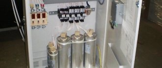
Capacitor installations
To reduce reactive power in industrial networks, capacitor units have become widespread.
Capacitor installation (KU, or UKRM - reactive power compensation installation) - according to the current GOST 27389-87, this is an electrical installation consisting of capacitors and related auxiliary electrical equipment (reactive power regulator, contactors, fuses, etc.).
Select the required capacitor unit (calculator)
Selecting compensation mode
Depending on the location where the heat exchanger is installed, the following types of compensation are distinguished: centralized on the high side (a), centralized on the low side (b), group (c) and individual (d) (see figure below).
- With centralized compensation on the high voltage side, when a capacitor unit is connected to the busbars of a 6-10 kV transformer substation, good use of capacitors is obtained, fewer of them are required and the cost of 1 kvar of installed power is minimal compared to other methods. When compensation according to this scheme, only the higher-lying links of the power system are unloaded from reactive power, and in-plant distribution networks and even substation transformers remain unloaded from reactive power, and therefore, energy losses in them do not decrease and the power of transformers at the substation cannot be reduced.
- With centralized compensation on the low voltage side, when the capacitor unit is connected to the 0.4 kV buses of the transformer substation, not only the upstream 6-10 kV networks, but also the transformers at the substation are unloaded from reactive power, but the 0.4 kV in-plant distribution networks remain unloaded .
- With group compensation, when capacitor units are installed in workshops and connected directly to workshop distribution points (DP) or 0.4 kV buses, transformers at substations and 0.4 kV power networks are unloaded from reactive power. Only distribution networks to individual power receivers remain unloaded . In order to evenly distribute the compensating devices, it is advisable to connect the capacitor installation to the RP buses in such a way that the reactive load of this RP is more than half the power of the connected capacitor installation.
- With individual compensation, when the capacitor unit is connected directly to the terminals of the electrical receiver consuming reactive power, which is the main requirement for creating reactive power as close as possible to the place of its consumption, this method will be the most effective in terms of unloading power and distribution networks, transformers and networks from reactive power higher voltage. With individual compensation, self-regulation of reactive power generation occurs, since capacitor units are turned on and off simultaneously with the drive electric motors of machines and mechanisms.
The most common methods of compensating the reactive power of power supply to industrial enterprises is group compensation; options for the combined placement of capacitor units are also possible. The determination of the most advantageous solutions for choosing a method of reactive power compensation is made on the basis of technical and economic calculations, thorough studies of production conditions, design factors, etc. When choosing the location of a capacitor installation in a distribution network, it is necessary to take into account its effect on the voltage regime and the amount of energy losses in networks. As a rule, reactive power compensation should be carried out in the same network (at the same voltage) where it is consumed, with minimal energy losses and, consequently, lower transformer powers.
Selecting the compensation type
Depending on the requirements for the characteristics of the equipment and the complexity of control, the KRM can be of the following types:
- unregulated - by connecting a capacitor bank of fixed capacity;
- automatic - by switching on a different number of control stages to supply the required reactive energy;
- dynamic – to compensate for rapidly changing loads.
Unregulated compensation
The circuit uses one or more capacitors to provide a constant level of compensation. Management can be:
- manual: using a circuit breaker or load switch;
- semi-automatic: using buttons and a contactor;
- direct connection to the load and switching on/off with it.
Capacitors are connected:
- to the input terminals of inductive loads (mainly electric motors);
- to busbars supplying groups of small electric motors or inductive loads for which individual compensation can be quite expensive;
- in cases where the load factor must be constant.
Automatic compensation
This type of compensation provides for automatic maintenance of a given cos φ by regulating the amount of generated reactive energy in accordance with load changes. KRM equipment is installed and connected to those places in the electrical installation where changes in active and reactive power are relatively large, for example:
- to the busbars of the main distribution board;
- to the terminals of the cable supplying a powerful load.
Unregulated compensation is used where it is necessary to compensate for reactive power not exceeding 15% of the rated power of the transformer power source. If more than 15% compensation is required, it is recommended to install a capacitor bank with automatic regulation. Control is usually carried out by an electronic device (reactive power controller) that monitors the actual power factor and issues commands to connect or disconnect capacitors to achieve a given factor. Thus, the reactive energy is regulated in steps. In addition, the reactive power controller provides information about the characteristics of the electrical network (voltage amplitude, distortion level, power factor, actual active and reactive power) and the condition of the equipment. In case of malfunction, alarm signals are generated. The connection is usually provided by contactors. To quickly and frequently switch capacitors when compensating for highly varying loads, semiconductor switches should be used.
Dynamic compensation
This type of PFC is used to prevent voltage fluctuations in networks with changing loads. The principle of dynamic compensation is that, together with an unregulated capacitor bank, an electronic reactive power compensator is used, which provides advance or lag of reactive currents relative to voltage. The result is fast-acting variable compensation, well suited for loads such as elevators, crushers, spot welders, etc.
Taking into account operating conditions and harmonic content in the network
Capacitor installations should be selected taking into account the operating conditions throughout the entire service life of the components, primarily capacitors and contactors.
Accounting for operating conditions
Operating conditions have a significant impact on the service life of capacitors. The following parameters should be taken into account:
- ambient temperature (°C);
- expected increased currents associated with voltage waveform distortion, including maximum continuous overvoltage;
- maximum number of switching operations per year;
- required service life.
Taking into account the impact of harmonics
Depending on the amplitude of the harmonics in the electrical network, various configurations of PFC devices are used:
- Standard capacitors: in the absence of significant non-linear loads.
- Capacitors of increased rating: in the presence of minor non-linear loads. The current rating of capacitors must be increased so that they can withstand the circulation of harmonic currents.
- Higher value capacitors with anti-resonance chokes are used in the presence of numerous non-linear loads. Chokes are necessary to suppress the circulation of harmonic currents and prevent resonance.
- High harmonic filters: in networks with a predominance of non-linear loads, where harmonic suppression is required. Filters are typically designed for a specific electrical installation based on on-site measurements and a computer model of the electrical network.
Negative cosine
From the school geometry course we know that cos (φ) = cos (-φ), that is, the cosine of any angle will be a positive value. But how can you distinguish an inductive load from a capacitive one? It's simple - electricians in all countries have agreed that when there is a capacitive load, a minus sign is placed in front of the cosine sign!
In the practice of using the HIOKI voltage analyzer, I had cases when the cosine value was negative. Subsequently, it turned out that the compensating installation was turned on incorrectly and overcompensation occurred. That is, cos φ < 0, which is as it should be, but capacitor units are used incorrectly, and situations are possible when the voltage in the network may rise because of this.
Accessories for UKRM
Capacitors
Capacitors are part of any reactive power compensation installation (unregulated or automatic) and are used to adjust the power factor of inductive consumers (transformers, electric motors, rectifiers) in electrical networks for voltages up to 660 V.
Design
The most popular three-phase reactive power compensation capacitors consist of a cylindrical aluminum housing, inside of which three single-phase capacitors are mounted, connected in a delta pattern (see Fig. option a). The connection is made via three terminals. There are also models (for example from Legrand) with six terminals (see Fig. option b) they allow you to connect the contactor to a delta gap. Which in turn allows you to use a contactor of a lower rating.
The capacitor body contains a dielectric with three polypropylene layers metallized with aluminum and zinc. This coating provides a low level of losses and high resistance to high pulse currents, and also promotes self-healing of the capacitor in the event of a breakdown. Depending on the operating voltage, polypropylene film has different thicknesses. In this case, the metallization layers act as current conductors (i.e., plates), and polypropylene is a dielectric. After completing the necessary technological operations and passing quality control, the capacitive elements (rolls) are placed in aluminum cylindrical cases and filled with polyurethane resin, which is non-toxic and has high environmental properties.
Production technology and self-healing of capacitors
The starting material for the production of capacitors is polypropylene film. At the beginning of the technological process, metallization of the polypropylene film occurs to form a conductive layer 10-50 nm thick on it from a mixture of zinc and aluminum. The use of a material with the specified characteristics makes it possible to achieve a self-healing effect in the event of a dielectric breakdown between the capacitor plates. In this case, electrical energy evaporates the metal around the damaged area and thereby prevents a short circuit. The loss of capacitance during this process is quite insignificant (about 100pF). The self-healing ability guarantees high operational reliability and long service life of the capacitor. To minimize the dielectric loss tangent, two layers of zinc coating, which is called zinc bonded edge, are applied to the ends of the capacitor sections. This ensures tighter contact between the capacitor leads and the capacitor section.
Overpressure protection
To ensure protection of the internal elements of the capacitor, most manufacturers use a built-in disconnector that is triggered when excess pressure occurs. The purpose of the device is to interrupt the short circuit current when the capacitor reaches the end of its service life and is incapable of subsequent recovery. This device breaks the electrical circuit of the capacitor using the internal pressure that occurs during the destruction of the film from overheating caused by short circuit current.
Use of capacitors with rated voltage above 400V.
Since voltage directly affects the reactive power of the capacitor, companies offer lines of capacitors with different rated voltages Un - 400, 440, 460, 480, 525V. In 380V networks, with stable network voltage parameters, it is recommended to use capacitors with Un - 400V, in this case, the use of capacitors with Un - 440V and higher is impractical, because the rated power is significantly reduced (approximate correction factors 230V - 1.74 / 440V - 0.91 / 480V - 0.83 / 525V - 0.76) According to the EN-60831.1-2 standard, capacitors at industrial frequency must withstand a voltage of l.10*Un (1.10*400 = 440V) for at least 8 hours a day. In cases where increased network voltage persists for more than 8 hours, it is necessary to use capacitors with Un - 440V. The use of this type of capacitor guarantees reliable operation in a network with increased voltage and an increase in the service life of the capacitor.
Attention! Residual stress
After disconnecting the capacitor from the network, residual voltage is still present at its terminals, which poses a danger to operating personnel. To eliminate this, all three-phase capacitors are equipped with discharge resistors, which reduce the voltage level to less than 75V in 3 minutes.
Attention! overheat protection
To ensure reliable natural cooling, the distance between the capacitor banks should be: 2.5 - 25 kVAr, at least 25 mm. 30 - 50 kVAr not less than 50mm.
Circuit breakers
Fuses are part of any reactive power compensation installation (unregulated or automatic) and are used to protect against short circuits. The most commonly used fuses are NH format.
The IEC 60269 and VDE 0636 standards govern the selection of fuses for use in electrical circuits with inductive loads. This standard does not consider cases where the power factor cos φ is less than <0.1, or the load is capacitive in nature. Currently, the certification testing standards for fuse breaking parameters and characteristics only apply to inductive loads and are not valid for capacitive loads. Despite this, it is possible to use fuses with a gG switching characteristic to protect reactive power compensation capacitors, provided that the following rules are observed.
Attention!
Fuses should not be used to protect capacitors from overload. Overload protection must be provided by an internal overpressure switch installed in the condenser. Fuses should only be used to protect against external or internal short circuits of capacitors or capacitor installations. Ignoring this rule may lead to damage to the reactive power compensation installation, resulting in destruction of the fuse housing. When choosing fuses to protect capacitors, the following rules must be observed: - The fuses must continuously withstand the maximum operating current of the capacitors, which is 1.5 x In. Based on this requirement, it is recommended to choose a fuse with a rating of 1.6 - 1.8 of the rated current of the capacitor (with cos φ not less than 0.7). — The fuses must be able to withstand the inrush currents of the capacitor. When switching capacitors, a large inrush current occurs, exceeding the rated value by up to 100 times. These current surges gradually reduce the life of the fuse, which can ultimately lead to overheating and false operation. Properly selected fuses (1.6 -1.8 of the capacitor's rated current) using electromechanical contactors for switching three-phase capacitors or semiconductor contactors that are activated when the voltage crosses zero avoid the negative effects of inrush currents. — Long-term operation of capacitors and fuses is not permissible in the presence of higher harmonics or resonance in the network. At the rated frequency of the supply network, the capacitors have such a resistance that eliminates the possibility of an overload. Devices generating higher harmonics place additional stress on fuses and capacitors. In industrial networks, higher harmonics can reach values comparable to the first harmonic. In this case, fuses selected with lower than required rated currents and voltages may overheat and fail, followed by destruction of the fuse-link housing. In the presence of higher harmonics, the only solution is to use filter chokes to protect the reactive power compensation installation from unacceptable overloads. — The selection of fuses must be made taking into account the influence of the compensation (flowing) current that occurs between nearby capacitors of the installation. When a capacitor is switched or a fault occurs, a compensation current begins to flow between adjacent capacitors. In this situation, the rated current of the fuses to protect the capacitors must be selected several orders of magnitude higher. The total rated current of a group of fuses must be at least 2.5 times higher than the rated current of a single fuse. — The fuses must be able to withstand the high recovery voltage. Resonance and restarting (charging) with discharged capacitors can generate a reverse voltage that exceeds the network voltage and, as a consequence, the rated voltage of the fuses. When the current drops to zero, the supply voltage Ue and the capacitor voltage Un reach their maximum value. When switched off at the moment the current passes through zero, the capacitor voltage remains unchanged at the moment when the supply voltage reaches its maximum value with the opposite sign. The amplitude of the recovery voltage Uf applied to the fuse increases by 2 times (maximum 2.5 times in three-phase networks) for 5 ms. When a recharge occurs (turning on), the capacitor instantly changes its polarity to the opposite, while the recovery voltage continues to increase. Repeated rapid charging of the capacitor can damage fuses and other equipment in the electrical installation. The risk of fuse failure due to excess recovery voltage can be minimized by selecting a fuse with a high voltage rating relative to the operating voltage of the system, as well as by using larger fuses. It is also necessary to take into account the requirement for the discharge time of the capacitor when it is turned on again (usually this time is about 3 minutes and is set by the controller managing the installation).
Selection of fuses and cross-section of connected conductors for a 3-phase network with a voltage of 400V / 50Hz in Table 1
Table 1
| Rated capacitor power, Qn (kvar) | Rated capacitor current, In (A) | Rated fuse current gL/gG, Un=500V, (A) | Cross-section of connected conductors, copper (mm²) |
| 2,5 | 3,6 | 10 | 2,5 |
| 5 | 7,4 | 16 | 2,5 |
| 7,5 | 10,8 | 20 | 2,5 |
| 10 | 14,4 | 25 | 4 |
| 12,5 | 18,1 | 32 | 6 |
| 15 | 21,6 | 35 | 6 |
| 20 | 29 | 50 | 10 |
| 25 | 36 | 63 | 10 |
| 30 | 43 | 80 | 16 |
| 40 | 58 | 100 | 25 |
| 50 | 72 | 125 | 35 |
| 60 | 87 | 160 | 50 |
| 75 | 108 | 160 | 50 |
| 80 | 115 | 200 | 70 |
| 100 | 144 | 250 | 95 |
| 120 | — | 250 | — |
| 125 | — | 315 | — |
| 150 | — | 355 | — |
| 175 | — | 400 | — |
| 200 | — | 500 | — |
| 225-250 | — | 500 | — |
| 275/300 | — | 630 | — |
| 350-400 | — | 800 | — |
Note! The values of rated currents of protective fuses and cross-sections of connected conductors indicated in the table (approximate) are valid for normal operating conditions (at an ambient temperature of no more than 30°C, in the absence of harmonic distortion in the network and when the requirements for the assembly of this type of installation are met, etc.) .P.). In all other cases, you should carefully calculate the parameters of the protective elements, taking into account correction factors and operating conditions. The value of the rated current of the capacitor at different voltages can be recalculated using the corresponding coefficients: (230V - 1.74 / 440V - 0.91 / 480V - 0.83 / 525V - 0.76). However, it should be taken into account that the above values of the coefficients are conditional, because they are influenced by: the temperature inside the cabinet, the quality of the cable, the maximum temperature of the cable insulation, the use of single or multi-core cable, and its length.
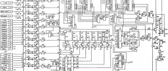
Reactive power regulators
Reactive power regulators are included only in automatic reactive power compensation units.
Power factor correction regulators in low-voltage systems determine the actual value of cos φ and automatically connect or disconnect steps to achieve the required power factor value. The operating principle of the controller is based on the FCP system, which allows instantaneous measurements of voltage and current values, ensuring optimal control of the reactive power compensation system. If there is no need for automatic configuration, all parameters can be set manually. Most controllers have the ability to connect and program an external fan to cool the capacitor banks, and they also have an over-temperature alarm. Typically, reactive power measurements are made in 4 quadrants, which provides the maximum degree of compensation for consumed energy.
To compensate for power at different loads, regulators monitor the active and reactive components of power by measuring instantaneous voltage and current values in the electrical network. Based on these measurements, the phase shift between current and voltage is calculated and this value is compared with a preset cos φ value. Depending on the actual deviation of the power factor, the controller issues a command to control the stages of the capacitor banks with a minimum response time of 4 seconds (programmable).
Regulatory methods
The reactive power regulator digitizes the measured line voltage between two phases and the current in the third phase (most often). Then, from these values, the device calculates: power factor, effective voltage and current values, harmonic distortion for voltage and current. The required power for compensation is calculated using the set required value of the reactive power factor in the device. Based on these values, the controller switches the corresponding capacitor stages on or off.
- APFR (average power factor regulation) or instantaneous cos φ regulation: The controller monitors the average power factor based on active and apparent power over a certain period of time. This method ensures that the controller correctly tracks load changes based on load level and cos φ. Thanks to the APFR system, the reactive power compensation controller reduces the number of step switchings without making adjustments to the controller settings.
- SHTD : This method uses a slower response time depending on the magnitude of the difference between the set power factor and the measured instantaneous value. For every second, the difference in time relative to the reaction decreases by the square of the difference to 0 (the moment of reaction).
- Instantaneous power factor change: This method responds to each instantaneous change in power factor by connecting or disconnecting the required capacitor stage based on the most appropriate power step step. This method is mainly used for dynamic power factor correction system based on thyristor switching modules.
Additional functions of regulators
- Temperature rise control - the controller provides two levels of temperature rise alarm capability. The first level provides ventilation for the cabinet. The second level switches off all stages of the capacitor unit and issues an alarm signal on the display. Many types of regulators do not have independent alarm outputs, but the last stage can be used as an emergency output. In this case, it is used only as an emergency signal output and is not used for switching contactor stages.
- Many regulators are equipped with interfaces for transmitting information to external control systems. For example, an RS485 interface with a Modbus RTU communication protocol.
- Decompensation - the controller can provide the function of using decompensating (inductive reactor) stages; in this case, the stage can be both inductive and capacitive in nature. Decompensating reactor stages are used in two cases: at facilities where there is only a capacitive load - in this case, all stages of the regulator operate inductively; and at facilities where there are inductive and capacitive loads - in this case, one stage can operate inductively, and the remaining stages will be capacitive.
- Some reactive power compensation regulators provide the ability to operate according to two cos φ tariff plans. The second tariff cos φ is configured in the service menu of the controller and is activated by supplying power to a separate input (for example Tariff).
Contactors for switching three-phase capacitors
Contactors for switching three-phase capacitors are also included only in automatic reactive power compensation units.
During the operation of capacitor units for reactive power compensation when regulating stages, capacitor banks are subject to frequent switching. Unlike other types of electrical equipment, when switching capacitor banks, in addition to the rated operating current, a large starting current arises, significantly (up to 250 times) exceeding the rated value. Therefore, specially designed high-speed contactors must be used to switch capacitors. Unlike conventional ones, they are equipped with an additional contact group installed parallel to the main one. Removable current-limiting elements consisting of several turns of conductor with high resistivity are connected in series to the auxiliary contacts on both sides. When switching, both groups of contacts are activated simultaneously, but due to the shorter distance limited by the stop, the auxiliary contacts close a few milliseconds before the main ones, pass the starting current through the current-limiting elements, thereby limiting the current of the capacitor bank and open 5 milliseconds after reliable closure main power contacts.
Otherwise, current surges can lead to damage (sticking) of the power contact group and negatively affect the service life of the contactor. Limiting the inrush current also helps avoid voltage sags during transients. This feature of the contact group guarantees stable and efficient operation throughout the entire service life of the contactor.
Contactors for capacitors are often equipped with normally open and/or closed auxiliary contacts.
Filter chokes
Three-phase chokes are designed for operation as part of capacitor installations, they are connected in series with capacitors and are used as a protective, filtering device against the influence of higher harmonics on the consumer network and on the capacitor. As the frequency of the applied voltage to the capacitor increases, its resistance decreases, so chokes are used, which together with the capacitor form a circuit that is tuned to the harmonic frequency and suppresses it. The resonance frequency of such a circuit must be lower than the frequency of the lowest harmonics present in the electrical network. In the presence of harmonics with frequencies higher than the frequency of the circuit formed by the capacitor and inductor, resonance does not occur. Standard values of the detuning coefficient are 5.67%, 7% and 14% at resonant frequencies of 210.189 and 134 Hz in networks with a nominal frequency of 50 Hz. With such standard values of quantities in a three-phase network and a symmetrical load, it becomes possible to eliminate the 5th (250 Hz) and higher order harmonics. This avoids resonance between the inductive reactance and the three-phase capacitors included for power factor correction and prevents overloading of the capacitor banks. Often chokes are equipped with a bimetallic thermal relay, which is built into the central winding and has outputs to separate terminals. The relay sensor is triggered at temperatures above 90°C.
Select the required capacitor unit (calculator)
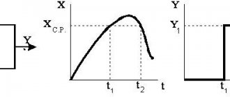
Plant measurements
With the inductive nature of the load, which is observed in practice in most cases, the current lags behind the voltage (negative phase shift), which can be seen on the screen of the HIOKI 3197 device (tabular data) when taking measurements:
Vector diagram
In this case, it can be seen that the current lags behind the voltage by approximately 26°.
From the above measurement it is clear that at a current lag angle (phase shift) of 26° cos φ = 0.898. This calculation is confirmed by the measured value.
The measurement was carried out for about two hours, during which time the equipment (load) was turned on and off cyclically. During the entire measurement period, the coefficient of nonlinear voltage distortion THD did not exceed 1.3% for each phase.
The measurement results are shown below:
Measured harmonics of voltage, current and power
Multimeter mode - different parameters on the screen
To check, let’s carry out the calculation using the above formula for the most intense harmonics (5, 7, 11):
Voltage harmonic calculation
As can be seen, the remaining harmonics have negligible weight.
THD timeline:
THD (Total Distortion) graph
Cosϕ time graph:
Cosine Phi
Useful literature
| Automatic power control of capacitor units. Electrician's Library - 451. V.P. Ilyashov. Energy Moscow, 1977 (PDF, 15.6 MB) |
| Compensation of reactive power in electrical installations of industrial enterprises. Electrician's Library - 429. V.M.Glushkov, V.P.Gribin. Energy Moscow, 1975 (PDF, 11.7 MB) |
| Reactive power compensation. Electrician's Library - 445. B.A. Konstantinov, G.Z. Zaitsev. Energy Leningrad, 1976 (PDF, 12.7 MB) |
| Reactive power. Electrician's Library - 476. G.P.Minin. Energy Moscow, 1978 (PDF, 10.9 MB) |
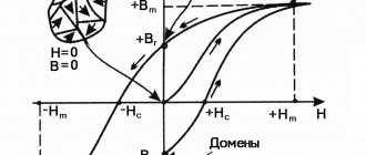
Supply voltage harmonics
In addition to the generation of reactive power, at industrial enterprises there is such a negative factor as the generation of harmonics in the supply network voltage.
Harmonics are that part of the supply voltage spectrum that differs from the industrial network frequency of 50 Hz. As a rule, harmonics are formed at frequencies that are multiples of the fundamental. Thus, the 1st (fundamental) harmonic has a frequency of 50 Hz, the 2nd - 100, the 3rd - 150, and so on.
To measure voltage harmonics there is a formula:
Voltage harmonics - calculation formula
Where:
- Кu – coefficient of nonlinear distortion, or THD (Total Harmonic Distortion),
- U(1), U(2), and so on – the voltage of the corresponding harmonic, up to the 40th.
However, this formula is not convenient in practice, since it does not give an idea of the level of each harmonic separately. Therefore, for practical purposes, use the formula:
Ratio of each voltage harmonic
Where:
- Кu(n) – coefficient of the nth harmonic component of the voltage spectrum,
- U(n) – voltage of the nth harmonic,
- U(1) – 1st harmonic voltage
Thus, during the measurement we will obtain a detailed distribution of harmonics in the spectrum of the supply voltage, which will allow us to conduct a detailed analysis of the information received and draw the right conclusions.
There are also current harmonics, but everything is much worse there...
Based on the increase in current harmonics, a device was built to deceive the meter. By the way, there the author of the device quite convincingly proved the benefits of his invention)
MKPg - a new generation of dry capacitors produced by Electronicon
The use of impregnating materials and fillers is necessary to protect capacitor electrodes from the effects of acids, humidity and other environmental interference. Without such insulation, corrosion of metal plates and an increase in the number of individual partial discharges will occur. The consequence of this would be an increase in electrical losses and a reduction in service life. For many years, Electronicon specialists have been exploring different ways to achieve reliable capacitor preservation. Although until recently excellent success has been achieved with PUR resin and mineral oil used for these purposes, experts decided to develop a new type of capacitor for particularly high environmental requirements. This type is based on MPP technology, which has proven itself over many years in conditions of increased overload.
Rice. 6. Design of a metal film capacitor manufactured using MKP/MKPg technology
Table 7. Comparative characteristics of capacitors manufactured using MKP and MKPg technologies
After numerous laboratory studies and extensive practical testing, Electronicon introduces a new generation of MKP capacitors with environmentally friendly filler (gas) - MKPg. The new technology guarantees the same high technical qualities, the same proven operating safety and reliability as previously produced MKP synthetic resin capacitors.
These capacitors:
- Particularly environmentally friendly - the gas that fills the new condenser is completely neutral. Thus, when destroying old capacitors, there is no problem of leakage of harmful liquids or gases.
- They have convenient installation with a high degree of protection, which guarantees optimal sealing of the capacitor, allows convenient connection of cables with a cross-section of up to 25 mm2, and allows direct installation of discharge chokes.
- They are tight and reliable. With normal maintenance of capacitors, gas leakage is almost impossible. Even if leakage occurs, it will not be due to interference or contamination. Gas leakage over a long period of time may lead to a decrease in the capacity value. Studies have shown that this process extends over many years, during which the capacitor remains functional. Even in the event of damage to the capacitor, for example, resulting from prolonged overloads or non-recoverable breakdowns in the dielectric, the internal pressure in the capacitor will build up with sufficient force and speed that it can be switched off by the circuit breaking mechanism. In other words, even in the event of gas loss, the protection mechanism works flawlessly.
- Significant weight reduction. Thanks to the use of inert gas as a filler, the weight of MKPg capacitors is on average 15–20% less than their analogues. This will bring not only advantages during transportation and maintenance, but also greater reliability in any installation of capacitors.
Single-phase and three-phase capacitors with a diameter of 35–75 mm, three-phase capacitors with a diameter of 50–75 mm.
The body is extruded aluminum with a mounting bolt.
The cover is plastic, the body with a rubber seal.
For capacitors of the 275.ХХХ and 276.ХХХ series, depending on the requirements, including the characteristics of the terminals, various designs are used. In Fig. Figure 7 shows the most commonly used solutions.
Rice. 7. Examples of the design of Electronicon capacitors
Electricity consumers
All electricity consumers are divided into linear and nonlinear. Linear consumers take from the network, with an applied sinusoidal voltage, a sinusoidal current, which can be shifted in phase relative to the voltage. Linear consumers are:
- three-phase electric motors;
- capacitors;
- incandescent lamps;
- resistive heating elements.
Nonlinear consumers take a non-sinusoidal current from the network with an applied sinusoidal voltage. Nonlinear consumers are:
- valve electric drives;
- frequency converters;
- units and backup power units;
- dimmers, television sets;
- elements with a saturated magnetic circuit;
- luminaires with gas-discharge lamps;
- arc furnaces, welding machines;
- power semiconductor devices.
Bit modules
For L/M capacitors, Electronicon offers six different discharge modules (3x68, 82, 100, 120, 180, 300 kOhm) for discharging single capacitors or groups of capacitors connected in series. The resistors are mounted in a touch-proof housing (IP20). The discharge modules are designed to discharge up to 50 V in less than 60 s.
For capacitors with design A, similar discharge groups (IP00) are also available. The discharge modules are designed to discharge up to 50 V in less than 70 s.
Capacitors with design K are equipped with internal discharge modules designed to discharge up to 50 V in less than 60 s.
Specific plug-in values can be calculated using the following formulas:
- Three phase capacitor:
- Single phase capacitor:
t
- discharge time,
CT
- capacity of one phase,
Ctotal
- total capacity,
UB
- operating voltage,
UE
- maximum permissible voltage for time
t
,
R
- resistance value.
In conclusion, let's look at several examples of choosing the required capacitor power in practice.
MKP (metal film) capacitors manufactured by Electronicon
Design
The capacitors are made of Al-Zn metallized polypropylene film with a self-healing dielectric, filled with PUR resin. These capacitors are mounted in an aluminum housing with protection against overpressure (Fig. 1, 2).
Both end sides of the section are metallized by sputtering and guarantee a high current load and low-inductive contact between the leads and the section. Extruded aluminum is used for the capacitor housing with mounting bolt.
The section is dried under vacuum. After installation, the capacitor housing is filled with polyurethane resin. This achieves an increase in the service life of the capacitor, stability of its capacity and improved protection from environmental influences.
Advantages of MKR capacitors
Due to direct metallization of the film with the same film dimensions and the same field strength, they have smaller overall dimensions than previously used MPP capacitors. With dimensions identical to MPP, a higher load voltage can be achieved (with the appropriate dielectric thickness). Due to the absence of a paper liner, there is no need for an expensive vacuum drying process.
Single-phase and three-phase capacitors have a diameter of 75–136 mm, extruded aluminum housing with mounting screw and aluminum cover.
Additional advantages of MKR capacitors:
- particularly beneficial for the environment;
- independence of the operating properties of capacitors from the installation method;
- tightness and reliability;
- significant weight reduction compared to MRR.
Analysis of the survey results obtained
The company had to select a compensating unit to increase the power factor. But before purchasing it, it was decided to pay attention to the harmonics.
There were real cases when, due to high levels of voltage harmonics, capacitor units exploded and caught fire
GOST 13109-97 specifies the permissible level of voltage harmonic distortion equal to 8%. According to the measurements taken, this level has not been exceeded. However, with a 5x increase in power, you can expect an increase in harmonic harmonic content (THD) by the same amount. Therefore, it is possible to increase the harmonic distortion from 2.3% to 11,5 %.
However, according to manufacturers' recommendations, for the safe operation of capacitor banks of standard installations, the THD level should not exceed 2%. In this case, the level of current harmonics is not taken into account and is not regulated by GOST.
Therefore, it is necessary to use high-pass filters (filter compensating devices) in conjunction with capacitor units.