Main characteristics
In order to determine the feasibility of manufacturing a generator using neodymium magnets, you need to consider the main characteristics of this material, which are:
- Magnetic induction B is a strength characteristic of a magnetic field, measured in Tesla.
- Residual magnetic induction Br is the magnetization possessed by a magnetic material when the external magnetic field strength is zero, measured in Tesla.
- Coercive magnetic force Hc - determines the resistance of a magnet to demagnetization, measured in Amperes/meter.
- Magnetic energy (BH)max - characterizes how strong the magnet is.
- Temperature coefficient of residual magnetic induction Tc of Br – determines the dependence of magnetic induction on the ambient temperature, measured as a percentage per degree Celsius.
- Maximum operating temperature Tmax - determines the temperature limit at which the magnet temporarily loses its magnetic properties, measured in degrees Celsius.
- Curie temperature Tcur - determines the temperature limit at which a neodymium magnet is completely demagnetized, measured in degrees Celsius.
The composition of neodymium magnets, in addition to neodymium, includes iron and boron and depending on their percentage, the resulting product, the finished magnet, differs in classes, differing in their characteristics given above. A total of 42 classes of neodymium magnets are produced.
The advantages of neodymium magnets that determine their demand are:
- Neodymium magnets have the highest magnetic parameters Br, Hsv, Hcm, VN.
- Such magnets have a lower cost compared to similar metals containing cobalt.
- They have the ability to operate without loss of magnetic characteristics in the temperature range from – 60 to + 240 degrees Celsius, with a Curie point of +310 degrees.
- From this material it is possible to make magnets of any shape and size (cylinders, disks, rings, balls, rods, cubes, etc.).
How to use the energy of weak winds?
The use of weak wind flows can be done in two directions:
- the use of devices that are structurally different from common models
- use of more efficient generators capable of producing sufficient energy at low rotation speeds
Practice shows that the search should be conducted in both directions. The development of new versions of the impeller, capable of reliably rotating at low flows, is ongoing, and there are already many prototypes demonstrating quite successful results.
Equally active is the development of productive generators that make it possible to use weak winds as a source of energy. Thus, axial generators on neodymium magnets give a great effect and allow you to obtain a good amount of energy. Some craftsmen note the emerging need to limit the possibility of accelerating the rotation of the rotor, i.e. motion stability is needed.
Rotor options capable of efficient operation in low winds have been known for decades. Currently, designs by Tretyakov and Onipko can be used; sailing wind turbines are highly efficient. An integrated approach to modernizing the design of wind generators, when both the impeller and the generator are simultaneously modified, gives a positive result.
The situation is somewhat complicated by the unofficial nature of the work being carried out. If an inventor wants to share his findings with the public, then everyone will know about them, but if he does not consider it necessary to make his findings public, then the information will become closed from discussion and comprehension.
Wind generator on neodymium magnets with a power of 5.0 kW
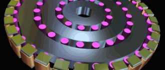
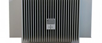
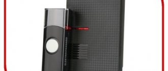
Currently, domestic and foreign companies are increasingly using neodymium magnets in the manufacture of low-speed electric current generators. Thus, Salmabash LLC, Gatchina, Leningrad Region, produces similar permanent magnet generators with a power of 3.0-5.0 kW. The appearance of this device is shown below:
The generator housing and covers are made of steel, later coated with paint and varnish materials. The housing is equipped with special fastenings that allow you to secure the electrical device to the supporting mast. The inner surface is treated with a protective coating that prevents metal corrosion.
The generator stator is made of electrical steel plates.
The stator winding is made of enamel wire, allowing the device to operate for a long time at maximum load.
The generator rotor has 18 poles and is mounted in bearing supports. Neodymium magnets are placed on the rotor rim.
The generator does not require forced cooling, which is carried out naturally.
Technical characteristics of the 5.0 kW generator:
- Rated power – 5.0 kW;
- Rated frequency – 140.0 rpm;
- Operating rotation range – 50.0 – 200.0 rpm;
- Maximum frequency – 300.0 rpm;
- Efficiency – not less than 94.0%;
- Cooling – air;
- Weight – 240.0 kg.
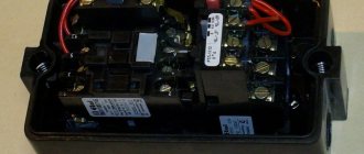
The generator is equipped with a terminal box through which it is connected to the electrical network. The protection class corresponds to GOST 14254 and has a degree of IP 65 (dust-proof design with protection from jets of water).
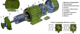
The design of this generator is shown in the figure below:
where: 1-body, 2-bottom cover, 3-top cover, 4-rotor, 5-neodymium magnets, 6-stator, 7-winding, 8-coupling half, 9-seals, 10,11,12-bearings, 13 - terminal box.
Features of generators for low-speed devices
The generators used for low-speed windmill samples are either ready-made devices with increased sensitivity and performance, or independently created axial structures with powerful neodymium magnets. Magneto modifications capable of producing high voltages with small impacts are widely used.
For efficient operation, a sufficiently large diameter of the axial generator is needed. It can achieve high linear speed of neodymium magnets at low speed. The possibilities for experimenting with sizes are almost unlimited, but it should be borne in mind that as the wind speed increases, such a generator will produce a voltage that far exceeds the capabilities of the associated equipment. In particular, rechargeable batteries cannot withstand sudden voltage surges when charging and can boil over.
Advantages and disadvantages
The advantages of wind generators made using neodymium magnets include the following characteristics:
- High efficiency of devices, achieved by minimizing friction losses;
- Long service life;
- No noise or vibration during operation;
- Reduced costs for installation and installation of equipment;
- Autonomy of operation, allowing operation without constant maintenance of the installation;
- Possibility of self-production.
The disadvantages of such devices include:
- Relatively high cost;
- Fragility. Under strong external influence (impact), a neodymium magnet can lose its properties;
- Low corrosion resistance, requiring special coating of neodymium magnets;
- Dependence on operating temperature – when exposed to high temperatures, neodymium magnets lose their properties.
Meteorological situation in the regions of Russia
Most regions of Russia are geographically located in the interior of the continent. Features of the location on the ground determine the meteorological situation, which indicates the predominance of weak and moderate winds. This situation is not able to promote the development of wind energy, at least on an industrial scale.
For the same reason, as well as because of the abundance of other, more attractive opportunities, at one time preference was given to hydropower, which became a traditional type of energy generation for Russia.
The relevance of the use of wind generators for our country is small and is concentrated mainly in the southern and steppe regions, in remote areas of the country. On an industrial scale, generating energy in this way is ineffective, since the power of a wind power plant cannot yet compete with the smallest hydroelectric power station. In addition, the wind, although a free, inexhaustible source of energy, is too unstable and can simply disappear for a while.
This situation is not suitable for energy on a national scale, so the development of wind energy in Russia will follow a different scenario.
The most pressing problem for the country is the general deterioration of electrical networks and the lack of connectivity, which is observed not only in remote, but also in many central regions of Russia.
Therefore, the main direction, which appeared spontaneously and is growing steadily, is the use of wind generators to provide energy to small areas or groups of consumers - individual houses, small farms, groups of consumers on the scale of several households.
The main problem that arose was the insolvency of the population , which limits the purchase of ready-made factory-produced units. Balance is achieved through the widespread independent production of wind generators, capable of performing their functions at a fairly high level, but costing their owners immeasurably less.
Phases - which is better - three or one?
Many lovers of electrical equipment follow the path of least resistance and, in order not to bother, opt for a single-phase stator for a windmill. However, it has one unpleasant feature that neutralizes the ease of assembly - vibration when loaded, due to the variability of current output. After all, the amplitude of such a stator is abrupt, reaching a maximum when neodymium magnets are located above the coils, and then dropping to a minimum.
But when the generator is made using a three-phase system, there are no vibrations, and the power indicator of the windmill has a constant value. The reason for this difference is that the current, falling in one phase, at the same time increases in the other. As a result, a wind generator operating in a three-phase system can be up to 50% more efficient than the exact same one using a single-phase system. And most importantly, a loaded three-phase generator does not produce vibration, therefore, the mast does not give rise to complaints about the wind generator to the supervisory authorities from ill-wishers among neighbors, since it does not create an annoying hum.
Features of the rotor and stator
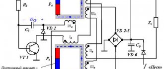
Transistor generator
To make an effective generator using neodymium alloy magnets with your own hands, consider the following recommendations when assembling:
- To increase strength, the disc is made of steel. Its thickness is made no less than that of the magnets themselves. Otherwise, part of the force field will dissipate. If the proportions are observed correctly, the sewing needle will not be attracted to the reverse side of the assembled product;
- The distance between individual magnets is made equal to or more than half the width of the products;
- The thickness of the assembled stator is made equal to or less than the thickness of neodymium magnets;
- A three-phase magnetic generator is made in proportions of 3 to 3 or 4 to 3 (the number of magnets/induction coils, respectively).
For your information. The magnets are attached, strictly observing the alternation of poles. To avoid mistakes, marks are made in advance with a marker on the corresponding edges.
Rotor creation process
The author of the development decided to make the basis of the generator a car hub with brake discs, since it is powerful, reliable and perfectly balanced.
When you start making a windmill with your own hands, you should first prepare the base for the rotor - the hub - and clean it of dirt, paint and grease. Then start gluing the permanent magnets. To create this wind generator, twenty of them were used on a disk. The size of the neodymium magnets was 25x8 millimeters. However, both their number and their size can vary depending on the goals and objectives of the person creating the wind generator with his own hands. However, to obtain one phase it will always be correct to equalize the number of poles to the number of neodymium magnets, and for three phases to maintain the ratio of poles and coils - two to three or three to four. The magnets should be positioned taking into account the alternation of poles, and as accurately as possible, but before you start sticking them, you need to either create a paper template or draw lines dividing the disk into sectors. To avoid mixing up the poles, we make marks on the magnets. The main thing is to fulfill the following requirement: those magnets that stand opposite each other must be turned with different poles, that is, attract each other.
The magnets are glued to the disks using super glue and filled in. You also need to make borders along the edges of the disks and in their center, either by wrapping tape or molding them from plasticine to prevent spreading.
Modification of a car generator
Creating a permanent magnet rotor requires quite a serious intervention in the design. It is necessary to reduce the diameter by the thickness of the magnets plus the thickness of the steel sleeve, which is placed on the rotor to form a continuous magnetic flux and at the same time serves as a landing pad for the magnets. Some experts do without a sleeve, installing magnets directly on the rotor with a reduced diameter and fixing them with epoxy.
The manufacturing process requires the participation of production equipment. The rotor is clamped into the lathe and the layer is carefully removed so that the installed magnets rotate with minimal clearance, but quite freely. The magnets are installed on the rotor plates with alternating polarity.
The greatest effect can be achieved when installing relatively small-sized magnets arranged in rows in the longitudinal direction. A smooth and powerful magnetic flux is achieved, acting on the stator power windings with uniform density at all points.
Making a rotor from a hub and brake disc
The considered method applies to ready-made generators that require minor design changes. Such devices include car generators, which are often used by amateur designers as a basic device. Often, generators are assembled completely independently, without having a ready-made device.
In such cases, they act somewhat differently. The basis is a car hub with a brake disc. It is well-balanced, durable and adapted to certain types of loads. In addition, the size of the hub allows a large number of magnets to be placed around the circumference, allowing three-phase voltage to be obtained.
Magnets with alternating polarity are placed at a distance equidistant from the center. Obviously, the highest number can be set by gluing them as close to the outer edge as possible. The most accurate indicator will be the size of the magnets, which will determine the possibility of placement at a certain distance. The number of magnets must be even so that the rhythm of alternating poles during rotation does not break down.
Gluing magnets to the hub is done using any glue; the best option is epoxy resin, which is used to completely fill the magnets. This protects them from moisture or mechanical stress. Before pouring, it is recommended to make a plasticine rim along the edge of the hub to prevent the epoxy from flowing down from the hub.
The design of the generator on a car hub is most convenient when making a vertical windmill. It is noteworthy that a similar scheme can be used without a hub, on a disk cut from ordinary plywood. This design is much lighter, allows you to choose a convenient size, which makes it possible to create a sensitive and productive device.
What is a low-speed wind turbine?
Most variants of low-speed windmills are modified examples of basic types of impellers. Horizontal types are used, which have greater efficiency, but require lifting to a sufficiently high height.
For those who do not have the opportunity to use high masts, the best option is to use vertical rotor structures. They are not capable of rotating at high speeds, which is exactly what is required in the current situation. At the same time, the capabilities demonstrated by vertical structures confirm the reality of rotation at wind speeds of 2 or even 1.4 m/s.
Rotary vertical samples are not demanding on the choice of position relative to the flow, and therefore can be effectively used at a relatively short distance from the earth's surface. The resulting turbulence, which reduces the performance of horizontal devices, is not dangerous for vertical structures and is perceived by them as ordinary wind flows. The simplicity and reliability of vertical structures have gained well-deserved popularity among amateur designers.
Windmill with axial generator on neodymium magnets
The strongest magnets with optimal parameters for use in generator design are neodymium magnets . They are somewhat more expensive than conventional ones, but they are many times superior and make it possible to create a powerful device in a relatively compact size.
There is no fundamental difference in the design. Neodymium magnets are manufactured in various form factors, allowing you to choose the most convenient option for yourself - thin oblong bars, tablet shape, cylinders, etc. if a metal rotor is used, then it is not necessary to glue the magnets; they themselves are attached to the base with force. All that remains is to fill them with epoxy to protect them from corrosion.
Strong growth in wind power
Wind energy is actively developing.
New, productive and powerful installations are appearing, capable of generating greater amounts of energy than before. The development of new models of small wind turbines is no less intensive, making it possible to supply individual households, estates, and small farms. Such confident growth of wind energy is demonstrated in foreign countries - in China, the USA, and European countries. Russia in this regard lags significantly behind its neighboring countries. Let's consider the reasons for this lag and options for overcoming them.
Winding method for windmill stator coil
In order for a do-it-yourself wind generator on neodymium magnets to work with maximum efficiency, the stator coils should be calculated.
However, most craftsmen prefer to do them by eye. For example, a low-speed generator capable of charging a 12 V battery starting from 100 - 150 rpm should have from 1000 to 1200 turns in all coils, equally divided between all coils. An increase in the number of poles leads to an increase in the frequency of the current in the coils, due to which the generator, even at low speeds, produces more power. The coils should be wound with thicker wires if possible in order to reduce the resistance in them. This can be done on a mandrel or on a homemade machine.
In order to figure out what power potential the generator has, spin it with one coil, since, depending on how many neodymium magnets are installed and what their thickness is, this indicator may differ significantly. The measurements are carried out without load at the required number of revolutions. For example, if a generator at 200 rpm provides a voltage of 30 V, having a resistance of 3 ohms, then subtract 12 V (battery supply voltage) from 30 V and the resulting result is 18 divided by 3 (resistance in ohms) we get 6 ( current in amperes), which will go from the wind generator to charge the battery. However, as practice shows, due to losses in the wires and diode bridge, the actual indicator that the magnetic axial generator will produce will be less.
It is better to take magnets for creating a wind generator in the shape of a rectangle, since their field extends along the length, unlike round ones, the field of which is concentrated in the center. Coils are usually wound round, although it is better to make them somewhat elongated, which provides a larger volume of copper in the sector, as well as straighter turns. The hole inside the coils must be equal to or greater than the width of the magnets.
The thickness of the stator should be the same as the magnets. The form for it is usually plywood; for strength, fiberglass is placed under the coils and on top of them, and the whole thing is filled with epoxy resin. In order to prevent the resin from sticking to the mold, the latter is lubricated with any fat or adhesive tape is used. The wires are first brought out and fastened together, the ends of each phase are then connected with a triangle or an asterisk.
Electrical and technical parameters of the generator
The voltage is calculated using the formula:
Homemade generator
U=2*Ch*KP*KK*KV*MI*P, where:
- U – voltage in Volts;
- H – frequency of rotation of the generator rotor per second;
- KP – number of magnetic poles;
- КК – number of induction coils in the stator;
- KV – the number of turns of the conductor in one induction coil;
- MI is the magnetic induction in T, which is formed in a standard gap (2 mm);
- P – surface area of one neodymium magnet, in sq. m.
If simple coils are used, a magnetic induction of 0.5 Tesla is taken for calculation. When adding an electrical steel core, the value is increased to 0.7-0.9 T.
For your information. The formula is valid when connecting the windings in a triangle. If a three-phase generator is assembled using a star circuit, the resulting value is multiplied by a correction factor of 1.7.
After calculating the voltage, you need to find out the resistance in the windings. After this, it will be easy to determine the current and power. For a copper conductor, the resistivity is 0.0175 Ohm per mm2/meter. To calculate the total value, use the formula:
C= (US*D)/PP, where:
- C – resistance, in Ohm;
- US – resistivity of a certain material;
- D – conductor length in meters;
- PP – conductor cross-sectional area, mm sq.
To calculate the current, subtract the voltage of the battery connected for charging from the voltage of the magnetic generator at idle. The resulting value is divided by the resistance value calculated using the previous formula.
Increasing/decreasing the speed changes the current accordingly while keeping the voltage at the battery terminals constant. To calculate the performance of a wind turbine in different modes, use the standard formula:
P=I*U, where:
- P – power, Watt;
- I – current strength, Ampere;
- U – voltage, Volt.
How to agree on the parameters of functional parts
The energy potential of the blades must correspond to a specific asynchronous motor or a self-assembled rotor with magnets. In case of significant deviations, in order to obtain sufficient electrical power, it will be necessary to create new products with the required parameters. The reverse situation is also unacceptable. Too large blades are not able to rotate quickly. Strong winds increase the risk of destruction of such structures.
To avoid mistakes, make a table with equipment operating modes at different rotation speeds in increments of 50-100 rpm. Next, they use specialized calculators that, based on the given values, calculate the geometric parameters of the screw. These products are created from suitable wood, metal, and plastic. Standard polyvinyl chloride pipes for external sewer networks are suitable as blanks.