Everyone had to observe spark discharges, including people who were far from knowledge of electrical engineering. Thunderstorms are accompanied by giant spark discharges. The release of enormous energy concentrated in the electrical discharge of lightning (see Fig. 1) is accompanied by a blinding flash of a hot barrel. One of the types of spark discharges created by humanity is an arc discharge, or simply, an electric arc.
Rice. 1. Lightning discharge
To date, the reasons for the occurrence and properties of an electric arc have been studied in detail by science. Physicists have found that in the area of its combustion there is a huge concentration of charges that form the plasma of the barrel. The temperature of the column reaches several thousand degrees.
Causes and places of occurrence
Electrical arcing is one of the deadliest and least understood electrical hazards and is prevalent in most industries.
It is widely accepted that the higher the electrical system voltage, the greater the risk to people working on or near live wires and equipment. The thermal energy from an arc flash, however, can actually be greater and occur more frequently at lower voltages with the same destructive consequences.
An electric arc usually occurs when there is accidental contact between a live conductor, such as a trolleybus or tram line contact wire with another conductor, or a grounded surface.
When this happens, the resulting short circuit current melts the wires, ionizes the air and creates a fiery channel of conducting plasma with a characteristic arc-shaped shape (hence the name), and the temperature of the electric arc at its core can reach over 20,000 ° C.
Harm and the fight against it
We have looked at the causes of an electric arc, now let's figure out what harm it causes and how to extinguish it. An electric arc causes damage to switching equipment. Have you noticed that if you plug in a powerful electrical appliance and after some time unplug the plug from the socket, a small flash occurs. This is an arc formed between the contacts of a plug and socket as a result of a break in the electrical circuit.
Important! When an electric arc burns, a lot of heat is released; its combustion temperature reaches values of more than 3000 degrees Celsius. In high-voltage circuits, the arc length reaches a meter or more
There is a danger of both harm to human health and the condition of equipment.
The same thing happens in light switches and other switching equipment, including:
- circuit breakers;
- magnetic starters;
- contactors and so on.
In devices that are used in 0.4 kV networks, including the usual 220 V, special protective equipment is used - arc chutes. They are needed to reduce the harm caused to contacts.
In general, the arc chute is a set of conductive partitions of a special configuration and shape, fastened with walls made of dielectric material.
When the contacts are opened, the resulting plasma bends towards the arc extinguishing chamber, where it is separated into small sections. As a result, it cools and extinguishes.
Oil, vacuum, and gas circuit breakers are used in high-voltage networks. In an oil switch, extinguishing occurs by switching contacts in an oil bath. When an electric arc burns in oil, it decomposes into hydrogen and gases. A gas bubble forms around the contacts, which tends to escape from the chamber at high speed and the arc cools, since hydrogen has good thermal conductivity.
In vacuum circuit breakers, gases are not ionized and there are no conditions for arcing. There are also switches filled with high pressure gas. When an electric arc is formed, the temperature in them does not increase, the pressure increases, and because of this, the ionization of gases decreases or deionization occurs. SF6 switches are considered a promising direction.
Switching at zero AC current is also possible.
Electric arc origin story
In 1801, the British chemist and inventor Sir Humphry Davy demonstrated the electric arc to his comrades at the Royal Society of London and proposed a name - electric arc. These electrical arcs look like jagged lightning strikes. This demonstration was followed by further research into the electric arc, shown by Russian scientist Vasily Petrov in 1802. Further advances in early electric arc research led to industry-leading inventions such as arc welding.
Compared to a spark, which is only instantaneous, an arc is a continuous electrical current that generates so much heat from the charge-carrying ions or electrons that it can vaporize or melt anything within the range of the arc. The arc can be maintained in DC or AC electrical circuits and must include some resistance so that the increased current does not go unchecked and completely destroy the actual source of the circuit with its consumption of heat and energy.
Arc formation, its structure and properties
Let's imagine that we are conducting an experiment in the laboratory. We have two conductors, for example, metal nails. Let's place them with their tips facing each other at a short distance and connect the leads of the adjustable voltage source to the nails. If we gradually increase the voltage of the power source, then at a certain value we will see sparks, after which a stable glow similar to lightning will form.
In this way you can observe the process of its formation. The glow that forms between the electrodes is plasma. In fact, this is an electric arc or the flow of electric current through a gaseous medium between the electrodes. In the figure below you see its structure and current-voltage characteristics:
And here are the approximate temperatures:
Physical phenomena
Electric Energy. unusual ways to get it
An electric arc between two electrodes in air at atmospheric pressure is formed as follows:
When the voltage between two electrodes increases to a certain level, an electrical breakdown occurs in the air between the electrodes. The electrical breakdown voltage depends on the distance between the electrodes and other factors. The ionization potential of the first electron of metal atoms is approximately 4.5 - 5 V, and the arcing voltage is twice as high (9 - 10 V). It is necessary to expend energy to release an electron from the metal atom of one electrode and to ionize the atom of the second electrode. The process leads to the formation of plasma between the electrodes and the burning of an arc (for comparison: the minimum voltage for the formation of a spark discharge is slightly higher than the electron output potential - up to 6 V).
To initiate breakdown at the existing voltage, the electrodes are brought closer to each other. During a breakdown, a spark discharge usually occurs between the electrodes, pulse-closing the electrical circuit. Electrons in spark discharges ionize molecules in the air gap between the electrodes. With sufficient power of the voltage source in the air gap, a sufficient amount of plasma is formed for a significant drop in the breakdown voltage or resistance of the air gap. In this case, spark discharges turn into an arc discharge - a plasma cord between the electrodes, which is a plasma tunnel. The resulting arc is, in fact, a conductor and closes the electrical circuit between the electrodes. As a result, the average current increases even more, heating the arc to 5000-50000 K. In this case, it is considered that the ignition of the arc is completed. After ignition, stable arc combustion is ensured by thermionic emission from the cathode, heated by current and ion bombardment.
After ignition, the arc can remain stable when the electrical contacts are separated to a certain distance.
The interaction of electrodes with arc plasma leads to their heating, partial melting, evaporation, oxidation and other types of corrosion.
When operating high-voltage electrical installations, in which the appearance of an electric arc is inevitable when switching an electrical circuit, combating it is carried out using electromagnetic coils combined with arc extinguishing chambers. Among other methods, the use of vacuum, air, SF6 and oil circuit breakers is known, as well as methods of diverting current to a temporary load that independently breaks the electrical circuit.
Arc structure
The structure of the electric arc in arc welding. 1-anode region, 2-arc and shielding gas region, 3-arc, 4-cathode spots, 5-cathode region
The electric arc consists of cathode and anode regions, arc column, and transition regions. The thickness of the anode region is 0.001 mm, the cathode region is about 0.0001 mm.
The temperature in the anodic region when welding with a consumable electrode is about 2500 ... 4000 ° C, the temperature in the arc column is from 7,000 to 18,000 ° C, in the cathode region - 9,000 - 12,000 ° C.
The arc column is electrically neutral. In any of its sections there are the same number of charged particles of opposite signs. The voltage drop in the arc column is proportional to its length.
Welding arcs are classified according to:
- Electrode materials - with consumable and non-consumable electrode;
- Degrees of column compression - free and compressed arc;
- According to the current used - DC arc and AC arc;
- According to the polarity of direct electric current - direct polarity (“-” on the electrode, “+” on the product) and reverse polarity;
- When using alternating current - single-phase and three-phase arcs.
Arc self-regulation
When an external disturbance occurs - a change in the network voltage, wire feed speed, etc. - a disturbance occurs in the established equilibrium between the feed speed and the melting rate. As the length of the arc in the circuit increases, the welding current and the melting speed of the electrode wire decrease, and the feed speed, while remaining constant, becomes greater than the melting speed, which leads to the restoration of the arc length. As the arc length decreases, the wire melting speed becomes greater than the feed speed, this leads to the restoration of the normal arc length.
The efficiency of the arc self-regulation process is significantly influenced by the shape of the current-voltage characteristic of the power source. The high speed of arc length fluctuations is processed automatically with rigid I-V characteristics of the circuit.
What is a welding arc
The electric arc generated by a welding machine is nothing more than a conductor consisting of ionized particles. It exists in a certain time period due to the fact that it is supported by an electric field. Such a discharge is formed in a gaseous environment capable of ionization and is characterized by a continuous form and high temperature.
In welding textbooks, this phenomenon is defined as a long-term electrical discharge in a plasma. Plasma is a mixture of protective, ionized atmospheric gases combined with fumes from metals that are formed under the influence of high temperature.
Varieties
There are several classifications of the element in question, which have different current supply schemes and the environment where it appears.
Welding
- With direct action. In this case, the equipment is installed parallel to the metal product that needs to be welded. The arc, in turn, becomes at right angles towards the electrodes and the metal surface.
- With indirect action. Appears when using two electrodes that are located at an angle of 50 degrees from the work being welded. An arc appears between the electrode and the material being welded.
The appearance of a welding arc.
In addition, it can be divided according to the principle of the atmosphere where the welding arc appears:
- Open sphere. The arc can burn in an open space with the formation of a gas phase, which contains vapor of the metal, electrode and surfaces after processing with a welding tool.
- Closed sphere. The arc burns under flux. In the gas phase near the arc, vapor from the material, electrodes and the flux layer itself enters.
- With supply of gas mixture. The arc may contain compressed gas such as helium, carbon dioxide, hydrogen, argon and other gaseous impurities. They are necessary so that the welded surface of the product is not subject to oxidation. Thanks to their supply, the environment is restored or becomes neutral to external factors. The gas supplied for operation, steam from the product being welded and the electrodes enter the arc.
In addition to the listed classifications, we can also distinguish types by duration of action:
- classic is used for constant use;
- pulse – for one-time use.
One of the most popular parts is steel, i.e. consumable electrode. However, today most professionals prefer non-melting, from which we can conclude that the types of elements under consideration are quite different from each other.
What is an electric arc?
In fact, this is the common name for an arc discharge, well known in physics and electrical engineering - a type of independent electric discharge in a gas. What are the physical properties of an electric arc? It burns in a wide range of gas pressure, at constant or alternating (up to 1000 Hz) voltage between the electrodes in the range from several volts (welding arc) to tens of kilovolts. The maximum arc current density is observed at the cathode (102-108 A/cm2), where it is contracted into a cathode spot, very bright and small in size. It moves randomly and continuously over the entire area of the electrode. Its temperature is such that the cathode material boils in it. Therefore, ideal conditions arise for thermionic emission of electrons into the near-cathode space. A small layer is formed above it, charged positively and providing acceleration of emitted electrons to speeds at which they impact ionize atoms and molecules of the medium in the interelectrode gap.
The same spot, but somewhat larger and less mobile, forms on the anode. The temperature in it is close to the cathode spot.
If the arc current is of the order of several tens of amperes, then plasma jets or torches flow out of both electrodes at high speed, normal to their surfaces (see photo below).
At high currents (100-300 A), additional plasma jets appear, and the arc becomes similar to a bundle of plasma filaments (see photo below).
Voltaic arc: characteristics
Electrical resistance along a continuous arc creates heat, which ionizes more gas molecules (where the degree of ionization is determined by temperature), and according to this sequence, the gas gradually turns into thermal plasma, which is in thermal equilibrium, since the temperature is distributed relatively uniformly across all atoms, molecules , ions and electrons. The energy transferred by electrons is quickly dispersed with heavier particles through elastic collisions due to their high mobility and large numbers.
The current in the arc is maintained by thermionic and field emission of electrons at the cathode. The current can be concentrated into a very small hot spot on the cathode—on the order of a million amperes per square centimeter. Unlike a glow discharge, the arc has a subtle structure, since the positive column is quite bright and extends almost to the electrodes at both ends. The cathode drop and the anode drop of several volts occur within a fraction of a millimeter of each electrode. The positive column has a lower voltage gradient and may be absent in very short arcs.
Practical use
When used correctly, electric arcs can have useful purposes. In fact, each of us performs a number of daily tasks thanks to the limited use of electrical arcs.
Electric arcs are used in:
- camera flashes
- spotlights for stage lighting
- fluorescent lighting
- arc welding
- arc furnaces (for the production of steel and substances such as calcium carbide)
- plasma cutters (in which compressed air is combined with a powerful arc and converted into plasma, which has the ability to instantly cut steel).
Destructive potential
An electric arc has a nonlinear relationship between current and voltage. Once the arc has been created (either by progression from the glow discharge or by momentarily touching the electrodes and then separating them), the increase in current results in a lower voltage between the arc terminals. This negative resistance effect requires that some positive form of impedance (like electrical ballast) be placed in the circuit to maintain a stable arc. This property is why uncontrolled electrical arcs in a device become so destructive, because once the arc occurs, it will draw more and more current from the DC voltage source until the device is destroyed.
The occurrence of an electric arc
The process of formation of a voltaic arc is presented in the following form. At the moment the electrodes come into contact, the passing current releases a large amount of heat at the junction, since there is a large electrical resistance here (Joule’s law).
Thanks to this, the ends of the conductors heat up to a light glow, and after disconnecting the electrodes, the cathode begins to emit electrons, which, flying through the air gap between the electrodes, split the air molecules into positively and negatively charged particles (cations and anions).
As a result, the air becomes electrically conductive.
In welding technology, the greatest application is the discharge between metal electrodes, one electrode being a metal rod, which at the same time serves as a filler material, and the second electrode being the part being welded itself.
The process remains the same as in the case of carbon electrodes, but here a new factor appears. If in a carbon arc the conductors gradually evaporated (burned out), then in a metal arc the electrodes melt very intensively and partially evaporate. Due to the presence of metal vapors between the electrodes, the resistance (electric) of a metal arc is lower than that of a carbon arc.
A carbon discharge burns at an average voltage of 40-60 V, while the voltage of a metal arc averages 18-22 V (with a length of 3 mm).
Nature and structure
When an arc is ignited, an electrical circuit is created. It involves two electrodes - the anode and the cathode, as well as a section of ionized gas. Flowing through a gas cloud, an electric current causes it to heat up and produce an intense glow associated with the emission of photons.
According to the sections of the circuit, the structure of the welding arc includes three main areas:
- anode - 10-4 cm thick;
- cathode 10-5 cm;
- arc column, 4-6 mm long.
In the first two zones, active spots appear; the maximum voltage drop and maximum heating occur in them.
The voltage drop in the welding column itself is small.
When exposed to an electric arc, in addition to elevated temperature, there is another important factor - very intense ultraviolet radiation. It has a harmful effect on the human body, primarily on the organs of vision and skin.
Welding arc structure
To avoid harm to health when working with electric welding, it is necessary to use personal protective equipment: a welding mask, gloves and thick clothing and shoes made of non-flammable materials.
Literature
- Electric arc
- article from the Great Soviet Encyclopedia. - Spark discharge
- article from the Great Soviet Encyclopedia. - Raiser Yu. P.
Physics of gas discharge. — 2nd ed. - M.: Nauka, 1992. - 536 p. — ISBN 5-02014615-3. - Rodshtein L. A. Electrical devices, L 1981
- Clerici, Matteo; Hu, Yi; Lassonde, Philippe; Milian, Carles; Couairon, Arnaud; Christodoulides, Demetrios N.; Chen, Zhigang; Razzari, Luca; Vidal, François (2015-06-01). "Laser-assisted guiding of electric discharges around objects." Science Advances 1(5):e1400111. Bibcode:2015SciA….1E0111C. doi:10.1126/sciadv.1400111. ISSN 2375—2548.
Why does it happen?
According to the theory, under normal conditions gases are dielectrics. Given the right conditions, they can be ionized, giving their elements positive or negative charges.
An external electric field with specified parameters and high temperature affect the gas, transforming it into plasma, which has all the properties of a conductor of electricity.
This property has become widespread in industry, using the arc as a gas conductor.
The algorithm for generating an electric welding arc is as follows:
- Contact . It connects the electrode and the metal.
- Breaking contact . Under the influence of current, the surface of the electrode and metal begins to melt, forming a layer of liquid metal. Over a period of time, as the melt layer increases, the contact breaks.
- Excitation of the arc . The space between the anode and cathode is filled with ions and electrons of molten metal vapors, which, under the influence of voltage, are attracted to opposite poles, exciting an arc.
- Arc stabilization . As the concentration of charged particles increases, the arc connection undergoes intense ionization; at this point, complete combustion stabilization is achieved.
- Formation of a weld pool . Under the action of the arc, the metals of the electrode and surface pass into a liquid state of aggregation, forming a mixture.
- Crystallization . After the welding power source is turned off, the surface cools to form a welded joint.
Phenomena of ionization and deionization
Internal processes that contribute to the initiation and extinction of the arc are ionization and deionization. Studying these phenomena allows us to understand the factors influencing external processes. The predominance of ionization processes is characteristic of the causes of arc occurrence. When it stabilizes, the phenomena occur with equal frequency. With the prevalence of deionization phenomena, the arc will go out.
Types of ionization:
- Thermal . The most common process that helps maintain the arc after it has formed. Due to the significant temperature effect, the number and speed of elements increases, which has a beneficial effect on ionization.
- Percussion . When moving at high speed, an electron inevitably collides with a neutral particle. After the interaction, a new charged particle is formed - an ion.
- Field electron emission . Under the influence of an external high-intensity electric field, electrons leave the surface without prior excitation.
- Edison effect or thermionic emission . When exposed to high temperature, the energy level of electrons increases. Upon reaching a certain indicator, they are able to overcome the potential barrier at the border with the metal.
Deionization phenomena include:
- Recombination . The process of interaction of particles with opposite charges is accompanied by the formation of neutrally charged elements.
- Diffusion . The process of transfer of charged particles into the environment, accompanied by the release of thermal energy.
Classification
Due to the widespread use of the welding process, the arc can be of several types. The features of the energy electric charge make it possible to distinguish the following types of it according to design and purpose:
- fusible is made of a steel alloy - during operation the metal electrode rod melts;
- infusible is relevant when working with graphite and tungsten - electrodes of this type are not consumed during welding, and the formation of the weld occurs from molten metal blanks.
According to the current supply diagram and environment
According to the electrical connection diagram, arcs for welding are divided into two types.
- Direct action. One electrode is the welding structure, and the second is the consumable element. An arc is formed at the gap.
- Indirect action. Ignition occurs between a pair of infusible parallel electrodes, after which it is brought to the workpiece to be welded.
By atmosphere
Based on the principle of atmosphere, welding arcs are of three types.
- Open sphere. In this case, arc combustion is possible in open space, and a gas sphere is formed containing metal vapor, as well as electrode and surface vapor.
- Closed. A closed arc is observed during submerged arc combustion. In the gas phase near the arc there is vapor from the material, electrode and flux layer.
- With gas mixture supply. This electric charge can contain gas in compressed form, as well as its impurities. The use of hydrogen, carbon dioxide and argon is necessary to prevent oxidation of the treated surface. Thanks to the supply of the above substances, restoration of the environment or its neutral attitude towards the factors of the latter is observed.
By duration of action
According to the duration of operation, the electric welding arc can be divided into the following types:
- constant, which is considered relevant for long-term work;
- pulsed, which is represented by a single powerful impulse; usually such an arc is used for contact welding.
What happens during an arc flash?
An arc flash begins when electricity leaves its intended path and begins to travel through the air towards a grounded area. Once this happens, it ionizes the air, which further reduces the overall resistance along the arc path. This helps attract additional electrical energy.
The arc will move in such a way as to find the closest distance to the ground. The exact distance that an arc flash can travel is called the arc flash boundary . This is determined by potential energy and many other factors such as air temperature and humidity.
When working to improve arc flash safety, the installation will often mark the arc flash boundary using floor tape. Anyone working in this area will be required to wear personal protective equipment (PPE).
Arc protection
What are the electric arc protection measures that could protect me? After analyzing the Internet, I saw that the most popular means of protecting people in electrical installations from electric arcs is a heat-resistant suit. In North America, special machines from Siemens are very popular, which protect against both electric arc and maximum current. In Russia, at the moment, such machines are used only at high-voltage substations. In my case, a dielectric glove would be enough for me, but think about how to connect lamps in them? It is very uncomfortable. I also recommend using safety glasses to protect your eyes.
In electrical installations, the fight against an electric arc is carried out using vacuum and oil switches, as well as using electromagnetic coils together with arc extinguishing chambers.
This is all? No! The most reliable way to protect yourself from an electric arc, in my opinion, is to work with voltage relief . I don’t know about you, but I won’t work under voltage anymore...
No jokes or news today. I recommend reading the article on protective equipment in electrical installations, they are all created for our protection. But no one is insured against an accident, take care of yourself.
This concludes my article on electric arc and arc protection . Do you have anything to add? Leave a comment.
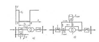
Description of the process of disconnecting the AC electrical circuit during a short circuit
When the switch contacts open, the current is not interrupted. According to Lenz's law, an emf EL=-Ldi/dt appears in the circuit, preventing a change in current. The latter finds a path for itself through the gas gap between the diverging contacts of the switch, which is blocked by an electric arc. To interrupt the current, the arc must be extinguished. In alternating current circuits, favorable conditions for arc extinction occur every time the current reaches zero, i.e. 2 times during each period. The diameter of the arc column, temperature and ionization of the gas decrease sharply. At some point in time, the current comes to zero and the arc discharge stops. However, the chain has not yet been broken.
After zero current in the gas gap, which is still somewhat ionized, the deionization process continues, i.e. the process of transforming it from a conductor into a dielectric, and in the electrical circuit the process of restoring the voltage at the switch contacts from a relatively small arc voltage to the mains voltage begins. These processes are interconnected. The outcome of the interaction of the arc gap with the electrical circuit depends on the relationship between the energy supplied to the gap and the energy losses in it, which depend on the arc extinguishing device of the switch.
If energy losses predominate throughout the entire transient process, the arc will not occur again and the circuit will be interrupted. Otherwise, the arc will arise again and the current will flow for another half of the period, after which the interaction process will repeat. The function of the switch is not so much to “extinguish” the arc, but rather to exclude the possibility of its re-ignition by effectively deionizing the gap by various artificial means. This uses the exceptional property of gas - quickly, within a few microseconds, to transform from a conductor into a dielectric capable of withstanding the restoring network voltage.
To understand the design and operation of switches, it is necessary to become familiar with the physical processes in the arc gap during the shutdown process. This article discusses arc extinguishing methods in air and oil circuit breakers.
Impact on the human body[edit | edit code]
An electric arc produces strong radiation over a wide range of waves. When burning in air, about 70% of the radiation energy comes from ultraviolet radiation, 15% from visible radiation and 15% from infrared radiation[3]. Exposure to the eyes may result in electroophthalmia and exposure to the skin may result in burns. To protect their eyes and face, welders use special welding masks with a dark filter. To protect the body, wear heat-resistant clothing.
Considering that an arc discharge is essentially an open conductor, direct exposure of a person to the arc will lead to electrical injury.
Combustion conditions
Under normal conditions, at normal pressure and temperature of 20 ° C, gases, and above all air, are not conductors. In order for them to conduct electricity, special conditions must be created: a large number of ions must be released from atomic orbits. This process is called ionization.
The work required to release one electron is called the ionization potential. For various materials it ranges from 3.5 to 20 electron volts. The lowest potential is typical for alkaline elements: potassium, calcium and their compounds. These substances are added to the electrode coating or welding wire in order to maintain stable discharge parameters. They are also added to the composition of flux powder for closed type welding.
To ensure high quality welded joints, it is necessary to maintain stable electric arc parameters, such as current, voltage, and temperature.
Temperature is determined by the following factors:
- Cathode material.
- Cathode dimensions.
- Environmental conditions.
Arc temperature distribution
The constancy of the current parameters - voltage and strength - is ensured by the current source. A large number of designs of such sources have been developed for welding work - from outdated bulky welding transformers and rectifiers to modern inverters and semi-automatic machines.
For direct and reverse polarity
DC welding can be performed in 1 of 2 ways:
- “Plus” is connected to the workpiece, i.e. it becomes the anode. This polarity is called straight.
- A minus is connected to the workpiece, so that it becomes the cathode. This is reverse polarity.
DC welding can be done in a variety of ways.
When welding with a refractory electrode, the anode spot is hotter than the cathode spot, so the first method is used to join parts of medium or large thickness. Strong heating ensures deep penetration and, as a result, high strength of the seam.
Reverse polarity connection is used to connect thin-walled workpieces. Otherwise they will burn out.
When welding with a consumable electrode, the anode spot is colder, so they do the opposite.
How is an electric arc formed?
A welding arc is nothing more than an electrical discharge. It occurs when the circuit is shorted. The moment the electrode touches the surface of the metal being welded, thermal energy begins to be generated in large quantities. At the point of contact, the metal begins to melt. The melt is attracted to the end of the consumable, forming a thin neck. It is almost instantly atomized under the influence of a strong electric field. At this time, the gas molecules are ionized, a protective cloud is formed and the free movement of the electrodes is ensured.
The type of current determines the direction of the flow. You can ignite an arc using current of direct and reverse polarity, alternating or direct. The frequency with which the arc goes out and ignites directly depends on the current parameters selected by the welder.
When welding
An extended arc can be initiated by two electrodes initially in contact and separated during the experiment. This action can initiate an arc without a high voltage glow discharge. This is the way in which a welder begins welding a joint by instantly touching the welding electrode to the object.
Another example is the separation of electrical contacts on switches, relays or circuit breakers. High energy circuits may require arc suppression to prevent contact damage.
Extinguishing methods
It should be noted that arc extinction occurs for various reasons. For example, as a result of cooling of the column, a voltage drop, or when the air between the electrodes is displaced by external vapors that prevent ionization.
In order to prevent the formation of arcs on high-voltage power line wires, they are spaced over a long distance, which eliminates the possibility of breakdown. If a breakdown between the wires does occur, the long barrel will quickly cool and extinguishment will occur.
To cool the barrel, it is sometimes divided into several components. This principle is often used in the designs of air circuit breakers designed for voltages up to 1 kV.
Some circuit breaker models contain multiple arc chutes to promote rapid cooling.
Rapid ionization can be achieved by evaporating certain materials surrounding the space of the moving knives. High-pressure evaporation blows away the plasma of the barrel, resulting in extinguishing.
There are other methods: placing contacts in oil, auto-blowing, using electromagnetic damping, etc.
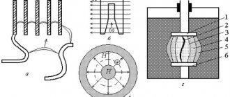
Arc extinction in oil circuit breakers
In oil switches, the contacts open in oil, but due to the high temperature of the arc formed between the contacts, the oil decomposes and the arc discharge occurs in a gaseous environment. Approximately half of this gas (by volume) is oil vapor. The rest consists of hydrogen (70%) and hydrocarbons of various compositions. These gases are flammable, but combustion in oil is impossible due to the lack of oxygen. The amount of oil decomposed by the arc is small, but the volume of gases produced is large. One gram of oil gives approximately 1500 cm3 of gas, reduced to room temperature and atmospheric pressure.
Arc extinguishing in oil switches occurs most effectively when using extinguishing chambers, which limit the arc zone, contribute to an increase in pressure in this zone and the formation of a gas blast through the arc column. Figure 9 shows a diagram of the simplest extinguishing chamber.
Fig.9. Diagram of the simplest extinguishing chamber of an oil switch
During the shutdown process, contact rod 1 moves downwards. An arc occurs between pins 1 and 2. Intense gas formation occurs and the pressure in the chamber quickly increases. The relatively cold gas formed on the surface of the oil mixes with the arc plasma. The boundary layer enters a turbulent state, promoting deionization. However, the arc cannot go out until the distance between the contacts reaches a certain minimum value determined by the recovery voltage. This minimum gap occurs when the moving contact is still in the chamber. When the rod leaves the chamber, the gases are thrown out with force. A gas blast occurs, directed along the axis, helping to extinguish the arc.
After the arc is extinguished, the contact rod continues its movement to ensure the required insulation distance in the off position.
The arc voltage of an oil circuit breaker is at least 3 times that of an air circuit breaker. The electrical strength of the gap is restored faster (at a rate of about 2 kV/µs). Therefore, with the same short-circuit current, the arc extinguishing device of the oil circuit breaker can be designed for twice the voltage and twice the characteristic impedance than the air blast device.
Discharge duration
In practical applications, continuous discharge mode is more often used. However, pulse mode is also common. It is used for contact welding.
Welding of workpieces is not carried out in a continuous seam, but at several points. Such a connection does not provide tightness, but is strong enough to make thin-walled structures, such as housings for household appliances, various devices and installations, and car bodies.
The process is carried out by a non-consumable massive electrode, which is pressed against the workpiece with great force. A short-term current of very high strength is passed through the electrode - up to several thousand amperes. At the point of contact, the metal of both workpieces melts, and at the end of the pulse it cools and crystallizes as a single whole.
Next, the electrode (or workpiece) moves along the seam line to a new point, is pressed against it and a new impulse is applied.
Roller electrodes for resistance welding
There is a variation of this method that allows you to obtain tight connections. In this case, the electrode is made in the form of a roller rolling along the surface of the workpiece. The pulses are supplied at short intervals; the guiding zones along the rolling line partially overlap and form a continuous weld material. This technology is used for automatic welding of pipelines.
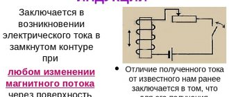
What are Foucault currents?
In a massive body, for example, a core (magnetic core) or a unit body, a volumetric current arises in the form of the movement of charged particles along circular (vortex-like) trajectories. This is called eddy currents.
A change in the magnetic flux crossing the conductor is observed in two cases:
- the conductor and the permanent magnet field move relative to each other. Example: the rotor core of an electric generator, in which the stator is a magnet (in many types the magnet is the rotor);
- There is no relative motion, but the magnetic field parameters change. To implement this option, an electromagnet (a wire wound into a coil) is used, through which alternating current is passed. Just like the current, the field will periodically change the direction of the field lines and the intensity of the magnetic flux (in antiphase with the current). Example: transformer magnetic circuit.
This phenomenon is called “Foucault currents” - in honor of the scientist J. B. L. Foucault, who did a lot of work on their study. The first to discover this phenomenon was the French scientist D. F. Arago, who in 1824 conducted an experiment with a copper disk and a magnetic needle rotating above it. The disk also began to perform similar actions. This effect began to be called in scientific circles the “Arago phenomenon.”
Magnetic field of Foucault currents
The researcher was unable to correctly explain the rotation mechanism; this was done a few years later by M. Faraday, who discovered EI:
- a flat round object is placed in a rotating magnetic field;
- its effect on the part is expressed in the induction of eddy currents in it;
- Foucault currents, in turn, interact with the magnetic field;
- the disk begins to spin.
The strength of eddy currents directly depends on the rate of change of magnetic flux.
Features of the electric arc
Thanks to its wide range of values, the electric arc is compatible with both refractory and conventional consumable electrodes. Under its influence, the metal quickly heats up, after which a melt pool is formed. The conversion of electricity into heat occurs with minimal losses.
By its nature, an electric arc is comparable to other types of charges. Its distinctive features:
- high temperature created by dense current;
- a slight decrease in cathode and anode voltage, which to a small extent depends on the initially specified voltage;
- the electric field between the poles is distributed unevenly;
- stability of the electric arc in space;
- power and current-voltage characteristics are self-regulating;
- the boundaries of the electric arc are clearly defined.
You can light the arc in one of two ways: by striking or by briefly touching it.
Further Study
In the late nineteenth century, the voltaic arc was widely used for public lighting. The tendency of electrical arcs to flicker and hiss was a serious problem. In 1895, Hertha Marx Ayrton wrote a series of articles on electricity, explaining that the voltaic arc was the result of oxygen coming into contact with the carbon rods used to create the arc.
In 1899, she was the first woman ever to read her own paper before the Institution of Electrical Engineers (IEE). Her report was entitled "The Mechanism of the Electric Arc." Shortly afterwards, Ayrton was elected as the first female member of the Institution of Electrical Engineers. The next woman was admitted to the institute in 1958. Ayrton applied to read a paper before the Royal Society, but she was not allowed to do so because of her gender, and The Mechanism of the Electric Arc was read in her place by John Perry in 1901.